Fire-Lite BG-12LX User manual
BG-12LX Addressable Pull Station
Description
The BG-12LX Addressable pull station is a non-coded,
dual-action manual pull station with a key-lock reset fea-
ture. It provides Fire•Lite intelligent control panels with
one addressable alarm initiating input. The addressable
module is housed inside the pull station. The BG-12LX
is compatible with all Fire•Lite intelligent panels. The
BG-12LX meets the ADA requirement for a 5-lb. maxi-
mum pull force to activate the pull station. Operating
instructions are molded into the pull station handle along
with Braille text. Molded Terminal numbers are also
present.
Ratings
Normal Operating Voltage: 24 VDC.
Average Operating Current (LED Flash): 300 µA.
Temperature Range: 32o F - 120o F (0o C - 49o C).
Relative Humidity Range: 10% - 93% non-condensing.
Installation
The BG-12LX Addressable pull station can be surface
mounted to an SB-10 surface backbox or semi-flush
mounted on a standard single-gang, double-gang or 4”
(10.16 cm) square electrical box. The optional BG-TR
trim ring can be used if the BG-12LX is to be semi-flush
mounted.
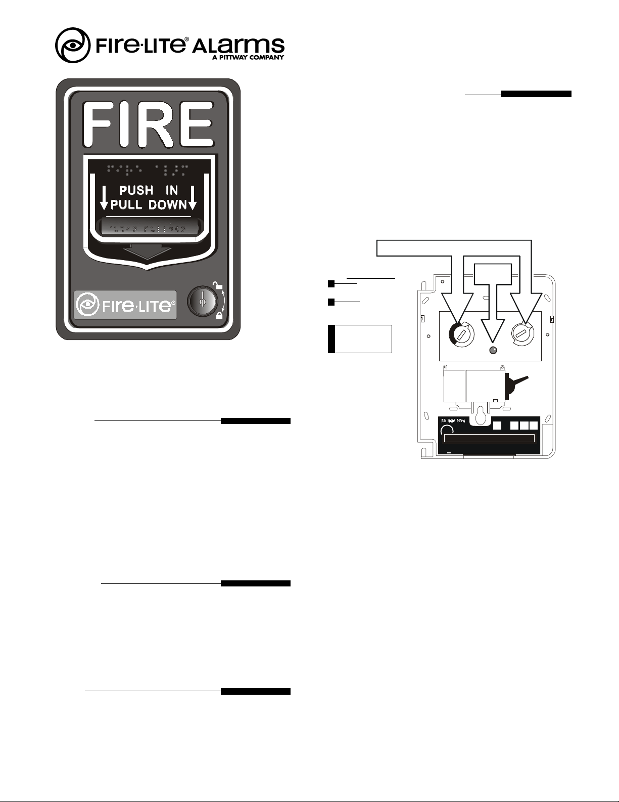
Setting the BG-12LX Address
The BG-12LX Addressable pull station is factory preset
with address ‘00.’ Set the address for the pull station by
turningtherotaryaddressswitchesontheaddressablemod-
ule mounted inside the pull station. Only one device per
address is allowed. Multiple modules may not be set to
the same address on the Signaling Line Circuit. Once the
address is set, record it in the space provided on the prod-
uct ID label located inside the pull station.
If, during mounting of the pull station, the door be-
comesdetached, complete the following steps to reattach
the door to the backplate. The door cannot be connected
to the pull station if the unit is mounted to the backbox.
1. Position the door and backplate side by side in the
full open position. (i.e. 180-degrees with respect to
each other.)
2. With the backplate position fixed, move the door be-
hind the backplate, as shown in the illustration, part
A.
3. Align the hinge posts and holes by bringing the door
up to meet the backplate, paying particular attention
to the ‘keying’ that occurs when the door’s post hole
is aligned to the backplate’s hinge post. Refer to the
illustration, part B.
4. Withthetwopiecesaligned and ‘keyed’ together, slide
the holes down onto the posts. Refer to the illustra-
tion, part C.
5. Holding the backplate, close the door and backplate
slightly to lock the door and backplate together.
Document 51094 Revision A2 ECN 00-032 01/14/2000
NORMAL
ACTIVA
TED
4 3 2 1
00
10
11
12
13
14 15 11
22
33
44
TENS ONES
66
77
88
99
55
UL A
pp
roved Label Here
LOOP
NOTIFIER
NBG - 12 Series
NON-CO DED
FIRE ALARM BOX
LISTED
23424
REFER TO DOCUMENT
Made in
U. S. A.
M
ADDRESS
L
U
PRODUCT IDENTIFICATION LABEL
ROTARY ADDRESS SWITCHES
LED
LED OPERATION
Normal:
Flash RED
Alarm:
Steady RED
Note: LED is visible
through translucent
handle.
BG12LXRotBox.cdr, label_1.cdr
bg12face.cdr

P/N 50997 REV.
REFER TO DO CUMENT
NU MB ER 5101 5 R EV.
LOOP ADDRESS
10
11
12
13
P/N 50997 REV.
REF ER T O DOCUME NT
NUMBER 51015R EV.
LOOP ADDRESS
10
11
12
13
14
9
C
B
A
POST
DOOR ‘KEYS’ INTO
BACKPLATE AT THIS POINT
POST
POST
HOLE
HOLE
1) If flush mounting, proceed to step 4.
2) Mount the backbox before wiring it to the pull station.
3) Before surface mounting the pull station, pull all wiring through the backbox and
optional trim ring.
4) Remove the appropriate amount of wire insulation. The pull station back plate is
molded with a strip gauge to measure the amount of insulation to be removed.
5) Connect the wiring from the addressable fire alarm control panel’s Signaling Line
Circuit (SLC) to Terminals 1(-) and 2(+) on the BG-12LX addressable pull sta-
tion. SLC polarity is critical for this connection.
6) Connect the wiring going to the next device on the SLC to Terminals 1 and 2,
again being certain to observe polarity.
7) Open the pull station door; align the mounting holes of the pull station backplate
to the backbox and screw into place. Tighten top and bottom screws.
8) Set the address as described in ‘Setting the BG-12LX Address’ and write the
address in the space provided on the label.
9) Insure that the alarm switch is in the normal position. Close and lock the pull
station door.
Operation
Push-in and pull-down the handle where indicated to activate the station. The BG-12LX manual fire alarm pull
station includes one SPST (Single Pole, Single Throw) N/O (normally-open) switch and the addressable mod-
ule located inside the station. Pushing-in and pulling-down the dual action handle causes the N/O alarm switch
to close. The word ‘ACTIVATED’ is displayed on the top of the handle when the pull station handle is
Pushed-in and pulled-down. The activated handle can not be reset without employing the key-lock reset. To
reset the BG-12LX pull station: 1) Insert the key and turn counterclockwise, 2) Open the door until the handle
moves back into the ‘NORMAL’ position, 3) Close the door and lock it. Closing the door automatically resets
the BG-12LX to the ‘NORMAL’ position.
CAUTION!
Install the Fire•Lite BG-12LX manual pull
station in accordance with these instructions,
applicable NFPA standards, national and local
Fire and Electrical codes and the requirements
of the AHJ (Authority Having Jurisdiction).
Regular testing of the devices should be con-
ductedinaccordancewith the appropriate NFPA
standards. Failuretofollowthesedirectionsmay
result in failure of the device to report an alarm
condition. Fire•Lite is not responsible for
devices that have been improperly installed,
tested or maintained.
For ADA compliance, if the clear floor space
only allows forward approach to an object, the
maximum forward reach height allowed is 48
in. (1,220 mm). If the clear floor space allows
parallel approach by a person in a wheelchair,
the maximum side reach height allowed is 54
in. (1,370 mm).
Note - Opening the pull station
door will not activate or
deactivate the alarm switch.
DOOR ATTACHMENT
DOOR MATED TO BACKPLATE
STRIP GAUGE
1 2 3 4
7 5 2 ) 6 """''
With the door and
backplate aligned and
‘keyed’ together, slide
the holes down onto
the posts.
Closingthedoorslightly
locks the door and
backplatetogether.
ACTIVATED
BG-12LX PULL
STATION
Document 51094 Revision A2 ECN 00-032 01/14/2000
Wiring
12LXWiring.cdr
bg12activated.cdr
12LXDoorMount.cdr
Other Fire-Lite Fire Alarm manuals

Fire-Lite
Fire-Lite BG-12SL User manual

Fire-Lite
Fire-Lite CMP-2401B User manual

Fire-Lite
Fire-Lite 411 User manual
 User manual")
Fire-Lite
Fire-Lite MS-9200(C/E) User manual

Fire-Lite
Fire-Lite LDM-32F User manual

Fire-Lite
Fire-Lite ECC-50 User manual

Fire-Lite
Fire-Lite LCD-80F User manual

Fire-Lite
Fire-Lite LCD-80FC User manual

Fire-Lite
Fire-Lite 300 Series User manual

Fire-Lite
Fire-Lite CMP-2401B User manual


Popular Fire Alarm manuals by other brands

Teknim
Teknim TFP3304 manual

Honeywell
Honeywell SILENT KNIGHT SK-5208 Installation and operation manual

Teknim
Teknim TFS-3191R Installation & operating guide

Tyco Fire Product
Tyco Fire Product TY-B Series quick start guide

Notifier
Notifier ID50 SERIES operating manual

Zircon
Zircon EN54 Installation & configuration manual


