© Inovonics, 2011 - www.inovonics.com 2
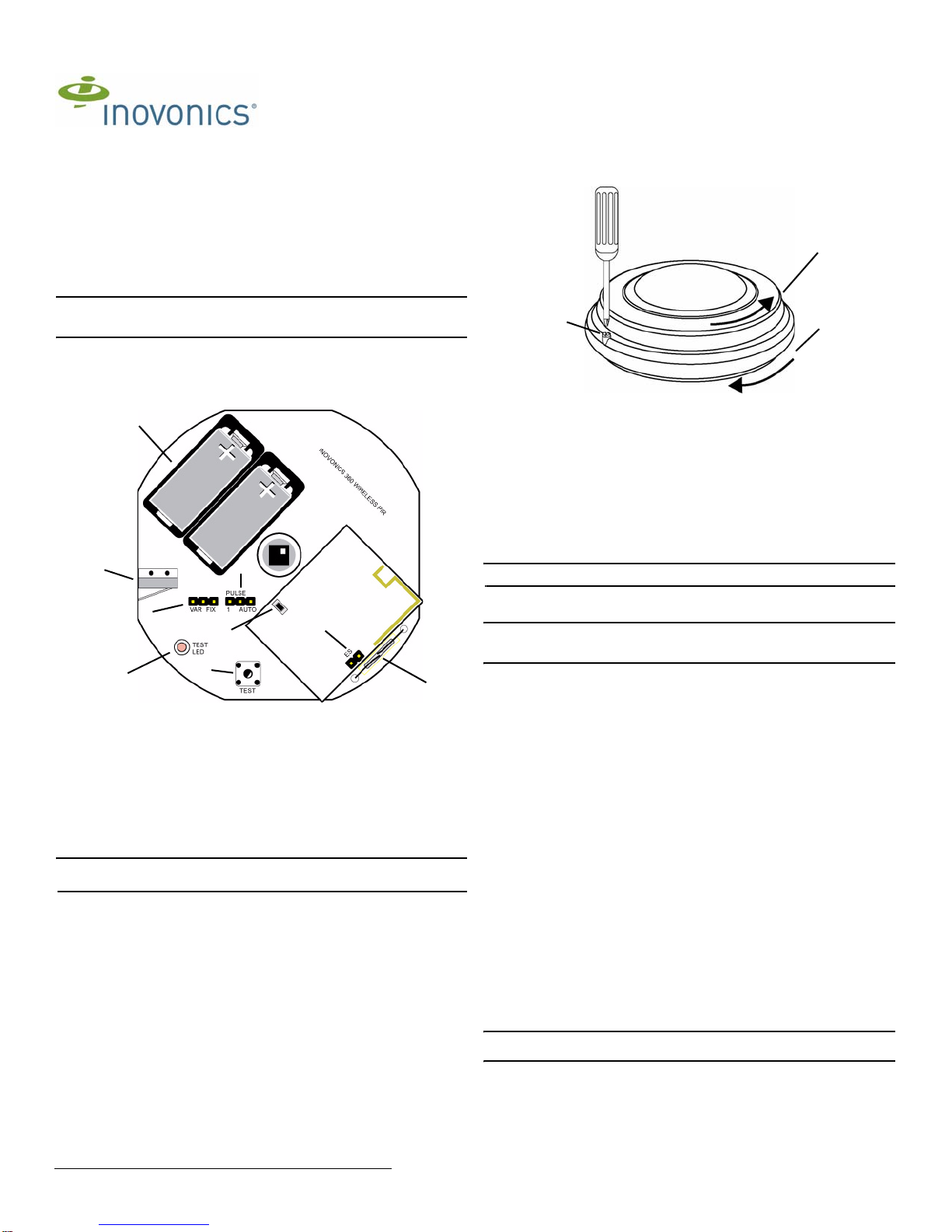
2.6 Mount the EE1265
1. Install the housing cover and housing tamper lock screw.
Note: Ensure the housing tamper lock screw is tightened sufficiently to depress the
tamper switch. If the housing tamper lock screw is not sufficiently tightened, the
EN1265 will remain in a state of tamper.
2. Remove the mounting bracket.
3. Use the provided anchors and screws to mount the EE1265 housing base to the
ceiling.
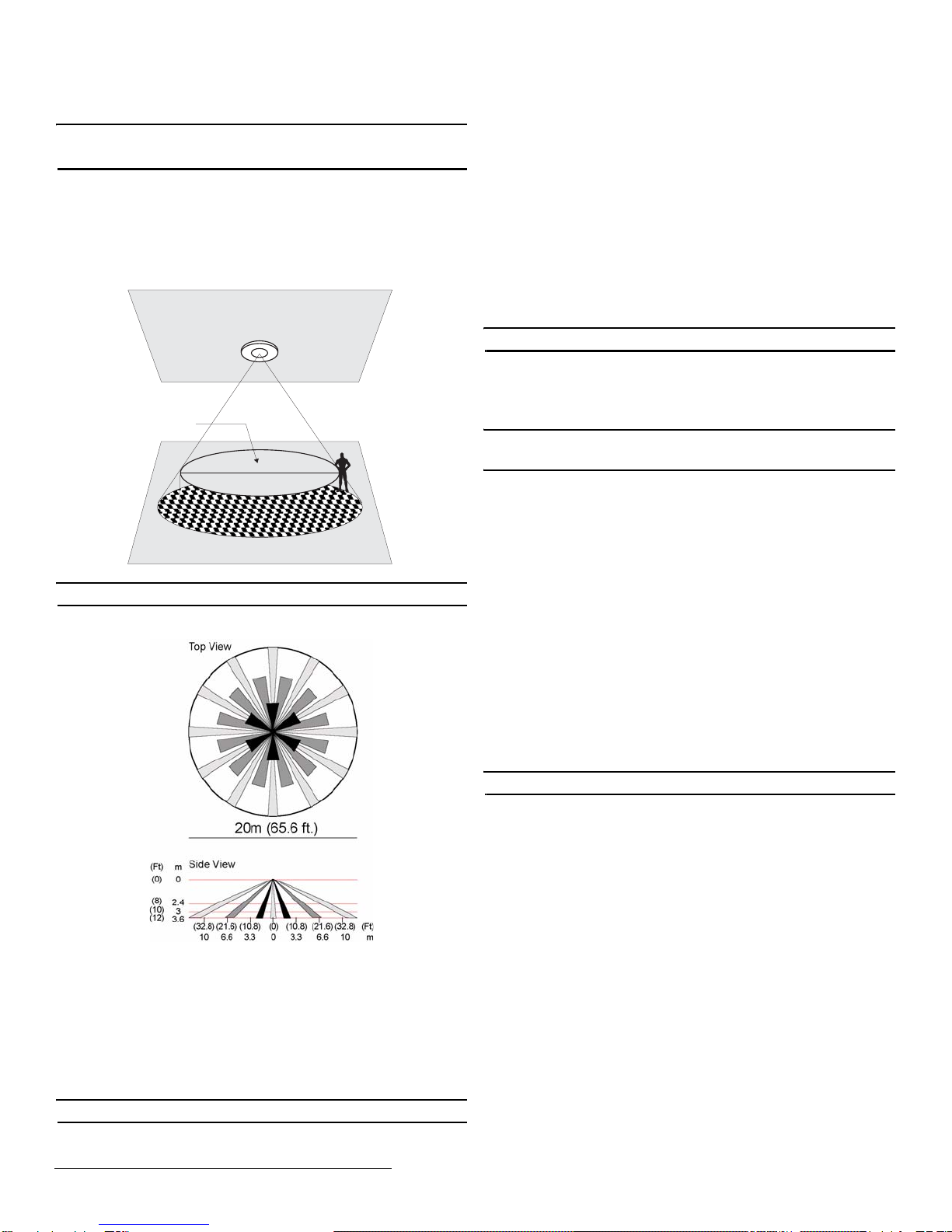
• The EE1265 can be mounted toa maximum height of approximately 12 feet (3.6
meters). As mounting height increases, distance between detection zones also
increases toward the perimeter, and the effects of factors such as floor surface
temperature and intruder direction and speed are intensified. This can contribute
to reducing the speed of detection. Every installation should include a walk test
of detection zones, including intrusion paths crossing the edges of the zones.
See Figure 3 and Figure 4 for more information.
Figure 3 EE1265 detection diameter
Note: The ACC689 long range lens allows for an install height of up to 25 feet.
Figure 4 EE1265 lens pattern
4. When the housing base has been attached to the ceiling, install the PIR on the
mounting bracket.
3 Test the EE1265
3.1 Walk Test
When in walk test mode the test LED will light every time the EE1265 senses motion.
The unit will not transmit alarm signals during this test period. There are two ways to
initiate a walk test. Once initiated, the walk test will last for one minute. To initiate a
walk test:
1. With the cover off the unit, pass a magnet near the walk test reed switch for one
second, or press the test button for one second.
Note: The test LED only lights during the walk test and the transmission test.
3.2 Transmission Test
When in transmission test mode the unit will transmit alarm and restoral cycles at
regular intervals for approximately one minute. The LED will light every time the unit
transmits. To initiate a transmission test:
1. With the cover off the unit, hold a magnet near the walk test reed switch for at
least three seconds, or press the test button for at least three seconds.
4 Operation
The EE1265 contains a tamper switch on the board to alert the user if the housing
cover is removed. The EE1265 also contains tamper contacts in the mounting bracket
to alert the user if the unit is removed from the wall.
5 Specifications
Dimensions: 131mm x 57mm (5.2" x 2.25")
Weight: 185g (6.52 oz.)
Detection method: 4-element PIR
Operating temperature: 0°C to 49°C (32°F to 120°F)
Humidity: 10% to 90% non-condensing
Battery: Inovonics BAT604 (3.0V lithium Duracell DL123A)
Note: Battery is supervised
Typical battery life: 2 years in location with low to moderate activity
Visible light protection: Stable against halogen light 8 feet (2.4m) or reflected light
Temperature compensation: Yes
Pulse count: Selectable single pulse or multiple pulse
6 Warranty/Disclaimer
Caution: Changes or modifications to this unit not expressly approved by Inovonics
Wireless Corporation may void the installer's authority to operate the equipment as
well as the product warranty.
Inovonics Wireless Corporation ("Inovonics") warrants its EchoStream products
("Product" or "Products") to conform to its own specifications and to be free of defects
in materials and workmanship under normal use for a period of thirty-six (36) months
from the date of manufacture. Within the warranty period, Inovonics will repair or
replace, at its option, all or any part of the warranted Product. Inovonics will not be
responsible for dismantling and/or reinstallation charges. To exercise the warranty, the
User ("User", "Installer" or "Consumer") must work directly through their authorized
distributor who will be given a Return Material Authorization ("RMA") number by
Inovonics. Details of shipment will be arranged directly through the authorized
distributor.
This warranty is void in cases of improper installation, misuse, failure to follow
installation and operating instructions, alteration, accident or tampering, and repair by
anyone other than Inovonics.
This warranty is exclusive and expressly in lieu of all other warranties, obligations or
liabilities, whether written, oral, express, or implied. There is no warranty by Inovonics
that Inovonics product will be merchantable or fit for any particular purpose, nor is
there any other warranty, expressed or implied, except as such is expressly set forth
herein. In no event shall Inovonics be liable for an incidental, consequential, indirect,
special, or exemplary damages, including but not limited to loss of profit, revenue, or
contract, loss of use, cost of down time, or interruption of business, nor any claim
made by distributor's customers or any other person or entity.
This warranty will not be modified or extended. Inovonics does not authorize any
person to act on its behalf to modify or extend this warranty.
This warranty will apply only to Inovonics Products. Inovonics will not be liable for any
direct, incidental, or consequential damage or loss whatsoever, caused by the
malfunction of Product due to products, accessories, or attachments of other
manufacturers, including batteries, used in conjunction with Inovonics Products.
Note: E-mail support@inovonics.com for a copy of the CE Declaration of Conformity.
Ceiling - 3 m (10 ft)
Effective Detection Diameter
14 m (46 ft)
0.8 M (2.6 Ft)
Floor