manuals.online logo
Brands
  1. Home
  2. •
  3. Brands
  4. •
  5. Bosch
  6. •
  7. Smoke Alarm
  8. •
  9. Bosch FAD-325-V2F User manual

Bosch FAD-325-V2F User manual

BOSCHSECURITYSYSTEMS,INC.
130PerintonParkway
Fairport,NY14450USA
II. MOUNTING THEDETECTOR
Thesamplingtubesmaybeorderedtoa desiredlengthororderedinoneof3 standardlengthsandcut
perrequirements. Theintakesamplingtubeconsistsofapieceof steelpipingwithaseriesofholes
drilledtheentirelengthofthetubeandshouldextendtheentirewidth oftheduct.Theholesmustbe
facingintotheairflow(seeFigure2). Theexhausttubeconsistsofapieceofsteelpiping
approximately7-1/2"long.
1.Removepaper backingfrommountingtemplateAP121(packagedin installationkit)andaffixto
ductatdesiredlocation.
2.Usingtemplateasa guide, drill4mountingholes(3/32"diameter)forductmountingscrews(4#12
x1/2"sheetmetalscrewspackagedininstallationkit). Drillorpunchholesforsamplingtubesinair
ducts(1-3/8"diameter),usingtemplateasa guide. Cleanallholes.
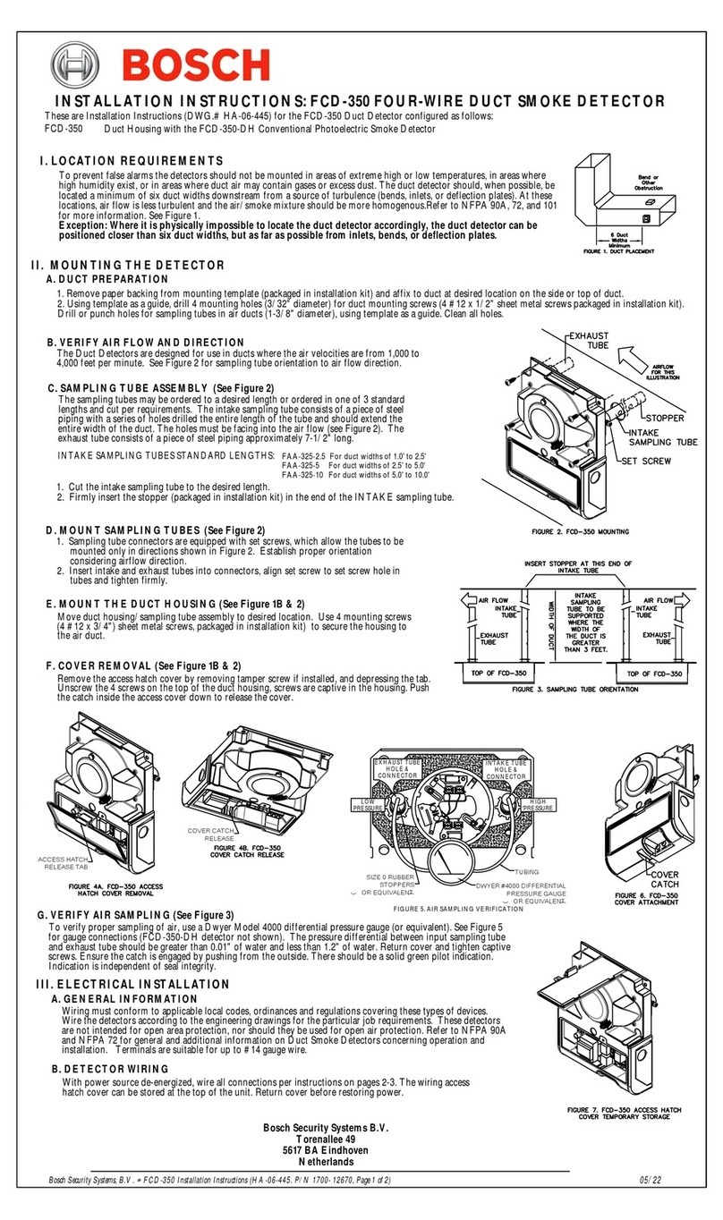
DuctSmoke Detector LocationRequirements:
detectorsshouldnotbemountedinareasofextremehighorlowtemperatures,in
areaswherehigh humidityexist,orinareaswhereductairmaycontaingasesor
excessdust.Theductdetectorshould,whenpossible,belocatedaminimumofsix
duct widthsdownstreamfroma sourceofturbulence(bends,inlets,ordeflection
plates).Attheselocations,airflowislessturbulentandthe air/smokemixture
shouldbemorehomogenous.RefertoNFPA90A,72,and101formoreinformation.
SeeFigure1Aand1B.
Exception:Where itisphysically impossible tolocatetheductdetectoraccordingly,
theductdetectorcan be positioned closer thansixductwidths,butasfaras
possiblefrominlets, bends,or deflectionplates .
*TheseproductsarecompatibleexclusivelywithfirealarmcontrolpanelsthatutilizeBOSCH'sprotocol,DCP.
TheseareInstallationInstructions(DWG.# HA-06-184) fortheAnalogDuctHousingcustomizedasfollows:
FAD-325 DuctHousingwiththeFAD-325-DHAnalogPhotoelectricSmokeSensor*
FAD-325-V2F Duct Housingwith theFAD-325-V2F-DHAnalogPhotoelectricSmokeSensor*
FAD-325-R Duct HousingwiththeFAD-325-DHAnalogPhotoelectricSmokeSensor&Relays*
FAD-325-V2F-R DuctHousingwiththe FAD-325-V2F-DHAnalogPhotoelectricSmokeSensor&Relays*
INSTALLATIONINSTRUCTIONSFORTHEDUCTSMOKEDETECTOR
A.DUCTPREPARATION
TheDuctDetectorsaredesignedforusein ductswheretheair velocitiesare from300to4000feetper
minute. Verify this bycheckingspecificationsofinstallationandifnecessary,useanAlnorModel
6000Pvelocitymeter(orequivalent)tochecktheairvelocity.SeeFigure2forsamplingtube
orientation toairflowdirection.
SET
SCREW CONNECTORS
FIGURE 1B:DUCT HOUSINGMOUNTING
TOPOF DUCTHOUSING
DUCT MOUNTING
SCREWS
FIGURE 2 SAMPLING TUBE ORIENTATION
INSERT STOPPERAT THISENDOF
INTAKETUBE
TOP OF DUCT HOUSING
EXHAUST
TUBE
AIRFLOW
INTAKE
TUBE
INTAKE
SAMPLING
TUBETOBE
SUPPORTED
WHERETHE
WIDTHOF
THEDUCTIS
GREATER
THAN 3FEET.
WIDTHOFDUCT
TOP OF DUCT HOUSING
EXHAUST
TUBE
INTAKE
TUBE
AIRFLOW
EXHAUST
TUBE
Bendor
Other
Obstruction
6Duct
Widths
Minimum
FIGURE1A
TEMPLATE
AIRFLOW
FORTHIS
ILLUSTRATION
INTAKE
SAMPLING
TUBE
STOPPER
1.Withpowersourcede-energizedandthesmokedetectornotinstalled,wire allconnectionsperengineeringdrawings.
Referto theapplicablefiguresbelowdependingonyourducthousingmodelnumber.
2.Withallwiringinplace,installthedetectorhead.
3.Energizetheductdetector.
Wiring must conformtoapplicable localcodes, ordinancesand regulations covering thesetypesofdevices. Wirethedetectorsaccordingtotheengineeringdrawingsforthe
particularjobrequirements. Thesedetectorsare notintendedforopenarea protection,norshouldtheybeusedfor openairprotection.Referto NFPA90AandNFPA72for
generalandadditionalinformationonDuctSmoke Detectorsconcerningoperationandinstallation. Terminalsaresuitableforupto#14gaugewire.
Toverifypropersamplingofair,usea DwyerModel4000 differentialpressuregauge(orequivalent).
SeeFigure3forgauge connections. Thepressuredifferentialbetweeninputsamplingtubeand
exhausttubeshouldbegreaterthan0.01"of waterandlessthan1.2"ofwater.
Moveducthousing/samplingtubeassemblytodesiredlocation. Use4 mountingscrews(4#12x1/2"sheet
metalscrews,packagedininstallationkit) tosecurethehousingtotheairduct.
1. Samplingtubeconnectorsareequippedwith setscrews,which allowthetubestobemounted
onlyindirectionsshown in Figure 2. Establish properorientationconsideringairflowdirection.
2. Insertintakeandexhausttubesintoconnectors,alignsetscrewtosetscrewholeintubesand
tightenfirmly.
1. Cuttheintakesamplingtube tothedesiredlength.
2. Firmlyinsertthestopper(packagedininstallationkit) intheendof theINTAKEsamplingtube.
INTAKESAMPLINGTUBESSTANDARDLENGTHS:
III.ELECTRICAL INSTALLATION
FIG. 3AIRSAMPLING
VERIFICATION
For duct widths of 1.0' to 2.5'
For duct widths of 2.5' to 5.0'
For duct widths of 5.0' to 10.0'
EXHAUSTTUBE
HOLE&
CONNECTOR
LOWPRESSURE
SIDE
FAA-325-2.5
FAA-325-5
FAA-325-10
DWYER#4000DIFFERENTIAL
PRESSURE GAUGE(OR
EQUIVALENT)WITH TUBING
AND SIZE0RUBBERSTOPPERS
(HA PART#0700-01118).
HIGHPRESSURE
SIDE
INTAKETUBE
HOLE&
CONNECTOR
Note: Allductdetectormodelscanbetestedwith actualsmoke. Removetheductdetector cover. Testthedetectorheadbylightingapieceofcotton
clothesline.andplacingitapproximately3 inchesfromthedetectorhead. Blowacrossthelitendoftheclothesline towardthedetector. TheLEDsonthe
detectorshouldilluminatewithinoneminute. Afterperformingthistest sequence,reinstalltheductdetectorcover.
Theseductsensors areanalogaddressableandcanbecalibratedbyaU.L.Listedanalogcontrolpanel. SeetheFACPInstallation
Instructions for specificdirections.
Models FAD-325/FAD-325-V2F/FAD-325-R andFAD-325-V2F-R
BOSCHSecuritySystems,Inc. * FAD-325Installation Instructions(HA-06-184.P/N1700-11140Page1of2) Specifications subject tochangewithoutnotice.*February2017
B. VERIFY AIR FLOW ANDDIRECTION
C. SAMPLINGTUBE ASSEMBLY (See Figure2)
D. MOUNTSAMPLING TUBES (SeeFigure2)
E.MOUNT THE DUCTHOUSING (See Figure 1B&2)
F. VERIFY AIR SAMPLING (See Figure3)
A. GENERAL INFORMATION
B. DETECTORWIRING
I.LOCATION REQUIREMENTS Toprevent falsealarmsthe
TerminateRemoteAccessories asindicatedabove(ifrequired).
This is nota self-containedstandalonedetector.
AU.L.ListedAnalogAddressable FireSystem isrequired.
ANALOGADDRESSABLE
FIELDLOOPWIRING
REMOTETEST
SWITCH
(Testfunctiononly. doesnotreset.)
REMOTE
ALARM
LED
6
III.ELECTRICALINSTALLATION,continued
OBSERVEPOLARITY
INPUTVOLTAGE
24V.D.C.
S(+)
SC(-)
ULLISTED
CONTROLPANEL
A.A.
CONTROL
PANEL
ADDRESSABLE
LOOP
1 2 +
-
REMOTE
PILOTLED
10mAStandby
55mAAlarm
3 4
+-
+5
FAD-325-R/FAD-325-V2F-R WIRINGDIAGRAM
FAD-325/FAD-325-V2FWIRINGDIAGRAM
TheFAD-325,FAD-325-V2F,FAD-325-Rand
FAD-325-V2F-Rarenotself-containedsensors.
Thisproductis compatibleonlywithfirealarm
controlpanelsthatutilizeBOSCH'sDigital
CommunicationsProtocol,DCP.
Forexamplethe FPA-1000 FamilyofControlPanels
D.WIRING DIAGRAMS,continued
ULLISTED
CONTROLPANEL
LOOP INTERFACE
S(+)
SC(-)
SUPPLYVOLTAGE
TONEXTSENSOR
ORRETURN
TOCONTROLPANEL
ALARMCONTACTS
10.0A@250VAC
NC
ALARMCONTACTS
10.0A@250VAC
NONC C
7 8 9 10
NO
C
1211
THED304REMOTEALARMLED
WIRINGMUSTHAVEPOLARITYAS
SHOWN24 VDC(8mAMAX.)
-R +RL2L1
FANSHUTDOWNEXAMPLE
421 3
(-)
FAN
TONEXT
SENSOR
(+)
FAD-325-DH/FAD-325-V2F-DH
ANALOGSENSOR
* Remotecommonalarmindication,remotepilotindication,remotecommonreset,commonshutdownandcommonvisualindication.
* Commonfaultindication(whengreenpilotLEDisextinguished)cannotbeachievedontheFAD-325DuctUnits. IndividualRemote
PilotLED'smustbeinstalledtomonitordetectorheador powersourceremovalforeachunit.
* Intheeventofanalarm,thedetectorheadandductunitalarm(Red)LED'swill beilluminated. AllremainingductunitalarmLED'swill
notbe illuminated.All remotealarmLED'sfittedto theductunitswillbe illuminatedwhenanyoftheunitsgointoalarm. Onlytheduct
unitinalarmwill permitresettingof thesystemfromthebuiltintest/resetswitchonthatparticularductunit.
* Acommon Remoteresetswitchwillresetalldetectors.
Commonfunctionsincludeoneorall ofthefollowing:
BOSCHSecuritySystems,Inc. * FAD-325 Installation Instructions (HA-06-184.P/N1700-11140Page2of2) Specifications subject tochangewithoutnotice.*February2017
TheBosch D304/D305Remote DuctAnnunciatorandtheBosch
FAD-325-R/FAD-325-V2F-RDuct Detectorsarecompatiblewhen
wiredas thefollowing.
STANDBY350µA
ALARM800µA

This manual suits for next models

3

Other Bosch Smoke Alarm manuals

Bosch D296 Series User manual

Bosch

Bosch D296 Series User manual

Bosch D263TH User manual

Bosch

Bosch D263TH User manual

Bosch FAD-425-O-R User manual

Bosch

Bosch FAD-425-O-R User manual

Bosch FERION 4000 O User manual

Bosch

Bosch FERION 4000 O User manual

Bosch FAS-420-TM User manual

Bosch

Bosch FAS-420-TM User manual

Bosch FMM‑325A Series User manual

Bosch

Bosch FMM‑325A Series User manual

Bosch FAD?420?HS?EN User manual

Bosch

Bosch FAD?420?HS?EN User manual

Bosch FPD-7024 User manual

Bosch

Bosch FPD-7024 User manual

Bosch D285 User manual

Bosch

Bosch D285 User manual

Bosch FAS-420-TM-R User manual

Bosch

Bosch FAS-420-TM-R User manual

Bosch FAP-OT 420 KKW User manual

Bosch

Bosch FAP-OT 420 KKW User manual

Bosch FAA-350-B6 User manual

Bosch

Bosch FAA-350-B6 User manual

Bosch D1255RB/D1256RB/D1257RB User manual

Bosch

Bosch D1255RB/D1256RB/D1257RB User manual

Bosch F220 User manual

Bosch

Bosch F220 User manual

Bosch FAS-420-TT Series User manual

Bosch

Bosch FAS-420-TT Series User manual

Bosch DRA 12/24 User manual

Bosch

Bosch DRA 12/24 User manual

Bosch D340 User manual

Bosch

Bosch D340 User manual

Bosch ISN-CP1-CM-W50 User manual

Bosch

Bosch ISN-CP1-CM-W50 User manual

Bosch RFSM-A User manual

Bosch

Bosch RFSM-A User manual

Bosch MAGIC.SENS series User manual

Bosch

Bosch MAGIC.SENS series User manual

Bosch D326A Application guide

Bosch

Bosch D326A Application guide

Bosch D296/D297 User guide

Bosch

Bosch D296/D297 User guide

Bosch twinguard User manual

Bosch

Bosch twinguard User manual

Bosch twinguard User manual

Bosch

Bosch twinguard User manual

Popular Smoke Alarm manuals by other brands

Rosslare SA-64-2W installation manual

Rosslare

Rosslare SA-64-2W installation manual

bolid S2000-IPDL user manual

bolid

bolid S2000-IPDL user manual

SGC STEALTH Kit quick start guide

SGC

SGC STEALTH Kit quick start guide

Gentex 913 SERIES Installation instructions - owner's information

Gentex

Gentex 913 SERIES Installation instructions - owner's information

brennenstuhl BR 5232 operating instructions

brennenstuhl

brennenstuhl BR 5232 operating instructions

MIIDEX LIGHTING MV3 instructions

MIIDEX LIGHTING

MIIDEX LIGHTING MV3 instructions

Radal Technology Cig-Arrête CSA-FDV user guide

Radal Technology

Radal Technology Cig-Arrête CSA-FDV user guide

Siemens DB-ADPT installation instructions

Siemens

Siemens DB-ADPT installation instructions

System Sensor 2151 Installation and maintenance instructions

System Sensor

System Sensor 2151 Installation and maintenance instructions

eTIGER ES-D5B user manual

eTIGER

eTIGER ES-D5B user manual

BRK electronic 2002 user manual

BRK electronic

BRK electronic 2002 user manual

Mini Gadgets BB2Smoke10 user manual

Mini Gadgets

Mini Gadgets BB2Smoke10 user manual

Abus FURM50000 Installation and operating instructions

Abus

Abus FURM50000 Installation and operating instructions

thefirebeam Xtra user guide

thefirebeam

thefirebeam Xtra user guide

Electronics Ei 605 Optical quick start guide

Electronics

Electronics Ei 605 Optical quick start guide

Electronics Ei 605C Installation

Electronics

Electronics Ei 605C Installation

Fire-Lite AFM-16ATX user manual

Fire-Lite

Fire-Lite AFM-16ATX user manual

Proflex CERAMIHEAT smoke monster  Pro S 25 user manual

Proflex

Proflex CERAMIHEAT smoke monster Pro S 25 user manual

manuals.online logo
manuals.online logoBrands
  • About & Mission
  • Contact us
  • Privacy Policy
  • Terms and Conditions

Copyright 2025 Manuals.Online. All Rights Reserved.