INST AP-330 D140113
2
LOCATION PREREQUISITES
This guideline contains general information on duct smoke detector
installation, but does not preclude the NFPA and/or ICC documents
listed. Air Products and Controls assumes no responsibility for improperly
installed duct detectors. To determine the correct installation position
for an SL-DA4R Series duct smoke detector, the following factors must
be considered.
1. A uniform non-turbulent (laminar) airow between 100 ft/min. to
4,000 ft/min. must be present in the HVAC duct.To determine duct
velocities, examine the engineering specications that dene the
expected velocities or use an Alnor model 6000AP velocity meter
(or equivalent).
2. To minimize the impact of air turbulence and stratication on
performance, a duct smoke detector should be located as far as
possible downstream from any obstruction (i.e. deector plates,
elbows, dampers, etc.). In all situations, conrmation of velocity and
pressure differential within specications is required.
The pressure differential between the input sampling (high pressure)
tube and exhaust (low pressure) tube for the SL-DA4R Series smoke
duct detector should be greater than 0.01 inches of water and less
than 1.2 inches of water.
3. Identify a code compliant location (supply or return side, or both)
for the installation of the duct unit that will permit easy access for
viewing and serviceability.
4. When installing on the return side, install duct units prior to the air
being exhausted from the building or diluted with outside“fresh” air.
5. When installing duct smoke units downstream of lters, res
occurring in the lters will be detected, but if the lters become
blocked, insufcient air ow through the duct unit will prevent the
correct operation of the duct detector. Duct units installed in the
supply air side may monitor upstream equipment and/or lters.
6. Where possible, install duct detectors upstream of air humidiers
and downstream of dehumidiers.
7. To prevent false alarms, the duct detector should not be mounted
in areas of extreme high or low temperatures, in areas where high
humidity exists, or in areas where the duct may contain gases or
excessive dust.
SAMPLING TUBE ASSEMBLY
The SL-DA4R Series duct smoke detectors employ a specially notched
sampling tube, which may be ordered separately in one of four standard
lengths or packaged as FAST Tubes.
STN-1.0 For duct widths of 6” TO 1.0’
STN-2.5 For duct widths of 1.0’ TO 3.0’
STN-5.0 For duct widths of 3.0’ TO 5.0’
STN-10.0 For duct widths of 5.0’ TO 10.0‘
FAST Tubes Sectional tubes for duct widths up to 8.0’
Standard sampling tubes are steel tubes with air intake holes drilled
the entire length of the tube. FAST Tubes are a recognized plastic with
an open slot along the length. These tubes can be cut to length and
must span at least 80% of the duct width (spanning the entire width is
suggested). Sampling tubes over 3.0’ must be supported on the opposite
side of the duct. To ensure the correct operation of the sensing tube,
the red end cap (red stopper in installation kit) must be inserted in the
end of the air intake sampling tube. For custom duct widths, always use
the next longest standard size and cut down to the exact requirement.
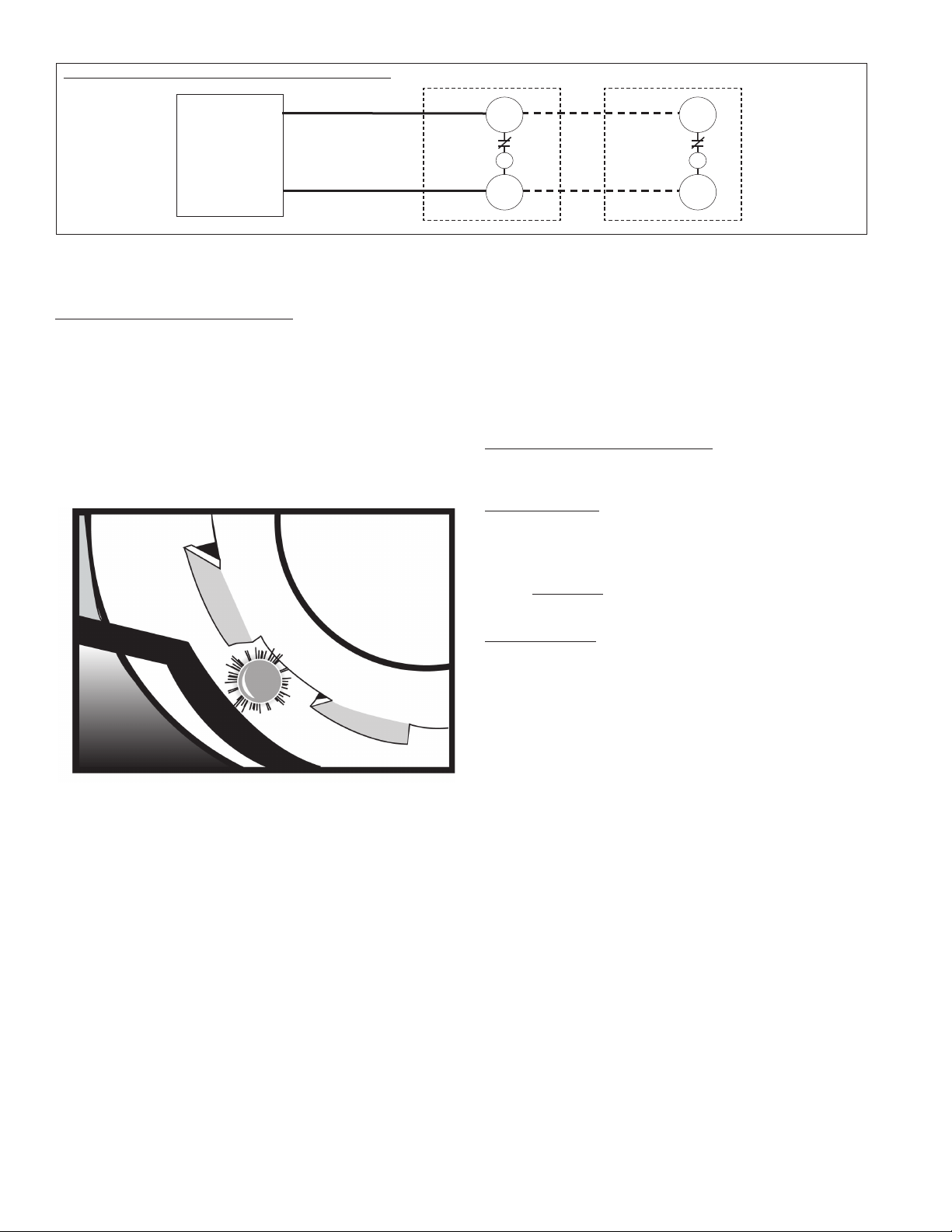
MECHANICAL INSTALLATION
“NO-TOOLS” TUBE INSTALLATION
The SL-DA4R Series duct smoke detector provides a unique, patented
mechanism for installation and/or removal of the sampling and exhaust
tubes from either the front or rear of the detector housing.
Once the airflow direction has been determined, insert the inlet and
exhaust tubes into the duct smoke detector. If the cover is in place, the
tubes may be inserted into the back of the detector via the key-slots
provided. Simply push the tube into place against the spring loaded
retainer, and turn into the correct position, allowing the key to “lock”
the tube in the desired orientation. For front side installation, simply
rotate the tube retainer until the tube may be inserted and oriented
properly. Once the tube is installed, rotate the retainer back into place
to lock down the tube. Ensure air intake sampling tube is positioned so
that the inlet holes (or Fast Tube slot) are directly facing the airflow.
INLET TUBE
HOLES FACE
AIR FLOW
DUCT WIDTH AIR FLOW DIRECTION
INSERT RED STOPPER
THIS END OF INLET TUBE
EXHAUST TUBE INSTALLED
DOWNSTREAM OF AIRFLOW
DO NOT INSERT RED STOPPER
NOTE:Mountings shown
are typical. Detectors can
be installed side, bottom
or top of duct as long as
proper tube operation and
flow/pressure performance
is maintained
Tube Support Hole only for Ducts Greater than 3 Feet Wide
MOUNTING
After securing the sampling and exhaust tubes to the duct smoke unit,
(or initially placing the tubes through the 1¼” holes drilled or punched
in the HVAC duct to accept the inlet sampling and exhaust tubes and
then attaching them to the duct unit), hold the duct unit assembly in
position and use (2) # 12 X ½” sheet metal screws (packaged in the
installation kit) to secure the duct smoke detector to the HVAC duct
sheet metal.
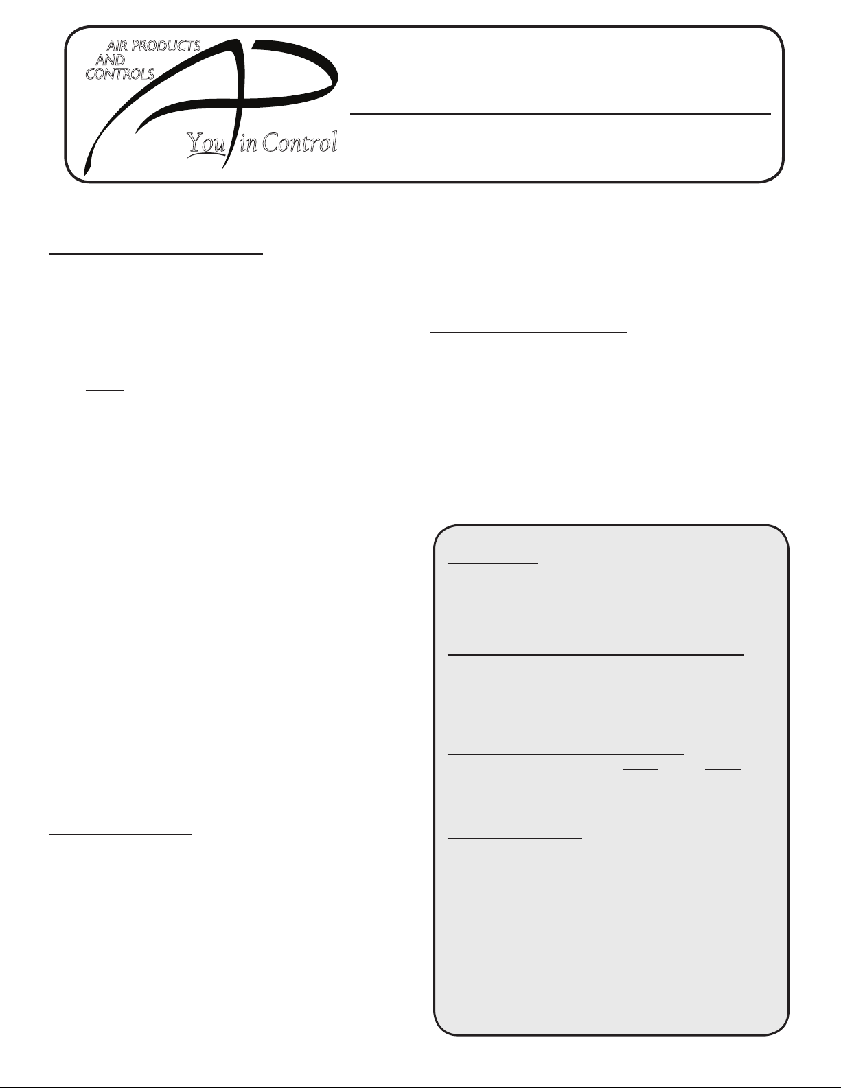
AIR SAMPLING VERIFICATION
To ensure correct operation of the duct unit use a Magnehelic
differential pressure gauge, Dwyer 2000 or 4000 Series (or equivalent)
to determine the differential pressure between the inlet (high side) and
exhaust (low side) tubes. The differential pressure between the two
tubes should be greater than 0.01 inches of water and less than 1.2
inches of water. This duct smoke detector is shipped with a velocity
adapter insert, either factory installed (SL-DA4R-P), or found in the
installation kit (SL-DA4R-N). When installed, this adapter will allow
the duct detector to operate at extremely low air velocities. To install
the adapter, simply insert it into the slots provided inside the detector
housing so that the adapter fits snugly over the smoke detector head.
For Ionization models only: Unless your system is consistently
operating in the slower velocity range (where the adapter is specifically
required), we recommend that the adapter not be inserted. If you
experience false alarms at higher velocities with the adapter in place, the
adapter should be removed.