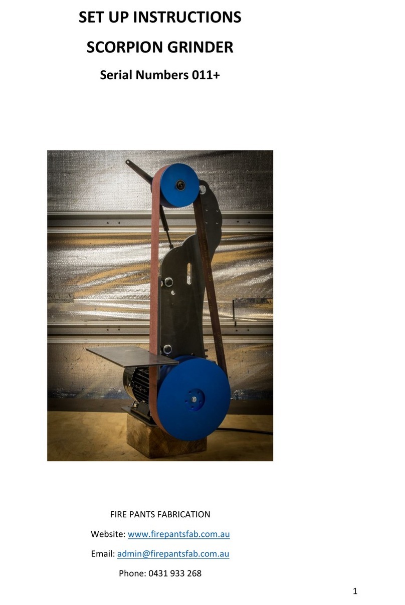
Fire Pants Fabrication FIRE ANT Manual

2
TABLE OF CONTENTS
SECTION DESCRIPTION PAGE
1 Introduction 3
2 Specifications 3
3 Unpacking 4
4 Setting Up 5

3
1. INTRODUCTION
The Fire Ant Grinder has been born out of my own needs to have a low
cost, functional, versatile, high performing grinder. The modular design
allows for quick and easy assembly.
Features include:
2" x 72" (50 x 1830mm) Belt capacity, for the biggest range of
consumables.
Solid 6mm steel construction, laser cut for accuracy.
3 x tool rest and platen slots for versatility.
Standard platen can be adjusted to a wide range of angles, with
markings every 10" for easy set up.
Quickly adjust for flat platen, to slack belt, to contact wheel.
Ceramic platen backrest option available.
6061 aluminium platen, tracking, and drive wheels for long life.
5" drive wheel (to suit 2hp motor) for optimal belt speed / torque.
Constant development of new tooling and attachments, for both
knife making and general fabrication applications.
Australian Designed and Built.
Extended length platen backrest for greater control.
NOTE: PLEASE DO NOT OPERATE THE FIRE ANT GRINDER UNTIL YOU
HAVE READ THESE INSTRUCTIONS AND ARE FAMILIAR WITH ITS
CONTROLS. THE FIRE ANT GRINDER IS INTENDED FOR USE ONLY BY
TRAINED PERSONNEL.
2. SPECIFICATIONS
Type of Grinder
Belt Grinder
Dimension of
Frame
420 x 350 x 370
(LxWxH)
Weight
Approx. 37kg
Electrical
Specifications
240v 10a
Belt Size
2 x 72”
Environment
For indoor use
only

4
3. UNPACKING
Carefully inspect the exterior of the packing box. Any visible damage
should immediately be reported to the Fire Pants Fabrication. Remove all
packing documents from the interior of the box and file in your records.
Remove the shipping box, the foam packaging material, and the Fire Ant
Grinder. Open the top flaps of the packing box to remove the Fire Ant
Grinder from the base of the box. Grasp the Fire Ant Grinder on both
sides, using proper lifting techniques, and place it on a stable bench top.
Visually check the Fire Ant Grinder to ensure that no damage occurred
during shipping.
IMPORTANT: THE BOLTS AND WASHERS SUPPLIED WITH THE FIRE ANT
GRINDER MUST BE USED.

5
4. SETTING UP
Step
1
Unpack everything and find bag
of bolts
Step
2
Align motor face with mounting
holes, install 4 x 35mm bolts
and washers.
Step
3
Use a 13mm spanner to tighten
together 4 x 13mm bolts.
Tighten evenly in a cross
pattern and ensure face of
motor is pulled up tight to the
grinder frame.

6
Step
4
Install drive wheel over motor
shaft until the end of the
shaft contacts the stop on the
inside of the wheel.
Step
5
Use the M8x45 bolt and
washer with your 13mm spanner
to secure drive wheel to the
motor shaft.
Step
6
Install the 4” tracking wheel
to the tracking adjuster
mechanism.
Insert the threaded end
through the hole of the
tracking adjuster
Use 18mm spanner to secure
nut on the other side of
tracking adjuster.

7
Step
7
Grab your adjustable platen
and install it in the top tool
arm receiver. Secure using one
of the supplied locking
handles.
Step
8
Adjust the platen backrest all
the way forward by using 2 x
16mm spanners to loosen
adjusting bolts.
Note: Leave the final
adjustment until belt is in
place.
Step
9
Install 2”platen wheel in the
top hole at the top of the
platen. Use supplied nut and
18mm spanner to secure in
place.
Install 3” platen wheel in the
upper hole at the bottom of the
platen. Use supplied nut and
18mm spanner to secure in
place.
Note: You can change the
position of the platen wheels
based on your preference / size
of supplied wheel.

8
Step
10
Use 2 x 10mm spanners to
remove tensioner hold down
bolt located below the
tracking adjuster handle.
Step
11
Take the bolt just removed
from tensioner hold down and
place into middle of frame
hole. Tighten bolt with 2 x
10mm spanners.

9
Step
12
Secure earth lead from motor
to grinder frame. Undo bolt
closest to motor using 2 x
10mm spanners and place earth
lead under the washer and nut
and securely tighten.
Step
13
Check the tension arm moves
freely by lifting the handle on
the tension arm.
Step
14
Grab a 2 x 72inch belt and
place around all wheels with
the tension arm in the up
position.
Step
15
Loosen the platen tool arm
locking lever. Pull the platen
towards yourself to remove the
slack from the belt.

10
Step
16
Pull the tensioner arm down
until it locks into position
Step
17
Bring the platen towards you
approximately 30mm and secure
it in place.
Step
18
Lift tension arm to tighten
belt.
This is the recommended way to
tension the belt. From this
point you can lower the tension
arm, and make adjustments with
the platen forward and back to
adjust tension.
Step
19
The bottom of the tension arm
will intersect with a notch on
the frame. This notch shows
the working range of the
tension arm. If the tension arm
is lower you will have less
tension on your belt; and if the
tension arm is higher you will
have more tension on your belt.

11
Step
20
Using 2 x 16mm spanners to
adjust the position of platen
backrest to your personal
preference.
Note: You can adjust the
position of the backrest
forward, back, left and right
to your desired position.
Step
21
Install tool rest (if supplied)
to the lower tool arm receiver,
secure using supplied locking
handles.
Step
22
Double check all bolts,
attachments and levers are
firmly secure.
Step
23
Slowly rotate the belt towards
you by hand, to check the
tracking wheel alignment.
The tracking is adjusted by
rotating the hand screw on the
left side of the grinder. This
changes the angle of the
tracking wheel and thus the
position of the belt on the
platen.
*On first use the hand screw
may be very tight. This should
loosen substantially after the
first ¼ turn. A small drop of
Loctite has been used to
prevent vibrations affecting the
tracking.
Step
24
Securely mount your Variable
Speed Drive (VSD) according to
mounting instructions included.
The supplied drives are IP66
rated and are completely dust
proof, and can take high
pressure water spray. They
should not be permanently
mounted in direct sunlight.
Step
25
Securely mount your Fire Ant
Grinder to your bench or post
using the mounting holes in the
base of the frame, and the
motor mount holes where
nessasary.

12
If your motor and drive has
come pre wired:
Plug the 3 pin electrical
cord into a 240v power
source.
Turn isolating switch on.
Ensure the forward light
is flashing.
Use the potentiometer next
to the key pad to adjust
motor to its lowest speed,
it should display approx.
700 feet per minute.
Push the run button to
start the motor.
Check tracking of belt on
the Fire Ant Grinder.
See instruction manual for
use on the Variable Speed
Drive.
If your motor and drive has not
come pre wired:
Contact a qualified electrician to
wire up the motor and variable
speed drive.
Plug the 3 pin electrical cord
into a 240v power source.
Turn isolating switch on.
Ensure the forward light is
flashing.
Use the potentiometer next to
the key pad to adjust motor
to its lowest speed, it should
display approx. 700 feet per
minute.
Push the run button to start
the motor.
Check tracking of belt on the
Fire Ant Grinder.
See instruction manual for
use on the Variable Speed
Drive.
NOTE: ALL VARIABLE SPEED DRIVES WIRED OR NOT; HAVE BEEN
PROGRAMMED TO SUIT THE FIRE ANT GRINDER.
Your Fire Ant is now ready for use.
Congratulations on your purchase, and thank you for supporting a
local business. Please check in on www.firepantsfab.com.au
regularly to keep up to date with any improvements, and new
tooling on offer.
Other Fire Pants Fabrication Grinder manuals
Popular Grinder manuals by other brands

Lumberjack
Lumberjack AG820 Safety and operating manual

Worx Nitro
Worx Nitro WX813.X Series Original instructions
Powerplus
Powerplus POWE80085 quick start guide

Band-it
Band-it The Beast 1425 Operating & parts manual

Blue Diamond
Blue Diamond G1S Operation and maintenance manual
PROPOINT
PROPOINT 8300139 user manual

