Fire Power Clearline AKW Instructions for use

1
Twin Wall Installation Instructions
And
Maintenance Guide
Available in black powder coated, as well as stainless.
Please read all instructions before beginning your
installation. Failure to install this system in accordance with
these instructions will invalidate the conditions of
certification and the manufacturer warranty.

2
CONTENTS
PRODUCT IDENTIFICATION...................... Page 2
FUELS AND APPLIANCES .......................... Page 3
GENERAL INSTALLATION REGULATIONS .... Pages 3-5
DIAGRAMS FOR TYPICAL FLUE LAYOUTS...... Page 6
CLEARLINE AKW COMPONENTS ................. Pages 7-21
MAINTENANCE AND CHIMNEY CLEANING.... Page 21
OFFSET CHARTS........................................ Page 22
CHIMNEY HEIGHTS................................... Page 23-24
WARRANTY.............................................. Page 25
PRODUCT IDENTIFICATION
Clearline AKW Twin-Wall Chimney
Sizes:125mm to 150mm
Tested for compliance with BS EN1856-2
Product Designation: EN1856-2 T600-N1-W-V2-L50040 G(50)
For condensing appliances, with seals fitted:
Product Designation: EN1856-2 T200-P1-W-V2-L50040 0(20)
HETAS listed for use on solid fuel applications
Outer skin 304 grade stainless steel. Inner skin 316L grade stainless
steel. Rockwool 190kg per cubic metre, 25mm thick. All seams fully
welded. Distance to combustibles 50mm.
A COMMON CAUSE OF CHIMNEY RELATED FIRES IS THE FAILURE TO
MAINTAIN THE REQUIRED AIR GAP BETWEEN THE OUTER SURFACE OF
THE FLUE AND COMBUSTIBLE MATERIALS.
IT IS VITAL THAT THIS FLUE PIPE SHOULD BE INSTALLED WITH THE
CORRECT MINIMUM CLEARANCES AS SPECIFIED IN THESE
INSTRUCTIONS.

3
FUELS AND APPLIANCES
CLEARLINE AKW conforms to BS EN1856-2. It is an all stainless
steel insulated chimney system designed to be used with solid fuel,
biomass, oil or gas, and with both condensing and non-condensing
boilers. Clearline AKW has been tested to have a working
temperature of 600°C. (200°C on condensing systems fitted with
seals). Chimneys installed in accordance with these instructions will
comply with British Standards.
Failure to follow the installation instructions could cause
FIRE, CARBON MONOXIDE POISONING, OR DEATH.
GENERAL INSTALLATION REGULATIONS
Chimney installation should be carried out by a competent person.
We recommend the use of HETAS approved installers for solid fuel
applications. If installation is carried out by a non HETAS registered
installer, the installation must be certified by a local Building Control
inspector. Planning permission may be required, and reference
should be made to the local Building Control Department.
VENTILATION
It is very important that sufficient air for combustion and ventilation
is provided to the room containing the appliance to enable correct
and efficient working of the appliance and chimney system.
CARBON MONOXIDE ALARMS
A carbon monoxide alarm must be provided in the room where the
solid fuel or gas appliance is located.

4
All chimney installations should comply with Document J of
Building Regulations.
https://www.gov.uk/government/uploads/system/uploads/atta
chment_data/file/468872/ADJ_LOCKED.pdf
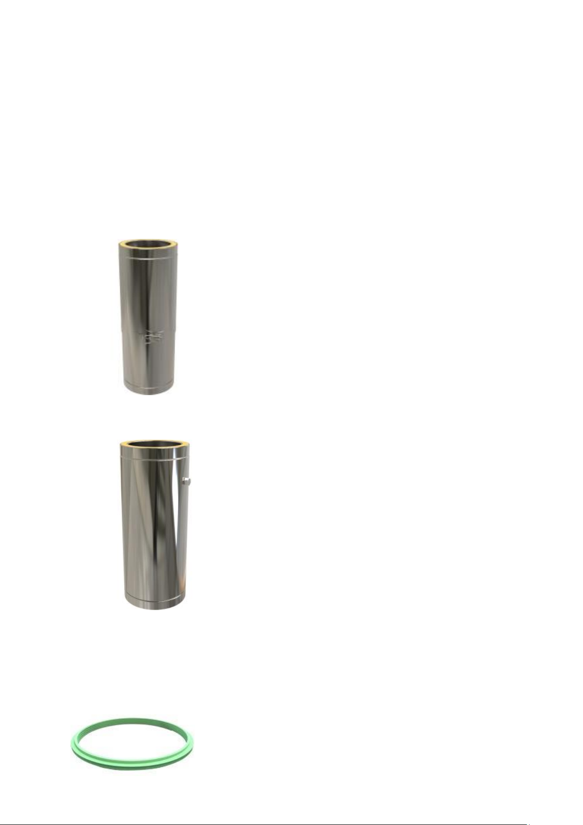
The Clearline AKW Chimney requires a 50mm clearance
to combustible material including timber joists stud walls,
plasterboard and plywood. On condensing flue systems, where
seals are fitted, the clearance to combustible material is
reduced to 20mm.
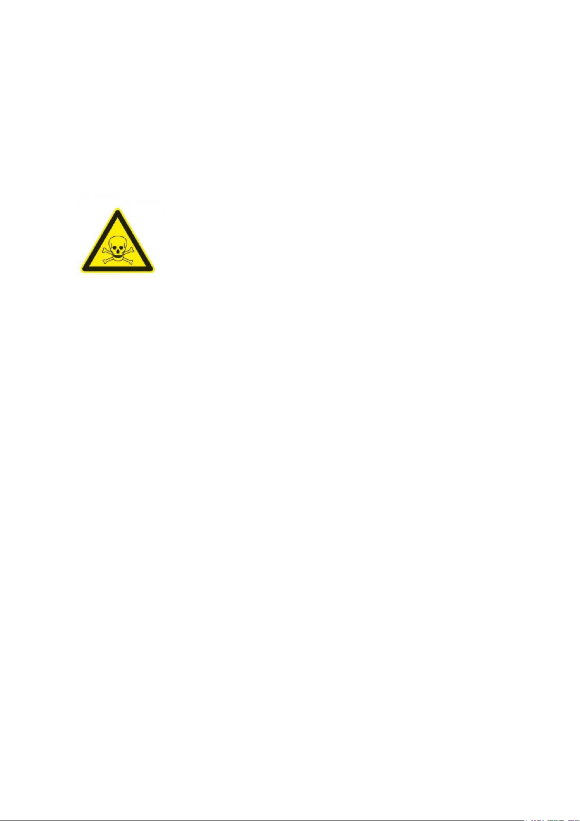
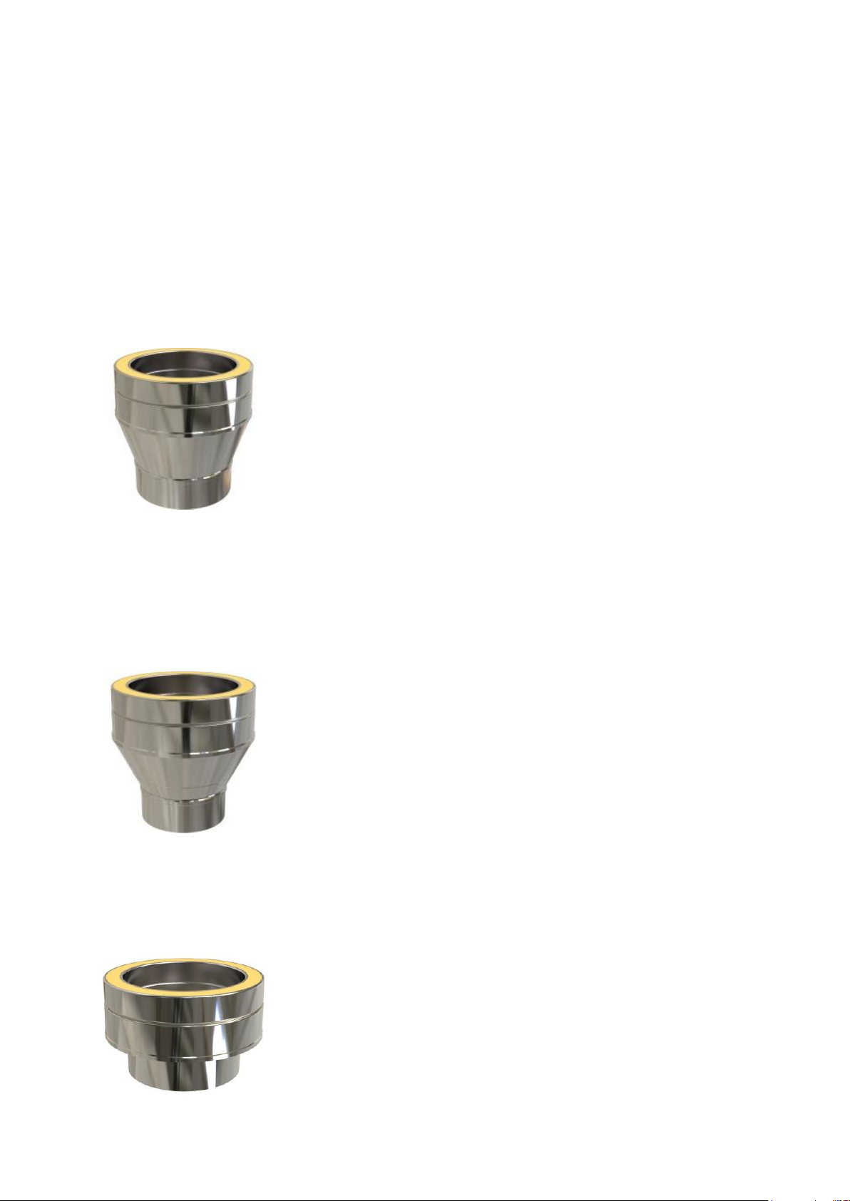
Clearline AKW is an open-ended system, each component
secured with a locking band which is included with every
component with a female connection.
There should be no more than 4 bends in a system. (A 90° Tee
on the back of the stove counts as 2 bends). If four bends are
used there should be sweeping access between the two offsets.
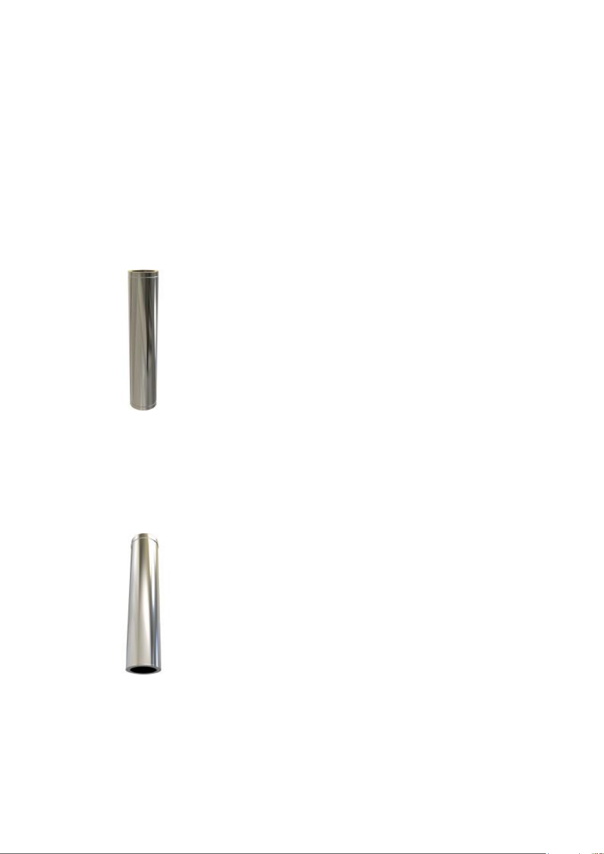
There should be no flue joins between a floor or ceiling joists or
rafters, with at least 150mm twin-wall flue projecting below
and above before an additional connection with twin wall.
The flue must not go more than 45° off vertical.
The minimum recommended height from top of stove to
termination is 4.5metres, however many stoves will run on a
shorter flue.
The minimum flue size for non defra approved stoves is
150mm.
The flue size must NEVER be smaller than the appliance outlet,
unless approved by stove manufacturer.
Flue needs to switch from single skin to twin wall at 425mm
below a ceiling.
Where the chimney passes through any part of the building,
(with the exception of the room where the appliance is
installed), where there is a risk of accidental human contact, i.e
a bedroom etc., or where there is a risk of contact with
combustible materials, the chimney must be enclosed in an
appropriate way to meet Building Regulations. This can be
achieved by boxing-in the chimney, or by the use of a
protective wire mesh frame in roof spaces etc. The minimum
distance of 50mm to any combustible material, including loft
insulation should always be observed and any enclosure should
be ventilated using the appropriate ventilated fire stops.
Twin wall should also be boxed-in in attic spaces. This can be
achieved with wire mesh to a minimum of 1200mm in height.
Single skin flue should be 3 times its diameter from
combustible material if not heat shielded. (i.e. 150mm pipe
should be 450mm from combustible materials).

5
It is recommended that the maximum horizontal offset should
not exceed 20% of the total length of the chimney.
All offsets should be supported above and below with the
appropriate support component i.e. ceiling, joist, wall or roof
support.
It is recommended that a vertical run of at least 600mm should
be allowed immediately above the appliance prior to any
change of direction.
To allow for expansion as the stove heats up, it is important
that the weight of the flue system is not carried by the
appliance. If the chimney is built from the stove upwards then
the flue lengths must be raised by 3-5mm before the supports
are fixed. A common practice would be to use small
combustible packers (eg. folded cardboard) placed in the flue
spigot to sit the first length or adaptor on. When the stove is lit
these will burn away while the fire-cement sets.
Twin wall lengths are designed to be assembled without the
use of any jointing compound.
If black twin wall flue is used straight off the stove then it is
important that the full length of the adaptor tail is recessed into
the flue spigot. This may require the adaptor tail to be cut
down.
NOTICE PLATE
The Notice plate for Clearline AKW should be marked up in indelible
ink and securely fixed in an unobtrusive but obvious position within
the building such as:
• Next to the electricity meter
• Next to the chimney installation
• Next to the water supply stop-cock

6
Typical internal flue system
Typical external flue system

7
CLEARLINE AKW COMPONENTS
*** Denotes flue diameter ie: 150mm = 02-150-001 or 30-150-001(for black)
Please be aware that not ALL components are available in Black, such as
components that are normally concealed.
STARTING COMPONENTS
SW-TW ADAPTOR Code:02-***-001
Tapered adaptor for connecting to traditional stoves with a flue collar, or going
from single skin to twin wall, same diameter. Eg. 150mm single skin to 150mm
twin wall. Working length 128mm.
SW-TW 100-125 INCREASING ADAPTOR Code:02-100-002
100mm single skin to 125mm twin wall.
SW-TW INCREASING ADAPTOR Code:02-125-002
Eg: 125mm single skin to 150mm twin wall.
SW-TW FLAT ADAPTOR Code: 02-***-005
Eg: for contemporary, European stoves, like Westfire, Opus, stoves without a
standard flue collar.

8
SW-TW FLAT INCREASING ADAPTOR Code:02-125-009
Eg: For connecting directly from 125mm outlet on European stove (without a
standard flue collar) to 150mm twin wall.
ADAPTOR TO FLEX Code:02-***-099
Used to convert from Twin wall insulated flue beneath, to flexible liner above.
Includes a locking band.
ADAPTOR FROM FLEX Code:02-***-101
Used to convert from Flexible liner beneath, to Twin wall insulated flue above.

9
FLUE LENGTHS
All flue lengths include a locking band.
1000MM LENGTH Code:02-***-010
Working length 957mm
500MM LENGTH Code:02-***-011
Working length 457mm
250MM LENGTH Code:02-***-012
Working length 207mm
100MM LENGTH Code:02-***-018
Working length 65mm
1000MM CONNECTING STARTER LENGTH Code:02-***-021
Working length 957mm –with integrated adaptor. This length allows the
Clearline Single Skin flue to socket up into the section by 325mm, then back
down to connect to the stove. This part allows the stove to be removed later
without dismantling the chimney system, so as to comply with building
regulations.

10
500-880MM ADJUSTABLE LENGTH Code:02-***-014
Adjustable lengths come with two locking bands –distance to combustibles
remains at 50mm, the same as all standard lengths.
Each adjustable length comes with an extra short length of rockwool which gets
compressed to ensure insulation continues throughout. Care must be taken to
ensure that when assembled to required length no air gaps are left.
There is a high-temp plastic seal in the adjustable length locking band to avoid
any movement once length has been adjusted to required height. The locking
band fits onto the lower lip of the pipe.
350-500MM ADJUSTABLE LENGTH Code:02-***-015
250-350MM ADJUSTABLE LENGTH Code:02-***-016
500MM TESTING LENGTH Code:02-***-019
Working length 457mm, including analysis port
PELLET GASKET Code:15-***-102
A rubber seal used on condensing installations to stop the condensates from
penetrating the flue. The Product Designation for Clearline AKW with seals fitted
for condensing appliances is:
EN1856-2 T200-P1-W-V2-L50040 0(20)

11
BENDS AND TEES
All bends and Tees are fully welded on the inside and outside and come with a
locking band. Please note - Flue pipe bends are measured in degrees from the
vertical plane. Roof pitches are also measured in degrees, but from the
horizontal plane. Ie, a 30 degree flue bend will not follow a 30 degree roof
pitch.
135 DEGREE TEE Code:02-***-034
Used when exiting a wall at 45 degrees, allowing sweeping access to the
external part of the flue system. Tee Cap has to be ordered separately. Two
locking bands are included.
90 DEGREE TEE Code:02-***-035
When using the rear outlet on a stove. Tee Cap has to be ordered separately.
TEE CAP Code:02-***-036
Used with 90 Degree and 135 Degee Tees

12
TEE CAP WITH DRAIN Code:02-***-037
For condensing systems or systems with an open terminal.
45 DEGREE BEND Code:02-***-031
30 DEGREE BEND Code:02-***-032
15 DEGREE BEND Code:02-***-033

13
SUPPORTING COMPONENTS
Clearline AKW Twin Wall can extend 1.5metres above the roof
without extra support.
JOIST SUPPORT Code:15-***-068
Flue support used on horizontal joists or timbers when passing into a cold roof.
It can be used on the floor in a loft to replace second ventilated ceiling support.
ROOF SUPPORT Code:15-***-067
This supports the flue as it passes roof rafters, pivoting to meet any roof pitch.
50-80MM WALL BAND Code:15-***-051
Provides lateral support, to be used every 1500 -2500mm
80-130MM WALL BAND Code:15-***-052
Provides lateral support, to be used every 1500 -2500mm

14
130-210MM WALL BAND Code:15-***-053
Provides lateral support, to be used every 1500 -2500mm
210-420MM WALL BAND Code:15-***-055
Provides lateral support, to be used every 1500 -2500mm.
CORNER WALL BAND 270-520MM
For corner installations to replace a standard wall band giving a balanced look.

15
STRUCTURAL LOCKING BAND Code:02-***-054
Increases the maximum unsupported height of the flue from 1.5m to 2.5m, one
should be used on the joint below the roof support, and on each joint above the
roof, except the termination, replacing the standard locking band.
FLOOR SUPPORT BAND/GUY WIRE BRACKET Code:15-***-069
The Floor Support Band sits on top of the upper ventilated ceiling support.
The Guy Wire bracket is used where there are guy wire attachment points on
three sides, otherwise a roof brace kit should be used.
ADJUSTABLE BASE SUPPORT 50-80MM Code:02-***-060
Used for external systems supporting up to 20metres of flue. Incorporates a
200mm flue length. This part supports the chimney up to 12metres above and
8metres below. Wall bands are required at 1.5 -2.5metre intervals, as the
situation requires.

16
ADJUSTABLE BASE SUPPORT 80-280MM Code:02-***-063
Used for external systems supporting up to 20metres of flue. Incorporates a
200mm flue length. This part supports the chimney up to 12metres above and
8metres below. Wall bands are required at 1.5 -2.5metre intervals, as the
situation requires.
TRUNCATED STACK PLATE Code:02-***-062
Used for truncated systems, changing from a flexible liner inside a masonry
chimney to Clearline AKW Twin Wall insulated flue above. Holes already drilled
in each corner for fixing the plate down. The flexible liner connection utilises
the screw fitting detail.
ROOF BRACE KIT Code:RBK
A roof brace can be used whenever there is need to stabilise the chimney above
roof level. Not available in black.

17
PENETRATION COMPONENTS
SOLID FIRESTOP PLATE Code:02-***-070
Mainly used in gas or oil installations. For solid fuel installations, can only be
used to go through a floor in a single storey building into a non-habitable cold
loft space.
WHITE VENTILATED FIRESTOP PLATE Code:02-***-073
Used when penetrating a ceiling or floor in a domestic installation. The Ceiling
Support Kit comprises of two of these and a Floor Support Band. Can be used
with the Ventilated Firestop Cover Plate. The pair of Ventilated Firestop Plates
can support 3metres of flue above the ceiling, and 1.5metres below.
WHITE FIRESTOP COVER PLATE Code:15-***-075
This is powder coated to match white ceilings. Used to cover existing Ventilated
Firestop Plate, still allowing enough free air around the flue and the boxing in
above. The plate includes magnets and spacers to ensure enough free air
movement.

18
WIDE ROUND FINISHING PLATE 0-30 DEGREE Code:15-***-108
150mm wide. Covers any gap to combustibles, or making good around flue as it
passes through ceilings or walls.
WIDE ROUND FINISHING PLATE 30-45 DEGREE Code:15-***-109
150mm wide. Covers any gap to combustibles, or making good around flue as it
passes through ceilings or walls.
WALL SLEEVE 45 DEGREE Code:15-***-100
Used when going through a wall at a 45 degree angle.

19
FLASHINGS
Traditional lead, nu-lead and aluminium flashings for tiled roofs, and EPDM
flashings for flat and profiled roofs –we have a full range of sizes available.
Please see website for details.
STORM COLLAR Code:15-***-082
Provides a skirt to deflect water. Positioned an inch or so above the flashing.
When fitting, a bead of silicone should be used round the top to seal.
TERMINATIONS
RAIN CAP Code:02-***-090
Must be used to prevent rain ingress. Includes a locking band.

20
ANTI -DOWNDRAUGHT COWL Code:02-***-091
Includes a locking band. Helps to prevent downdraft and rain entry. Used on
chimneys subject to strong prevailing winds, or where tall trees or buildings are
in close proximity.
SPINNING COWL Code:02-***-094
Regular maintenance is required for this type of cowl.
CONE TOP COWL Code:02-***-093
GAS COWL Code:02-***-092
For gas systems only
Table of contents
Popular Fan manuals by other brands

ProKlima
ProKlima RD-40B manual

Progress Lighting
Progress Lighting AirPro P2596 installation manual

Suntec Wellness
Suntec Wellness KLIMATRONIC CoolBreeze 9000 TOSlim+ manual

Mitsubishi Electric
Mitsubishi Electric Lossnay LGH-F300RX3-E Handbook

Eldom
Eldom COLUMBIA VAC WGC40N manual

ORIGO
ORIGO CF1515 instruction manual

aerauliqa
aerauliqa Quantum NEXT installation manual

S&P
S&P HTD-130 MR Installation manual and operating instructions

NMB-MAT
NMB-MAT DC Axial Fans FBA11J10M Specifications

Kendal Lighting
Kendal Lighting AC-21560 Installation and operation manual

Schweigen
Schweigen BR500ST installation guide

Bestron
Bestron ASV45ZR instruction manual