FireAngel Stove Guard SGEL-SN-1 User manual

STOVE GUARD
For indoor use only.
Do not use in a professional kitchen.
The Control Unit must be installed by an authorized electrician.
SGEL-SN-1-UserManual-A1
STOVE GUARD
SGEL-SN-1
MAIN MANUAL
Installation and Operating Instructions
INSTALLATION P. 4-13 USER GUIDE P. 14-23 TECHNICAL SPECIFICATIONS
P. 24-28
3
1 2

2
Thank You for choosing the FireAngel Stove Guard!
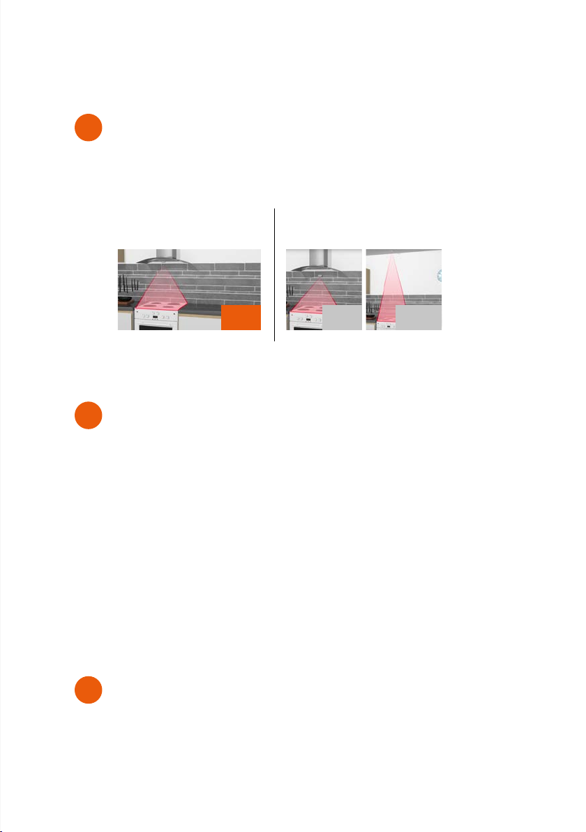
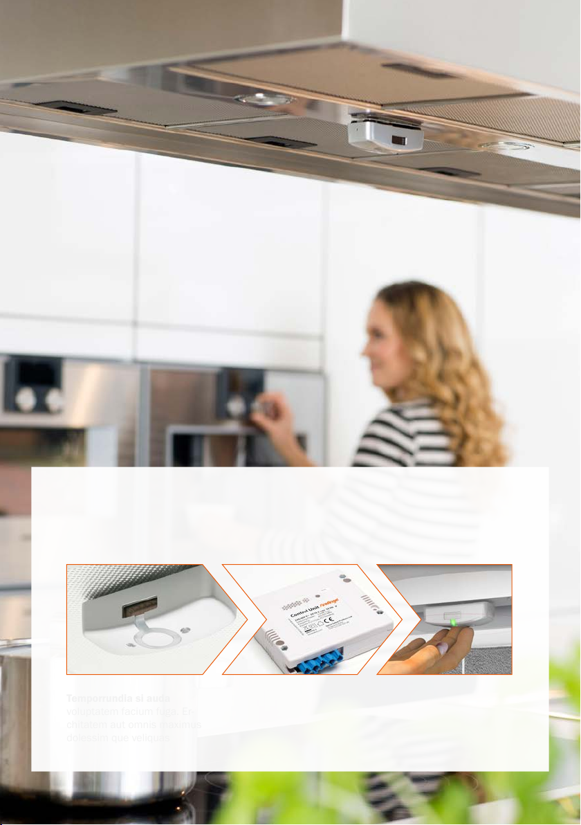
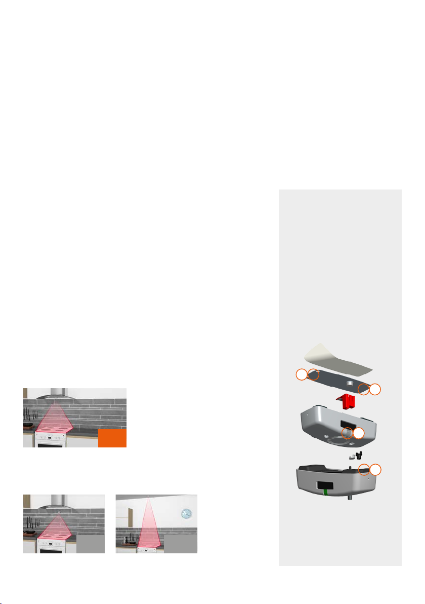
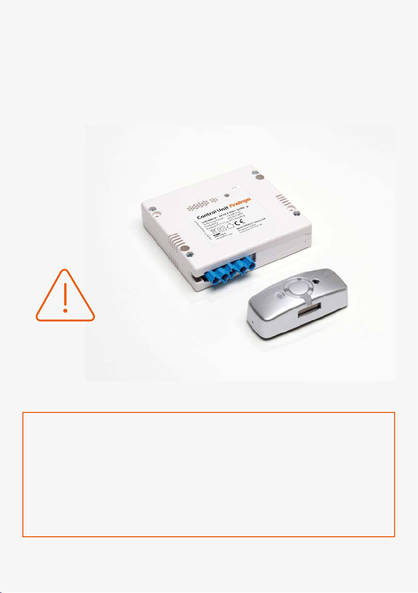
Stove Guard SGEL-SN-1 is a safety product for domestic kitchens. The
Stove Guard consists of the Intelligent Heat Sensor that monitors the
cooker, and the Control Unit that cuts the power if a dangerous situa-
tion occurs. Automatic fault diagnosis prevents the use of the cooker
if the Sensor is removed. The safety rules must be read before using
the product and must always be followed.
Safety rules
The Stove Guard does not cover all potentially dangerous
situations, but it makes the use of the cooker significantly
safer.
Never leave the cooker unattended.
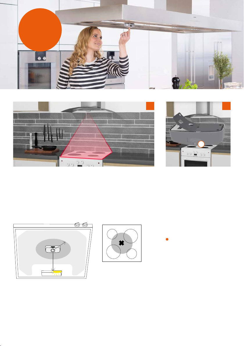
The Stove Guard can be used for all electric cookers from
0-90 cm wide. For wider cookers, contact the retailer.
Always check compliance with local regulations.
• For indoor use only.
• Do not use in a professional kitchen.
• Do not leave the cooker unattended after the pre-
alarm is reset.
• Do not hold the Heat Sensor closer to the ear than
15 cm. It can cause hearing damage when it emits
an alarm.
• Do not leave children alone with the product or any
of its parts or packaging. There is a risk of choking.
• Do not disassemble the product.
• Do not immerse the Sensor in water.
• The Stove Guard will not emit an alarm if the
temperature of the cooker is too low to identify a
dangerous situation, or if the cooker has an auto-
matic limitation of temperature increase.
• The Stove Guard does not cut all phases when the
cooker is switched off. It must never be used to turn
off the cooker’s power supply for service/repair.
• Do not short-circuit, charge, open or burn the
batteries. There is a risk of explosion.
The operating instructions, accessories and stickers must accompany the product. Follow the safety rules for safe
use of the Stove Guard. If you have questions about the product, ask a specialist or refer to FireAngel.co.uk

3
INSTALLATION 4-13
Installation of the Stove Guard 4
Installation of Intelligent Heat Sensor 5
Installation locations of Intelligent Heat Sensor 6-11
Installation of Control Unit 12
Function test 13
CONTENTS
1
2
3
Installation under cooker hood Wall mounting Ceiling mounting
USER GUIDE 14-23
Getting started with the Stove Guard 15
Read before using the Stove Guard 16-17
Avoiding false alarms 16
After alarm: Cookers with mechanical knobs 16
After alarm: Cookers with touch controls 16
Dislocation alarm 16
Silent alarm 16
Action in event of alarm 17
Other settings 18-19
Change the Sensor's sensitivity setting 18
Checking the Sensor's sensitivity setting 19
Reset the sensitivity to the factory settings 19
Pairing of devices 19
Carbon monoxide / smoke alarm detection 20-21
Frequently asked questions 22-23
TECHNICAL SPECIFICATIONS 24-28
The Stove Guard 25
Warranty 26
Disposal 26
Declaration of conformity 27
Cooker connection 28
P. 6-7 P. 8 - 9 P. 10-11
RECOMMENDED OPTIONAL

Temporrundia si auda
voluptatem facium fuga. Er-
chitatem aut omnis maximus
dolessim que veliquas
1
Installing the Stove Guard
To install correctly, follow the instructions.
STEP 1:
Installation of
Intelligent Heat Sensor
p. 5-11
STEP 2:
Installation of
the Control Unit
p. 12
STEP 3:
Function test
p. 13

5
Safety
In order for the Heat Sensor to function optimally and give an alarm at
the right time, it is crucial that the Sensor is properly positioned and that
the sensitivity is properly configured.
Sensitivity
The Heat Sensor’s sensitivity is factory-set for horizontal installation 45-
60 cm above the cooker.
The sensitivity must be adjusted if the installation height differs from
the factory setting. See page 19.
INSTALLATION
OF INTELLIGENT HEAT SENSOR
The best place to install the Intelligent Heat Sensor is horizontally, on the fan,
directly above the middle of the cooker. The Sensor can also be mounted on
a wall with an angle bracket or in the ceiling. One Sensor covers a cooker up
to 90 cm wide. Follow the instructions for correct installation.
Correct installation of
the Heat Sensor
During installation, the Sensor
should be placed on the
mounting plate to ensure
correct mounting with the
LED (A) facing out towards the
user. Place the Sensor parallel
to the plate. The metal pins
on each side of the mounting
plate (C) must each meet their
track on the short edges of the
Sensor (D).
INSTALLATION LOCATIONS
A
C
D
C
Note! Incorrect positioning of
the Sensor on the mounting
plate will cause disconnec-
tion of the cooker.
Installation under cooker hood
Wall mounting Ceiling mounting
P. 6-7
P. 8 - 9 P. 10-11
RECOMMENDED
OPTIONAL

6
A
Select the mounting location
Measure the installation height. The Heat Sensor should be centred
above the cooker, preferably within zone 1 (see the table). It can be
attached to the grease filter. The minimum distance to the lamp is 10
cm (5 cm for LED). Clean the surface well and dry it before mounting.
Mount the Heat Sensor
Attach the mounting plate while
the Sensor is on it.
Remove the protective foil from
the mounting plate. Attach the
Sensor with the lamp (A) facing
the user.
Remove the Sensor (one “beep”
may be heard). Press the
mounting plate firmly against
the surface so that the adhesive
tape is firmly attached.
1 2
1a
Zone 2 Zone 1
Radius 15 cm
Min 10 cm
Min: 5 cm for LED
Zone 1
Zone 1 is immediately
above the middle of the
cooker. Max 15 cm from
the centre.
1 INSTALLATION

7
COOKER HOOD
HORIZONTAL INSTALLATION UNDER COOKER HOOD
Allow the Heat Sensor to reach room temperature before use. The
power to the cooker must be switched off (fuse box). See the table
for the mounting location and follow the instructions from 1-4.
Starting the Sensor
Remove the red battery discon-
nection piece (B) and replace the
Sensor on the mounting plate.
Press in the Sensor cover (lamp
(A) flashes green).
Keep the battery disconnection
piece for future use.
Check installation height
Set the Sensor’s sensitivity level according to the mounting height.
The factory setting for sensitivity level is 45-60 cm above the cooker.
If the installation height is not between 45-60 cm sensitivity needs to be
set manually (see the table underneath and page 18, or watch the film
on sensitivity configuration).
3
DISTANCE FROM COOKER
TO SENSOR
MOUNTING LOCATION SENSITIVITY LEVEL CONFIGURATION
0-60 cm wide
cooker
61-90 cm wide
cooker
Sensitivity Acknowledgement "beep(s)"
81 - 100 cm *Zone 1 and 2 Zone 1 3 presses
77 - 80 cm
Zone 1 Zone 2
(Note! See EN
requirement, page
20, point 4)
Zone 1
(Note! See EN
requirement, page
20, point 4)
4 presses
71 - 75 cm 5 presses
65 - 70 cm 6 presses
61 - 64 cm 7 presses
45 - 60 cm Factory setting 8 presses
* For wall mounting lower than 80 cm and horizontal mounting 81-100 cm below the fan,
the sensor will not in all cases meet all EN standard requirements.
B
A
Watch the film on sensitivity
configuration (48 sec.)
goog.gl/eS3oZF
4

8
A
Select the mounting location and mount the bracket
Wall mounting requires a bracket, which is sold separately (see page
28). The bracket is fastened on the wall using adhesive tape or screws.
Clean the surface well and dry it.
See the mounting instructions in the bracket package. Make sure that
the bracket is positioned correctly and that the angle is adjusted, so that
the Sensor faces towards the centre of the cooker.
Mount the Heat Sensor
Attach the mounting plate while
the Sensor is on it.
Remove the protective foil from
the mounting plate. Attach Heat
Sensor with the LED (A) facing
the user.
Remove the Sensor (one “beep”
may be heard). Press the
mounting plate firmly against the
bracket, so that the adhesive
tape is firmly attached.
2b
1
Mounting height on the wall above the cooker
Max 90 cm wide cooker.
Recommended: 80 cm
Alternatively: 65-79 cm
See the mounting instructions in the bracket package.
1 INSTALLATION
2
1b

9
WALL
WALL MOUNTING WITH BRACKET
Allow the Heat Sensor to reach room temperature before use.
See the table and follow the instructions from 1-4.
Starting the Sensor
Remove the red battery discon-
nection piece (B) and return
Heat Sensor on the mounting
plate.
Press the Heat Sensor cover
(LED (A) flashes green).
Keep the battery disconnection
piece for future use.
Set sensitivity level
Set the Heat Sensor’s sensitivity level according to the table below.
See page 18.
MOUNTING HEIGHT SENSITIVITY LEVEL CONFIGURATION
Sensitivity Acknowledgement “beep(s)”
80 cm (recommended) 3 presses
70-79 cm *3 presses
65-69 cm *4 presses
3
B
A
Watch the film on sensitivity
configuration (48 sec.)
goog.gl/eS3oZF
3 4
* For wall mounting lower than 80 cm and horizontal mounting 81-100 cm below the fan,
the sensor will not in all cases meet all EN standard requirements.

10
A
Replace lens
Carefully lift the lens with a
screwdriver. Press down the
IR lens extension (included)
as shown in the picture. The
extension should point upwards
at an angle of 90°. If it does not
point straight up, it is set 180°
the wrong way.
Select the mounting
location
The sensor must be placed
directly above the cooker or
at an angle with a mounting
bracket (sold separately). Use a
weight and a string, or Precision
Installation Tool SAI500-PIT, to
find the cooker’s centre point, or
see the mounting instructions in
the bracket package.
Clean the surface well and dry it.
Recommended position
Immediately above the middle of
the cooker. Max 5 cm from the
centre.
Mount the Heat Sensor
Attach the mounting plate while
the Sensor is on it.
Remove the protective foil from
the mounting plate. Attach the
Sensor with the LED (A) facing
the user.
Remove the Sensor (one “beep”
may be heard). Press the
mounting plate firmly against the
surface for at least one minute
so that the adhesive tape is
firmly attached.
1 2 3
1 INSTALLATION
1c

11
Allow the Heat Sensor to reach room temperature before use. See the
table for the mounting location and follow the instructions from 1-5.
CEILING
Starting the Sensor
Remove the red battery discon-
nection piece (B) and replace the
Sensor on the mounting plate.
Press the Sensor cover (LED (A)
flashes green).
Keep the battery disconnection
piece for future use.
Set sensitivity level
Set the Sensor's sensitivity level to 1. See page 18.
MOUNTING LOCATION SENSITIVITY LEVEL CONFIGURATION
Mounting height above the
cooker
0-60 cm wide cooker Sensitivity Acknowledgement “beep(s)”
150-180 cm Recommended: Immediately above
the middle of the cooker.
Alternatively: Farther out into the
room with bracket. See the bracket
package for mounting.
1 press
Mounting height above the
cooker
0-90 cm wide cooker
181-200 cm Recommended: Immediately above
the middle of the cooker.
Alternatively: Farther out into the
room with bracket. See the bracket
package for mounting.
4
B
A
See film:
goog.gl/eS3oZF
5

12
It is a statutory requirement that the Control Unit is installed by an authorized electrician, except for plug
& play versions. The power to the cooker must be disconnected during the entire installation.
Disconnect the power
Switch off the power from the
fuse box.
Note! Do not turn on the fuse be-
fore the Sensor is set and ready
for a function test.
Connect to the Control Unit
Connect according to the wiring diagram,
see page 28.
CONTROL UNIT
INSTALLATION OF CONTROL UNIT
1 2
POWER
OFF
1 INSTALLATION

13
The installation is completed when the test has been passed.
The Sensor will then give an alarm that can save lives and property.
The operating instructions, accessories and stickers must accompany
the product.
Return the power
Connect the power.
Switch on the power from the
fuse box.
Perform function test
Wait 30 seconds. Press and hold
the Sensor cover until the Sensor
emits a “beep” ( ) and the red
LED flashes.
The Control Unit will switch off
the cooker and give an alarm sig-
nal every 5 seconds. The Sensor
will also emit a test alarm after a
few seconds.
Note! Check that there is no
power connected to the cooker
(or that there is no voltage in the
Control Unit).
Reset the alarm
Reset the test alarm by pressing
once on the Sensor cover.
Check that the cooker can be
turned on (or that there is volt-
age in the Control Unit).
If the Sensor does not respond
or if the test alarm cannot be
reset, see page 22, points 5
and 6.
FUNCTION TEST
POWER
ON 1 2 3
Installation is now ready.
Wait 15 minutes before using the cooker.

14
2

15
The cooker is ready for use after 15 minutes from completing the
installation of the Stove Guard. However, at the beginning, it may start
to signal during normal cooking. This is because the Intelligent Heat
Sensor learns what are the normal temperature ranges during cooking.
GETTING STARTED
WITH THE STOVE GUARD
The Sensor may start making
short “beeps” every couple of
seconds while it is being used
(“pre-alarm”).
Press the cover to indicate that it
is not a dangerous situation.
The Sensor has then learned
more about your cooking habits
and you can continue cooking.
LIESIVAHTI SGK510
OPAS KÄYTTÄJÄLLE
Matalat asennuskorkeudet
Älylämpöanturi alle 90 cm lieden yläpuolella
Käytön alussa
Liesivahti on heti valmis käyttöön. Käytön alkuvaiheessa se saattaa kuitenkin
hälyttää normaalin ruoanlaiton aikana. Tämä johtuu siitä, että Liesivahti
mukautuu asteittain erilaisiin ruoanlaittotapoihin.
Kun Liesivahdin asetukset ovat valmiit (yleensä n. 1–5 hälytyskerran jälkeen), se
ei enää hälytä normaalin ruoanlaiton aikana.
www.innohome.com
Lämpöanturin kannen painaminen ennakkovaroituksen aikana
( ) katkaisee hälytyksen ja saa Liesivahdin
muuttamaan herkkyyttään automaattisesti.
Liesivahti tarkkailee lieden lämpötilaa ja sen muutoksia.
Vaaratilanteessa Liesivahti hälyttää ja katkaisee lieden virran
automaattisesti.
SGK510-GuideForUser-FI-revC-ver1
Normaalitoimintojen merkkiäänet
Merkkiääni Tarkoittaa Toimi näin
Älylämpöanturi:
lyhyt 'piip' parin sekunnin
väliajoin (ennakkovaroitus),
sitten nopea 'piip, piip, piip'
Lämpöanturi on
tunnistanut vaaratilanteen.
Ennakkovaroitus annetaan
ennen lieden kytkemistä
pois päältä. Nopea, jatkuva
piipitys tarkoittaa että liesi
on kytketty pois päältä.
Jos hälytyksen aiheutti normaali
ruoanlaitto, paina anturin kantta
kerran ennakkovaroituksen
aikana.
Ohjainyksikkö:
lyhyt suriseva ääni viiden
sekunnin välein
Liesi on kytketty pois päältä
jokin aika sitten.
Käännä lieden säätimet ensin
nollaan, sitten paina lämpöanturin
kantta kerran. (Liesissä, joissa
on kosketusohjaus, riittää
pelkkä lämpöanturin kannen
painaminen.) Jos liesi ei mene
takaisin päälle, katso käsikirjan
UKK (kappale 4) kysymys 4.1.
Ohjainyksikkö:
jatkuva suriseva ääni
Liesi on liian kuuma takaisin
päälle kytkettäväksi.
Odota, että liesi jäähtyy
turvalliselle tasolle.
Valinnaiset ominaisuudet
Ohjainyksikkö:
lyhyt suriseva ääni kahden
sekunnin välein (älyajasti-
men ennakkovaroitus)
Älyajastin kytkee lieden pois
päältä minuutin päästä.
Paina lämpöanturin kantta kerran,
jotta liettä ei kytketä pois päältä.
Ohjainyksikkö:
kaksi lyhyttä surisevaa ääntä
(kun käyttölukko on juuri
otettu pois päältä)
Liettä voi nyt käyttää.
Vikamerkkiäänet
Merkkiääni Tarkoittaa Toimi näin
Ohjainyksikkö:
lyhyt ja pitkä suriseva ääni,
vaihdellen viiden sekunnin
välein
Automaattinen
vikadiagnostiikka on
kytkenyt lieden pois päältä
väliaikaisen häiriön tai
järjestelmän vian takia.
Käännä lieden säätimet ensin
nollaan, sitten paina lämpöanturin
kantta kerran. (Liesissä, joissa
on kosketusohjaus, riittää
pelkkä lämpöanturin kannen
painaminen.) Jos tämä ei hiljennä
merkkiääntä, katso käsikirjan UKK
(kappale 4), kysymys 5.1.
Ohjainyksikkö:
suriseva ääni puolen tunnin
tai tunnin väliajoin
Lieden tunnistuksessa on
tapahtunut virhe.
Katso käsikirjan UKK (kappale 4),
kysymys 5.2.
Älylämpöanturi
(ja ohjainyksikkö):
merkkiääni kerran
minuutissa
Älylämpöanturi on
käyttöikänsä lopussa.
Lämpöanturi tulee vaihtaa
uuteen (katso käsikirjan
kappale 6). Lämpöanturin
kannen painaminen viivästyttää
hälytystä 12 tunnilla. Kun paristo
on loppunut, liettä voi käyttää
ainoastaan viisi minuuttia
kerrallaan (EN-standardin
määrittelemä vaatimus).
Mitä vikamerkkiäänet tarkoittavat?Mitä merkkiäänet tarkoittavat?
Älylämpöanturi on lieden yllä: merkkiääni on korkea ’piip’.
Ohjainyksikkö on lieden takana: merkkiääni on matalampi surina.
SGK510-GuideForUser-FI-revC-ver1 v5.indd 1-3 07/04/2016 15:34

16
READ BEFORE
USING THE STOVE GUARD
Avoiding false alarms
Use a pan that covers the entire hotplate to prevent
false alarms. Using a lid is recommended.
Always use the cooker hood if you have one.
If you have a freestanding cooker or an oven under
the hob, the oven knobs must also be turned off
once the power supply to the cooker or hob has been
switched off by the alarm.
After alarm
Mechanical knobs
If the Stove Guard has turned the cooker off, first
turn all cooker knobs to ‘0’, then press the Heat
Sensor cover once. After this, the cooker can be
used normally.
Touch controls
If the Stove Guard has turned the cooker off, press
the Heat Sensor cover once. After this, the cooker
can be used normally.
In some cases you must wait until the cooker has
cooled down to continue the use.
Dislocation alarm
Removing the Heat Sensor from the mounting plate
turns the cooker off. Returning the Sensor back to
the mounting plate returns the power to the cooker.
Opening and closing the Intelligent
Heat Sensor cover
Use the tip of a
screwdriver to carefully
detach the cover, one
end at a time.
To put the cover back, put both
ends in at the same time.
Make sure that the black round
Sensor goes through the opening
of the cover.
Silent alarm
The Heat Sensor alarm signal can be turned off for
users that find it disturbing.
For low installations (Heat Sensor installed lower
than 90 cm above the cooker top): since the user
will not notice the Heat Sensor pre-alarm signal and
therefore will not be able to use the learning sensi-
tivity feature, it is recommended to decrease Heat
Sensor's sensitivity by one level, see page 18.
Procedure
Open the cover. Turn the DIP switch 2 to 'off' position
(the image shows the switch in 'on' position). Place
the cover back according to instructions.
2 USER GUIDE
off on
off on
1
2

17
Heat Sensor
4 “beeps” with 1-second
interval.
Dislocation Alarm
The Sensor is removed
from the mounting
plate.
Return the Sensor on the mounting plate with the LED
facing the user.
Heat Sensor
Short “beeps” with a few
seconds’ interval.
...
Pre-Alarm
The Sensor alerts of
danger for 20 seconds
before disconnecting
the cooker.
If the alarm was triggered during normal cooking: press
the Sensor cover once while the pre-alarm sounds. The
alarm is turned off and the sensitivity adjusts slightly.
Heat Sensor
Many quick “beeps” followed
by a long very loud sound.
Switch-off Alarm
The cooker is switched
off.
Press the Sensor cover once to return the power to the
cooker. Make sure that the switches are set to “0” in
case of a fire hazard or if you leave the cooker.
Control Unit
Short “ring” with 5-second
intervals.
No power
The power to the cooker
has been cut off.
Make sure that the switches are set to “0” in case of
a fire hazard or if you leave the cooker. Wait until the
cooker has cooled down after the cooker has been dis-
connected or press the Sensor cover once to reconnect
the cooker. If the cooker cannot be switched back on,
see FAQ, question 9, page 23.
Control Unit
Continuous "rings".
No power
The cooker is too hot
for the power to be
turned back on.
Make sure that the switches are set to “0” in case of a
fire hazard or if you leave the hob. Wait until the cooker
has cooled down and the Control Unit emits a short
“ring” with 5-second intervals, as described in the sec-
tion above, or press the Sensor cover once to reconnect
the cooker. If the alarm does not stop, follow the instruc-
tions on page 23, FAQ question 9, and press again.
Control Unit
Short and long “ring” with
10-second intervals.
No power due to
Auto-diagnostics Alarm
The cooker has been
disconnected due to a
temporary fault (auto-
matic error diagnosis).
Make sure that the switches are set to “0” in case of
a fire hazard or if you leave the cooker. Wait until the
cooker has cooled down or press the Sensor cover
once to reconnect the cooker. If the cooker cannot be
switched back on, see FAQ, question 3, page 22.
Heat Sensor
One “beep” per minute.
Battery Alarm
The Sensor has a low
battery.
The Sensor battery has run out and the Sensor needs
to be replaced. Pressing once on the Sensor cover
delays the alarm for 12 hours. When the batteries
have been used up, the cooker can only be used for 5
minutes at a time (EN requirement).
Control Unit
One “ring” per minute.
Battery Alarm
The Sensor has a low
battery.
The Sensor battery has run out and the Sensor needs
to be replaced. Pressing once on the Sensor cover
delays the alarm for 12 hours. When the batteries
have been used up, the cooker can only be used for 5
minutes at a time (EN requirement).
Action in event of alarm
The cooker will automatically be ready for use after the Stove Guard has detected
that the hazardous situation is over, and all the switches are set to “0”.
See the alarm overview below for actions.

18
Change the Sensor’s sensitivity settings
Due to the differences in the kitchen environment, the sensitivity level
of the Sensor may have to be set manually.
off on
off on
If the battery disconnection piece is missing
A screwdriver can be used if the battery disconnection piece is
missing. Carefully press the button on the underside of the Sensor.
1. Remove the Sensor from the mounting plate
The Sensor emits 4 “beeps” ( ). The cooker is turned off.
2. Adjust the sensitivity
3. Confirmation of setting
After 5-15 seconds, the Sensor will confirm the sensitivity setting with the same number of “beeps”.
In case of error, start from step 2 again.
4. Activate the Sensor
Return the Sensor correctly on the mounting plate. Make sure it fits well. See page 5.
Note! Note! If the Stove Guard is installed for the first time, installation must be completed
with a function test. See page 13. The Sensor’s sensitivity can be checked or reset to the
factory setting. See page 19.
Place the Sensor on the table (as shown in the picture).
Press and hold in until 2 “beeps” ( ) are heard.
Press with 1-second interval
according to installation
instructions on pages 7-11,
depending on the installa-
tion location.
21
“BEEP” .... “BEEP”
2 USER GUIDE
OTHER SETTINGS

19
Pairing of devices
Checking the Sensor’s
sensitivity setting
1. Remove the Sensor from the
mounting plate. (The Sensor
gives 4 “beeps” ( ) and
the cooker is switched off.)
2. Press and hold the Sensor
cover (approx. 10 sec.) until two
“beeps” ( ) are heard.
3. After a moment, the sensor
beeps to indicate the configured
sensitivity. Unadjusted sensor’s
sensitivity setting is level 8, and
when checking the level, the
sensor gives a set of “beeps” as
follows: 8 - 8 - 5 - 8. If the sen-
sitivity was adjusted to level 3,
the sensor would give “beeps”:
3 - 3 - 5 - 3.
Acknowledgement “beep” factory
setting (unadjusted Sensor):
8 + 8 + 5 + 8 “beeps”.
Reset the sensitivity to
the factory setting
1. Remove the Sensor from the
mounting plate. (The Sensor gives 4
“beeps” ( ) and the cooker
is switched off).
2. Insert the battery disconnec-
tion piece (B) into the hole on the
underside of the Sensor. Press the
disconnection piece and the cover
against each other and hold in for
about 5 seconds.
3. Release the hold. (The Sensor emits a “beep” ). Remove the battery
disconnection piece and store it for future use.
4. Press and hold the Sensor cover until you hear 3 separate “beeps”
( ).
5. Return the Sensor to its position.
The units are already paired at the factory. When
replacing the Heat Sensor or Control Unit, the devices
must be paired again.
Note! The Heat Sensor must be
placed on the mounting plate
during pairing.
1. Check that the cooker is con-
nected to the power supply.
2. Press and hold the reset but-
ton on the Control Unit for 20
seconds (see picture). While
pressing, the Control Unit will
emit some clicks and buzzes.
The Control Unit is now ready
to be paired.
3. Press and hold the Heat
Sensor cover until the Sensor
emits a “beep” ( ) and a
red LED flashes. The Control
Unit makes a buzzing sound
and the Heat Sensor emits a
“beep” ( ).
4. After 5 seconds, the Heat
Sensor gives an alarm
(“beeps” and continuous
beeping). The Control Unit
and Sensor are now success-
fully paired.
5. Reset the test alarm by press-
ing once on the Sensor cover.
Check that the cooker can be
turned on. If the Sensor does
not respond or if the test
alarm cannot be reset, see
FAQ, page 22, points 5 and 6.
B
Reset
button

20
off on
off on
Remove the Sensor from the mounting plate. (Wait until the
Sensor emits four “beeps” ( ) and the cooker is
turned off.)
Put the battery disconnection piece into the space on the under-
side of the Heat Sensor (see image).
Hold the Heat Sensor in your hand and press the disconnection
piece and the cover towards each other and hold for about 5
seconds. Release your hold (the Sensor emits a “beep” ). Then
press the disconnection piece and the cover towards each other
again and hold for about 5 seconds. Release your hold (the
Sensor emits a “beep” ) and remove the battery disconnection
piece. If you have lost the disconnection piece, you can use a
screwdriver instead (see image).
Press the Heat Sensor cover once. The Sensor will now emit
“beeps”confirming its new setting: one “beep” ( ) signifies that
the Audible Alarm Detection is activated, two “beeps” ( )
signifies that the feature is deactivated.
Return the Heat Sensor to the mounting plate and press its
cover once.
Carbon monoxide / smoke alarm detection
1
3
2
4
The carbon monoxide / smoke alarm must be placed within 5
metres of the Control Unit. The Stove Guard is compatible with
virtually all alarms, but ensure correct alarm recognition by
testing the system first. If you wish to deactivate the feature
later, carry out the same procedure again.
2 USER GUIDE
Other manuals for Stove Guard SGEL-SN-1
1
Table of contents
Popular Security Sensor manuals by other brands

Linear
Linear NAPPIR01 installation instructions

Collision Sentry
Collision Sentry Corner Pro Instructions for installing and using

RKI Instruments
RKI Instruments Eagle Series instruction manual

Velleman
Velleman PIR416 user manual

Busch-Jaeger
Busch-Jaeger Busch-Wachter 220 MasterLINE 6847 Series quick start guide

Dr. Smart
Dr. Smart Inverter Air-Conditioner Detector Operation manual