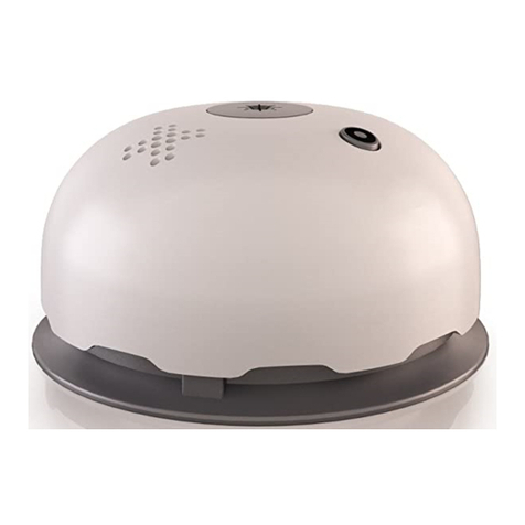
FireBrand CQR-338-2 User manual

Page 1of 2
CQR338-140820 REV. 3
CQR338
Conventional Photoelectric Smoke and Heat
Detector
Installation, Testing &
Maintenance Instructions
1. TYPICAL WIRING DIAGRAM
Figure 1 below shows a typical wiring diagram for a
2-wire multiple device detector system.
DO NOT PLACE LINKS BETWEEN THE WIRING POSITIONS OF
TERMINALS 2 AND 5 TO PROVIDE POWER SUPERVISION
Figure 2 below shows the typical wiring diagram for a
4-wire multiple device detector system.
DO NOT PLACE LINKS BETWEEN THE WIRING POSITIONS OF
TERMINALS 2 AND 5 TO PROVIDE POWER SUPERVISION
IMPORTANT WARNING
TO PREVENT DETECTOR CONTAMINATION AND
SUBSEQUENT WARRANTY CANCELLATION, THE
SMOKE DETECTOR MUST REMAIN COVERED UNTIL
THE AREA IS CLEAN AND DUST FREE.
2. INSTALLING THE BASE
1. To ensure the correct installation of the detector head
to the base, all the wires should be correctly installed:
(A) Position all the wires flat against terminals.
(B) Fasten the wires away from connector terminals.
2. If you used a jumper wire to connect the poles of
terminal 2 and 5 when testing the detector loop
continuity, be sure to remove the jumper wire prior to
the installation of the detector head.
3. The end-of-line device shown in figure 1 should be
compatible with the control panel.
4. Open area smoke detectors are intended for mounting
on a ceiling or a wall in accordance with the fire
standard in your country.
5. The base of the smoke detector can be mounted
directly onto an electrical junction box such as an
octagonal (75mm, 90mm or 100mm), a round (75mm),
or a square (100mm) box without using any type of
mechanical adapter.
3. ADJUSTING THE RELAY FOR NC/NO
(4 wire version only)
The normal condition for the relay is “normally closed”
(NC).
To adjust the normal condition of the relay to “normally
open”(NO),
a. Remove the 2 screws beneath the label on the back
of the detector head.
b. Insert a screwdriver into the rectangular hole located
on the side between the front cover and base and
rotate to remove the front cover.
c. Refer to figure 3. There is a jumper head next to the
relay on the PCB. Remove the jumper head and
reinsert it in the NO position.
d. Carefully replace the front cover and refit the screws
Relay contact rating:
1A@30VDC
0.5A@125VAC,
4. INSTALLING THE HEAD
1. Align the alignment mark on the detector head to the
short alignment mark on the base as shown in
Figure 4.
2. Place the detector head onto the base and twist
clockwise to secure it.
3.Do not install the detector head until the area is
thoroughly cleaned of construction debris, dusts, etc.
(The maximum number of detectors installed on the
same zone/circuit is 30, this maybe lower depending
on the local regulation)
+
-
Control
Panel
Power to
detectors
First/Next detector base
Last detector base
Zone/Circuit
connections
EOL Power
supervisor relay
5
2
6
1
3
4
5
2
6
1
3
4
+
+
+
-
-
EN54 listed
compatible
control panel
Zone
Loop
Connections for
Remote Indicator
First/Next detector base
Last detector base
5
2
6
1
3
4
EOL
Device
-
+
5
2
6
1
3
4
+
-
+
-
-
+
+
+
-
-
Control
Panel
Power to
detector
5
2
6
1
3
4
5
2
6
1
3
4
First detector base
Last detector base
Zone / Circuit
connections
-
+
+
+
-
-
Control
Panel
Power to
detector
5
2
6
1
3
4
5
2
6
1
3
4
First detector base
Last detector base
Zone / Circuit
connections
-
+
+
+
-
-
Control
Panel
Power to
detector
5
2
6
1
3
4
5
2
6
1
3
4
First detector base
Last detector base
Zone / Circuit
connections
See section 3 to configure the output type
the default setting is Normally Closed
Smoke Chamber
Relay
Jumper setting
LED
Detector head
LED
Base
Short alignment mark
Long alignment mark
Rectangular
Opening here
Figure 4. Placing the detector head onto base
Figure 3. Schematic of detector structure
When front cover is open.
-

Page 2of 2
CQR338-140820 REV. 3
5. TESTING
1.All the alarm signal devices, releasing devices and
extinguisher systems should be disabled during the
test period and must be re-enabled immediately at the
conclusion of testing.
2.After energising the detector head for approximately
one minute, check to see the indicator green LED
flashing once every 3~5 seconds (this may be difficult
in strong light as the flash is only dim). If green LED
fails to flash, it indicates the non-functioning of the
detector or faulty wiring. Re-check the wiring or replace
the detector if necessary.
SMOKE SENSOR TESTING
Allow smoke from a test smoke aerosol to enter the
detector-sensing chamber for at least 2-3 seconds.
When sufficient smoke has entered the chamber, the
detector will signal an alarm, this being visible by the
continuous illumination of the LED. Reset each detector
and/or control unit before attempting to test any
additional detectors on the same zone. If the alarm fails
in during this step, it indicates a defective unit, which
requires service/replacement.
HEAT SENSOR TESTING
The detector to be tested should be subject to a flow of
warm air at a temperature of between 65°C and 80°C or
by using a dedicated heat detector tester.
Proceed as follows:
a. Switch on the warm airflow and check that
temperature is correct and stable.
b. From a distance of several inches, direct the
airflow at the guard protecting the thermistor.
The detector should alarm within 30 seconds
c. Upon alarm immediately remove the heat
source and check that the red LED of the
detector is illuminated. Reset the detector from
the control panel.
d. If detector fails to go into alarm mode within 30
seconds it is too insensitive and needs to be
returned to the distributor for servicing.
3. If using a dedicated heat detector tester following the
manufacturer’s instructions.
4. After testing, check that the system is set for normal
operation and notify the appropriate authorities that the
testing operation is complete and the system is active
again.
NOT SUITABLE FOR INSTALLATION IN AREAS
WHERE AIR VELOCITIES EXCEED 300 ft/min
6. MAINTENANCE
The recommended minimum requirement for detector
maintenance consists of an annual cleaning of dust from
the detector head by using a vacuum cleaner.
CAUTION: DO NOT ATTEMPT TO DISASSEMBLE THE
FACTORY SEALED SMOKE DETECTOR. THIS
ASSEMBLY IS SEALED FOR YOUR PROTECTION AND
IS NOT INTENDED TO BE OPENED FOR SERVICING BY
USERS. OPENING THE DETECTOR CHAMBER WILL
VOID THE WARRANTY.
SPECIFICATION
Model
2/4
wire
Thermal
Voltage
DC
Standby
Current
(Max.)
Alarm
Current
(Max.)
Surge
Current
(Max.)
Star-Up
Time
(Max.)
Permissible
Current
(Max.)
LED Flash
Frequency
Remote Led
Option
Alarm
contact
Standardbase
model number
Deep base
model number
CQR-338-2
2
28/12V
90μA
70mA
120μA
60
Seconds
80mA
3-5 Seconds
—
—
772912
882912
CQR-338-2L
2
28/12V
90μA
70mA
120μA
60
Seconds
80mA
3-5 Seconds
Yes
—
774912
882912
CQR-338-4-12
4
12V
320μA
35mA
120μA
60
Seconds
80mA
3-5 Seconds
—
FormA
774912
882912
CQR-338-4-24
4
24V
320μA
35mA
120μA
60
Seconds
80mA
3-5 Seconds
—
FormA
774912
882912
CQR-338-2H
2
57°C
28/12V
100μA
70mA
130μA
60
Seconds
80mA
3-5 Seconds
—
—
772912
882912
CQR-338-2HL
2
57°C
28/12V
100μA
70mA
130μA
60
Seconds
80mA
3-5 Seconds
Yes
—
774912
882912
CQR-338-4H-12
4
57°C
12V
320μA
35mA
130μA
60
Seconds
80mA
3-5 Seconds
—
FormA
774912
882912
CQR-338-4H-24
4
57°C
24V
320μA
35mA
130μA
60
Seconds
80mA
3-5 Seconds
—
FormA
774912
882912
Remarks: H=heat/ L= Remote LED indicator output
LIMITED WARRANTY STATEMENT
ALL CQR PRODUCTS CARRY OUR STANDARD WARRANTY, PLEASE SEE CQR TERMS AND
CONDITION FOR FULL DETAILS.
CQR Security
125 Pasture Road, Moreton, Merseyside,
United Kingdom, CH46 4TH
Tel: - +44(0)151 606 1000 Fax: - +44(0)151 606 1122
Technical Support: - +44(0)151 606 6311 web:- www.cqr.co.uk Technical Support:- +44(0)1516066325
2531
web:- www.cqr.co.uk Technical Support:- +44(0)1516066325
This manual suits for next models
7


