FireClass FC410RIM User manual

FireClass FC410RIM
Fixing Instructions Doc. version 4.0 1/12
FC410RIM
Módulo entrada de contactos
Modulo relè
Relay interface module
Ausgangselement, nicht überwacht
Best.-Nr. 568.800.703
DEUTSCH
Anwendung
Das FC Ausgangselement FC410RIM stellt
einen potentialfreien Relaisausgang (Umschalter
24 V DC, 2 A) zur Verfügung. Es kann mit
FireClass Console auf zwei Betriebsarten ein-
gestellt werden:
Türsteuerung
Steuerung
Technische daten
Adresseinstellung
Per Auslieferungszustand ist die Adresse stan-
dardmäßig auf 255 gesetzt. Zum Einstellen der
individuellen Systemadresse kann das
Handprogrammiergerät FC490ST am
Programmierstecker angeschlossen werden
(siehe Abb. 2).
System-Kompatibi-
lität
Adressierbares FC
Brandmeldesystem
Elementtyp
(Kennung)
161
Spannungsversor-
gung aus der
Ringleitung
20 bis 40 V
Stromaufnahme
im
Bereitschaftsbetrieb
0,3 mA
im Alarmzustand
(mit roter LED)
3 mA
Relais-Schaltleis-
tung
30 V/2 A
Umgebungstempe-
ratur im Betrieb
-25 bis 70 °C
Luftfeuchte max.95 %
(ohne Betauung)
Gehäuseabmessun-
gen (B x H x T)
140 x 120 x 70 mm
Gewicht 260 g
Montagehinweis Dok.-Version 4.0
2/12 Fixing Instructions Doc. version 4.0
FC410RIM FireClass
Einbau in das FC470CV zusatzge-
häuse
FC470CV Gehäuse-Oberteil ist extra zu beste-
llen
Best.Nr: FC470CV
1 Befestigen Sie das FC410RIM an der Monta-
geplatte des FC470CV, benutzen Sie dafür
die mitgelieferten vier Schrauben und Schei-
ben.
2 Montieren Sie den Deckel auf das Unterge-
häuse.
Verkabelung
An die Anschlussklemmen können Kabel mit
Drahtquerschnitten bis zu 1,5 mm2angeschlos-
sen werden.
Es werden geschirmte Brandmeldekabel des
Typs J-Y(ST)Y n x 2 x 0,8 empfohlen.
Anschließen
1 Am FC410RIM müssen keine DIP-Schalter-
oder Steckbrücken-Einstellungen vorgenom-
men werden.
2 Alle Leiter müssen erdfrei sein.
3 Stellen Sie die korrekte Polung der Verka-
belung sicher, bevor Sie das FC410RIM an
die Ringleitungsspannung anschließen.
4 Abbildung 4 zeigt eine typische Verkabelung
des FC410RIM.
Anschluss & Installationshinweise
Hinweis: zum Anschluss an das HVR800 wird
ein 20K Widerstand benötigt (nicht enthalten).
PRECAUCIÓN
Die Anschlüsse O+ und O- dürfen
ausschließlich zum Anschluss eines
FC410RIM an ein HVR800 benutzt
werden. Weiter Information dazu finden
Sie im Dokument 120.415.528_17A-03-
HVR.
0832
Tyco Fire & Security GmbH,
Victor von Bruns-Strasse 21,
8212 Neuhausen am Rheinfall,
Switzerland
09
DoP-2015-4018
EN54-18
Input/output device for fire detection and
fire alarm systems for buildings
FC410RIM
Essential Characteristics
Response delay (response time) Passed
Performance under fire conditions Passed
Operational reliability Passed
Durability of operational reliability:
temperature resistance Passed
Durability of operational reliability; vibration
resistance Passed
Durability of operational reliability; humidity
resistance Passed
Durability of operational reliability; corrosion
resistance Passed
Durability of operational reliability; electrical
stability Passed
Montagehinweis Dok.-Version 4.0
Warnung
FireClass FC410RIM
Fixing Instructions Doc. version 4.0 3/12
ENGLISH
Technical specification
Battery Requirements
Addressable Device Conditions
– Normal
– Active
– Output Stuck
– Device Type Invalid
– Device No Response
Relay Contact Rating
DC – 2A @ 24V dc
Note: The module must not be used to switch
mains voltages.
Recommended Wire Size:
Min. 1.5 mm2
Max. 2.5 mm2
Electromagnetic compatibility
The FC410RIM complies with the following:
product family standard EN50130-4 in respect
of Conducted Disturbances, Radiated Immu-
nity, Electrostatic Discharge, Fast Transients
and Slow High Energy;
EN50081-1 for emissions.
Introduction
The FC410RIM Relay Interface Module provides
one volt-free relay changeover contact on a lat-
ching relay. The relay is controlled by a command
sent from the FC fire controller via the addressa-
ble loop. The relay state (activated, deactivated
or stuck) is returned to the controller.
Features
FC410RIM features include the following:
Addressable functionality. The control panel
sends a command to operate the relay, then
reports an activated or deactivated state back
to the panel through the use of a set of con-
tacts dedicated to monitor the state of the
relay.
One volt-free dry contact relay output.
Output to drive a high voltage relay HVR800.
LED status indicator which is normally off.
When the FC410RIM receives a command to
activate, the LED lights.
Wiring & installation notes
The following notes apply:
1 There are no user-required settings (swit-
ches, headers) on the FC410RIM. All wiring
must be free of earths.
2 All wiring must conform to the applicable
standards.
Type Identification
Value
161
System
Compatibility
Use only with FC Fire
Alarm Controllers
Environment Indoor Application
only
Operating
Temperature -25 to +70oC
Storage
Temperature -40 to +80oC
Operating Humidity Up to 95% non-
condensing
Dimensions
(H x W x D)
87 x 148 x 14 mm
Mounting
Requirements
One FC backbox
surface mount
Standby Current 0.46 mA max
Alarm Current 4.5 mA max
PRECAUCIÓN
The O+ and O- terminals can only be
used for connecting an FC410RIM to an
HVR800. See document
120.415.528_17A-03-HVR for more
information.
CAUTION

4/12 Fixing Instructions Doc. version 4.0
FC410RIM FireClass
3 See Figure 4 for FC410RIM Simplified Wiring
Diagram.
4 For 24V dc powered applications, only use a
regulated supply suitable for fire protective
signalling service.
5 For powered circuit operation, route the posi-
tive conductor through the FC410RIM to the
external device, while connecting the com-
mon (neutral) conductor to the external
circuit.
6 For dry contact switching, connect the exter-
nal circuit to the COM and N/O or N/Ctermi-
nals for normally open or normally closed
operation as required.
7 Verify that relay wiring is correct for the
FC410RIM before connecting to the
addressable loop circuit.
8 For connection to an HVR800 High Voltage
Relay Module, refer to Installation Sheet
120.415.528_17A-03-HVR.
Note: A 20K resistor (not included) is required
for connection to an HVR800.
Installation to FC470CV double gang
cover
1 Assemble the FC410RIM to FC470CV Double
Gang cover, using the four screws and
washers provided.
2 Snap on the ancillary housing PCB cover.
3 Fit cover onto FC backbox.
Address settings
The FC410RIM has a default factory set address
of 255, this must be set to the loop address of
the device using the FC490ST Loop Service
Tool. The FC410RIM may be programmed with
the address prior to being installed by using the
internal programming port (see Fig. 2) or after
being installed by using the programming port on
the front cover (see Fig. 3).
Note: Once the address has been programmed,
take note of the device location and address
number, to include on site drawings.
Cabling
The maximum section of the cable that can be
connected at any one terminal is 2.5mm2. The
section is calculated based on the characteristics
of the cable and the load.
Ordering information
FC410RIM Relay Input Module
FC470CV Double-Gang cover
Recycling information
Customers are recommended to dispose of their
used equipments (panels, detectors, sirens, and
other devices) in an environmentally sound man-
ner. Potential methods include reuse of parts or
whole products and recycling of products, com-
ponents, and/or materials.
Waste electrical and electronic
equipment (WEEE) directive
The manufacturer reserves the right to change
the technical specifications of this product
without prior notice.
In the European Union, this label indi-
cates that this product should NOT
be disposed of with household
waste. It should be deposited at an
appropriate facility to enable
recovery and recycling.

FireClass FC410RIM
Fixing Instructions Doc. version 4.0 5/12
ITALIANO
Specifiche tecniche
Corrente assorbita
Stati del dispositivo indirizzabile
– Normale
– Attivo
– Uscita bloccata
– Dispositivo non valido
– Dispositivo non ris-
ponde
Caratteristiche del contatto relè
CC - 2A @ 24 Vcc
Nota: Il modulo non deve essere usato per com-
mutare la tensione di rete
Sezione cavi consigliata
Min. 1,5 mm2
Max. 2,5 mm2
Compatibilità elettromagnetica
Il modulo FC410RIM è conforme a quanto
segue:
famiglia di prodotto standard EN50130-4 ris-
petto alle Perturbazioni Dirette, Immunità
Irradiata, Scarica Elettrostatica, Transitorie
Rapide e Alta Energia Lenta;
EN50081-1 per le emissioni.
Introduzione
Il modulo relè FC410RIM fornisce uno scambio
libero da tensione su un aggancio del relè. Il relè
è controllato tramite un comando inviato dalla
Centrale FireClass attraverso il loop indirizzabile.
Lo stato del relè (attivo, non attivo o collegato) è
inviato alla Centrale.
Caratteristiche
Il modulo FC410RIM include le seguenti caratte-
ristiche:
Funzione Indirizzabile
La Centrale trasmette un comando operativo
al relè, il quale segnala lo stato di attivazione
o disattivazione alla Centrale che utilizza un
insieme di contatti dedicati al controllo dello
stato del relè.
Uscita relè con uno scambio libero da
tensione.
Uscita per il controllo di un relè alta tensione
HVR800.
Il LED che indica lo stato è normalmente in
OFF.
Quando il modulo FC410RIMriceve un
comando di attivazione, ilLEDsi illumina.
Note per il collegamento e l'installa-
zione
Valore Identificativo 161
Compatibilità usare solo con
Centrali serie FC
Caratteristiche
ambientali
Solo per applicazioni
interne
Temperatura di
funzionamento da -25 a +70oC
Temperatura di
stoccaggio da -40 a +80oC
Umidità relativa fino a 95% (senza
condensa)
Dimensioni
(H x L x P)
87 x 148 x 14 mm
Requisiti di
montaggio
A parete su scatola FC
Corrente a riposo 0,46 mA
Corrente in allarme 4,5 mA
PRECAUCIÓN
I terminali O+ e O- possono essere usati
solo per il collegamento di un FC410RIM
ad un HVR800. Vedere il documento
120.415.528_17A-03-HVR per maggiori
informazioni.
Istruzioni di montaggio Doc. versione 4.0
ATTENZIONE

6/12 Fixing Instructions Doc. version 4.0
FC410RIM FireClass
Osservare le seguenti note:
1 Sul modulo FC410RIM non ci sono regola-
zioni da effettuare (interruttori o altro). Tutti i
conduttori devono essere senza terra.
2 Tutti i collegamenti devono essere conformi
alle norme applicabili.
3 Vedere figura 4 per lo schema di collega-
mento del modulo FC410RIM.
4 Per l'alimentazione delle applicazioni 24 Vcc
usare soltanto un alimentatore supplemen-
tare per la protezione del servizio di segnala-
zione incendio.
5 Per il funzionamento alimentato del circuito,
portare il conduttore positivo del modulo
FC410RIM al dispositivo esterno ed il condut-
tore comune (neutro) al circuito esterno.
6 Per la commutazione dello scambio libero
collegare il circuito esterno ai morsetti COM e
N/O o N/C per il funzionamento normalmente
aperto o normalmente chiuso come
necessario.
7 Verificare la corretta polarità dei collegamenti
prima di connettere il modulo FC410RIM al
circuito loop indirizzabile.
8 Per il collegamento ad un modulo relè ad alta
tensione HVR800, consultare il documento
d'installazione 120.415.528_17A-03-HVR.
Nota: È necessario un resistore da 20K (non
fornito) per il collegamento ad un HVR800.
Installazione nel coperchio FC470CV
double-gang
1 Assemblare l'FC410RIM con il coperchio per
scatole americane Double-Gang
FC470CV,usando le quattro viti e le rondelle
fornite.
2 Bloccare il PCB sull'alloggiamento del
coperchio.
3 Fissare il coperchio sulla scatola FC.
Programmazione
L'indirizzo di fabbrica del FC410RIM è 255,
questo deve essere impostato all'indirizzo di
loop del dispositivo tramite lo strumento per la
programmazione dei dispositivi indirizzabili
FC490ST. L'indirizzo del FC410RIM può essere
programmato prima dell'installazione usando la
porta di programmazione interna (vedere Fig. 2)
o dopo l'installazione usando la porta di program-
mazione sul coperchio (vedere Fig. 3).
Nota: una volta programmato l'indirizzo, anno-
tare la posizione del dispositivo e l'indirizzo, per
segnarlo sul progetto dell'impianto.
Collegamenti
La sezione massima del cavo collegabile ad ogni
morsetto è di 2,5 mm2. La sezione và calcolata in
base alle caratteristiche del cavo e del carico.
Informazioni per l'ordine
FC410RIM Modulo relè
FC470CV Coperchio per scatola ameri-
cana Double-Gang
Informazioni sul riciclaggio
Si consiglia ai clienti di smaltire i dispositivi usati
(centrali, rilevatori, sirene, accessori elettronici,
ecc.) nel rispetto dell'ambiente. Metodi poten-
ziali comprendono il riutilizzo di parti o di prodotti
interi e il riciclaggio di prodotti, componenti e/o
materiali.
Direttiva rifiuti di apparecchiature
elettriche ed elettroniche (RAEE -
WEEE)
Il costruttore si riserva il diritto di modificare le
specifiche tecniche di questo prodotto senza
preavviso.
Nell'Unione Europea, questa etiche-
tta indica che questo prodotto
NON deve essere smaltito insieme ai
rifiuti domestici. Deve essere deposi-
tato in un impianto adeguato che sia
in grado di eseguire operazioni di
recupero e riciclaggio.
Istruzioni di montaggio Doc. versione 4.0

FireClass FC410RIM
Fixing Instructions Doc. version 4.0 7/12
ESPAÑOL
Especificaciones técnicas
Requisitos de la batería
Dispositivo direccionable Estados
– Normal
– Activo
– Salida atascada
– Tipo de dispositivo
inválido
– El dispositivo no
responde
Nota: El módulo no debe utilizarse para
conmutar tensiones de red.
Compatibilidad electromagnética
El FC410RIM cumple las siguientes normativas:
Norma EN50130-4 en relación a perturbacio-
nes conducidas, inmunidad radiada, descarga
electrostática, tensiones transitorias rápidas y
altas energías lentas
Norma EN61000-6-3 sobre emisiones.
Introducción
El módulo FC410RIM de conexiones de relé pro-
porciona un contacto de relé sin tensión en un
relé de bloqueo. El relé se controla por medio de
un comando enviado desde el controlador de
incendios FC a través del bucle direccionable. El
estado del relé (activado, desactivado o atas-
cado) se devuelve al controlador.
Características
Las características del FC410 RIM son las
siguientes:
Funcionalidad direccionable.
La central de control envía un comando para
accionar el relé y luego indica de vuelta a la
central si el relé está activado o desactivado,
utilizando un conjunto de contactos dedica-
dos a supervisar el estado de los relés.
Una salida de relé seco sin tensión.
Salida para accionar un relé de alta tensión
HVR800.
LED indicador de estado en estado normal-
mente desconectado. Cuando el FC410RIM
recibe un comando de activación, el LED se
ilumina.
Notas sobre el cableado y la insta-
lación
Valor de
identificación del
tipo
161
Compatibilidad del
sistema
Utilizar únicamente
con los controladores
de alarma de
incendios FC
Entorno Uso exclusivo en
interiores
Temperatura de
funcionamiento
De -25 °C a +70 °C
Temperatura de
almacenamiento
De-40°Ca+80°C
Humedad de
funcionamiento
Hasta el 95 % sin
condensación
Dimensiones (alto x
ancho x hondo)
87 × 148 × 14 mm
Requisitos de
montaje
Un soporte para caja
de superficie FC
Sección de cable
recomendado Mín. 1,5 mm2
Máx. 2,5 mm2
Corriente en reposo 0,46 mA
Corriente de alarma 4,5 mA
PRECAUCIÓN
Los terminales O+ y O- sólo se pueden
usar para conectar un módulo
FC410RIM con un HVR800.
Consulte el documento
120.415.528_17A-03-HVR para obtener
más información.
Instrucciones de montaje Doc. versión 4.0

8/12 Fixing Instructions Doc. version 4.0
FC410RIM FireClass
Se aplican las siguientes notas:
1 En el FC410RIM, el usuario no tiene que rea-
lizar ningún ajuste (por ejemplo, en los inte-
rruptores o las cabeceras).
2 Todo el cableado debe ser conforme con la
normativa aplicable.
3 Puede consultar los esquemas de conexiones
simplificados del FC410RIM en la Fig. 4.
4 Para las aplicaciones con 24 V DC de alimen-
tación, solo tiene que utilizarse una alimenta-
ción regulada adecuada para los servicios de
señalización y protección contra incendios.
5 Para los circuitos con alimentación, el conduc-
tor positivo debe llevarse hasta el dispositivo
externo a través del FC410RIM, y el conduc-
tor común (neutro) debe conectarse al cir-
cuito externo.
6 Para la conmutación de contactos secos,
conecte el circuito externo a los terminales
COM y NA o NC para las operaciones de
estado normalmente abierto o normalmente
cerrado, según convenga.
7 Compruebe que el cableado del relé sea
correcto para el FC410RIM antes de conec-
tarlo al circuito de bucle direccionable.
8 Para obtener información sobre la conexión
con un módulo de relés de alta tensión
HVR800, consulte las instrucciones de insta-
lación 120.415.528_17A-03-HVR.
Nota: Una Resistencia de 20K (no incluida) es
necesaria para la conexión con un HVR800.
Instalación en una cubierta auxiliar
FC470CV
1 Instale el FC410RIM en la cubierta auxiliar
FC470CV utilizando los cuatro tornillos y las
arandelas suministrados.
2 Enganche la cubierta de la PCB en la carcasa
auxiliar.
3 Instale la cubierta en la caja de superficie
doble.
Configuración de las direcciones
Por defecto el FC410RIM tiene configurada la
dirección 255; sin embargo, esta dirección debe
ajustarse a la dirección de bucle deseada utili-
zando la herramienta de servicio FC 490ST. La
dirección del FC 410RIM se puede programar
antes de instalarlo por medio del puerto de pro-
gramación interno (véase la Fig. 2) o, una vez que
está instalado, por medio del puerto de progra-
mación de la tapa frontal (véase la Fig. 3).
Nota: Una vez programada la dirección, anote la
ubicación y el número de dirección del disposi-
tivo e inclúyalos en los esquemas.
Cableado
La sección máxima de cable que se puede
conectar a un terminal es de 2,5 mm2. El cálculo
de la sección se basa en las características del
cable y de la carga.
Información para pedidos
FC410RIM Módulo relé de entrada
FC470CV Cubierta auxiliar
Información sobre el reciclaje
Se recomienda a los clientes que utilicen proce-
dimientos respetuosos con el medio ambiente
para eliminar los equipos usados (centrales,
detectores, sirenas y otros dispositivos). Entre
los posibles métodos se incluye la reutilización
total o parcial de los productos, así como el reci-
claje de los productos, los componentes y los
materiales.
Directiva de residuos de aparatos
eléctricos y electrónicos (RAEE)
En la Unión Europea, esta etiqueta
indica que este producto no debe
desecharse junto con la basura
doméstica. Debe eliminarse en unas
instalaciones adecuadas para propi-
ciar la recuperación y el reciclaje.
Instrucciones de montaje Doc. versión 4.0
FireClass FC410RIM
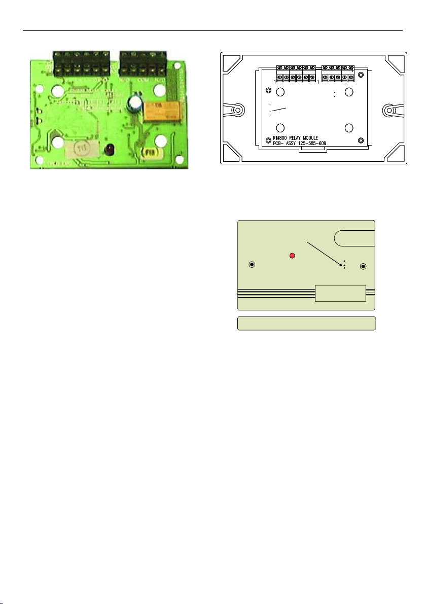
Fixing Instructions Doc. version 4.0 9/12
Fig. 1: Módulo entrada de contactos FC410CIM/
FC410RIM Modulo relè/ FC410RIM Relay Interface
Module/ FC Ausgangselement, nicht überwacht -
FC410RIM
Fig. 2: FC410RIM instalado en la cubierta/ FC410RIM
fissata al coperchio/ FC410RIM fitted to cover/
FC410RIM ins Gehäuse eingebaut
Fig. 3: FC410RIM instalado en la cubierta/ FC410RIM
Placca/ Facia Plate/ Kurzschlussisolator Vorderseite
L+ L- L+ L- 0+ 0- N/O C N/C
TB2
TB1
Puerto de programación
Porta di programmazione
Programming port
Programmieranschluss
Puerto de programación
Porta di programmazione
Address setting port
Programmieranschluss
Instrucciones de montaje Doc. versión 4.0
10/12 Fixing Instructions Doc. version 4.0
FC410RIM FireClass
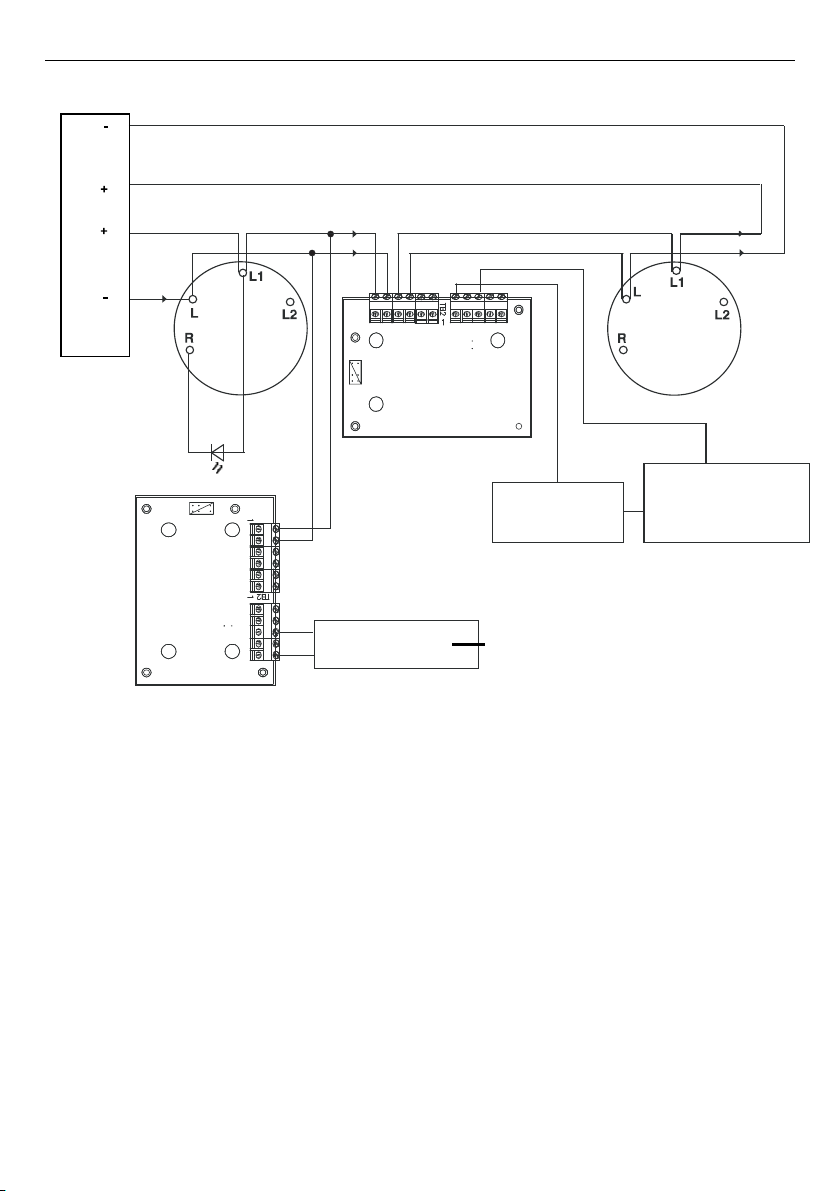
Fig. 4: Esquema de conexiones simplificado del FC410RIM/ FC410RIM Schema di collegamento/ FC410RIM
Simplified Wiring Diagram/ Typische Verdrahtung des FC410RIM
L1
L1
L1
L+ L- L+ L- O+ O- N/O C N/C
-O+O-
L
+L-L+L C/NCO/N
P1
P1
L1
Circuito de conmutación electrónico
Circuito elettronico switching
Electronic switching circuit
Schaltbare baugruppe
Fuente de
alimentación
Alimentatore
Power supply unit
Energieversorgung
Dispositivo externo/circuito
conmutable
Dispositivo esterno/
circuito commutabile
External device/
switchable circuit
Ein-und ausschaltbarer
verbraucher
Right
Left
Central de control
Centrale FC
FC controller
FC zentrale
Instrucciones de montaje Doc. versión 4.0

FireClass FC410RIM
Fixing Instructions Doc. version 4.0 11/12
Instrucciones de montaje Doc. versión 4.0

120.415.969_ISTISBL3FC410RIM, Doc. version 4.0, 29. May 2020
© 2020 Johnson Controls. All rights reserved. All specifications and other
information shown were current as of document revision date and are subject to
change without notice.
www.fireclass.net
Tyco Fire & Security GmbH, Victor von Bruns-Strasse 21, 8212 Neuhausen am
Rheinfall, Switzerland
FC410RIM FireClass
Other manuals for FC410RIM
1
Table of contents
Languages:
Popular Recording Equipment manuals by other brands


Patton electronics
Patton electronics SmartNode 4650 datasheet

Ferrari electronic
Ferrari electronic OfficeMaster CallRecording USB 1xBRI Quick start manual

Hameg
Hameg IEEE-488 FITTING INSTRUCTION

Music Thing Modular
Music Thing Modular SimpleEQ Build documentation

Toshiba
Toshiba G1IF4 instruction manual

TAMURA
TAMURA TU-6440 instruction manual