© Copyright 2003 by Fred Ginsburg. All Rights Reserved.
Page 6
Education & Training Division
EQUIPMENT EMPORIUM INC
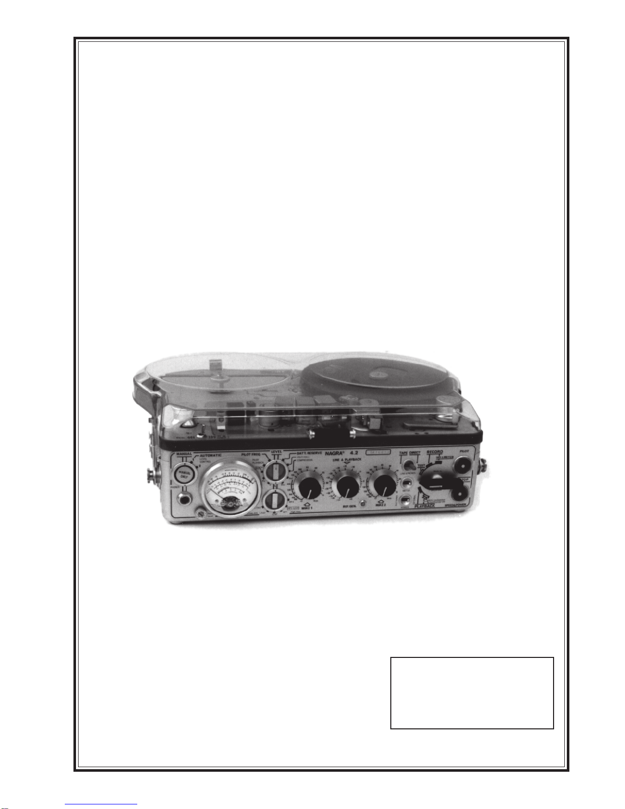
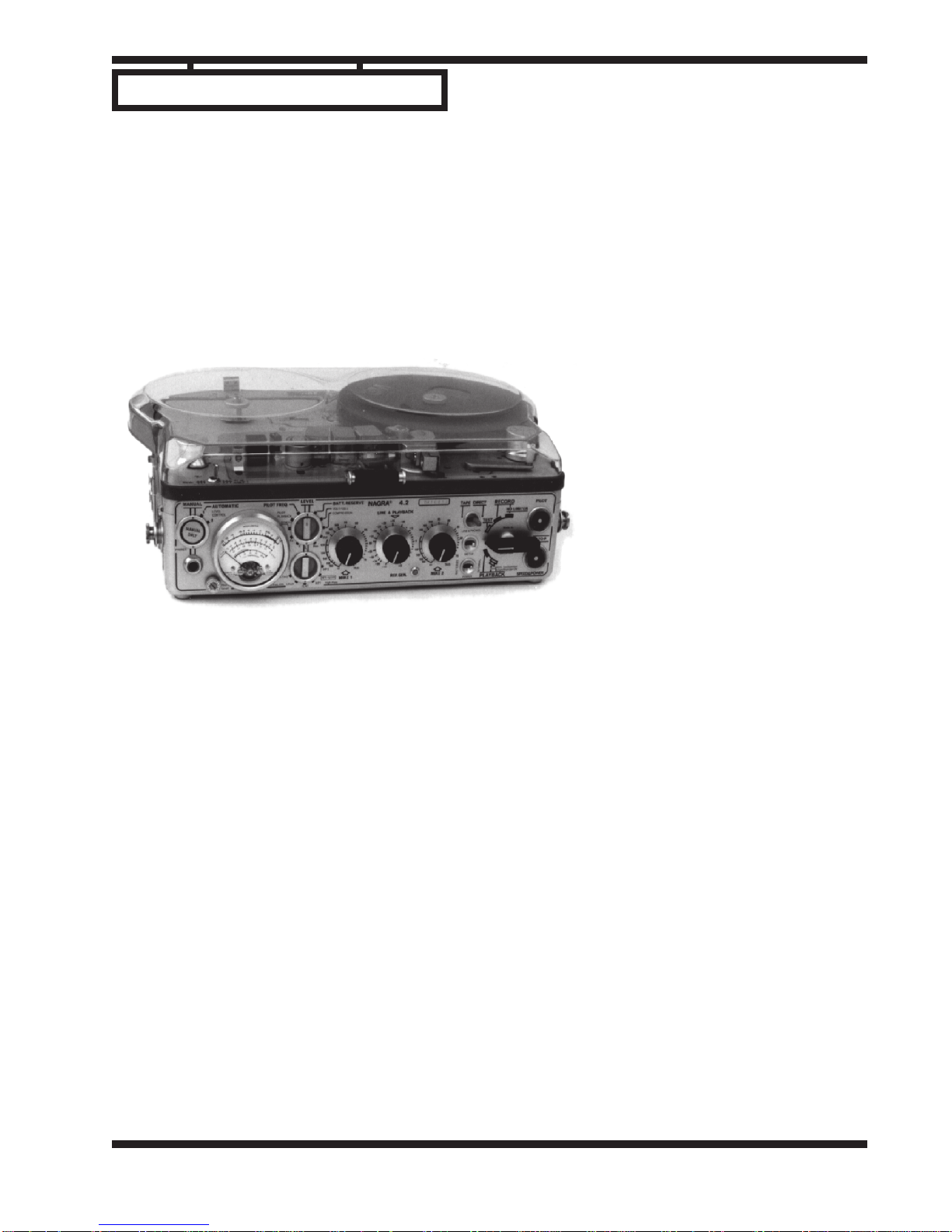
Guide to the Nagra 4.2 and
Production Sound Recording
Sync between the film camera and the tape recorder was achieved by a system known as neopilotone.
Again, both the camera and the sound recorder took advantage of the 60 Hz frequency provided by running
off of common AC electrical current.
But since the Nagra did not utilize sprocketed tape, it had to rely upon neopilotone to achieve sync. The
way the system works is that a 60 Hz sync pulse (in actuality a sine wave) is recorded onto the center of the
audiotape. When the recording is later played back for transfer, a special device known as a resolver com-
pares the sync frequency (sync pulses) on the tape against an external reference (another 60 Hz signal). The
resolver speeds up or slows down the tape speed so that both 60 Hz signals match up. The resolving process
compensates for errors such as tape stretch, slippage, and minor motor fluctuations.
We do not normally hear the 60 Hz sync pulse (hum) on the Nagra tapes because a second 60 Hz sine
wave is simultaneously recorded onto the tape. This second sync pulse is a mirror image twin (180 degrees
out of phase) of the first sync pulse. When the two sync pulses are played back over the head together, they
cancel each other out.
That is why you will hear the sync pulse if you play back a full track Nagra tape on a quarter-track or
half-track recorder.
If you attempt to razor blade edit a tape recorded with a Nagra, you will hear noise at the edit points
when you make a diagonal splice, since the diagonal cut eliminates part of the mirror sync pulse that other-
wise functions to cancel out the primary sync pulse. When using a Nagra for non-sync recording, such as
radio interviews, merely remove the crystal jumper plug from the right side of the machine to prevent a
sync pulse from being recorded that might interfere with any future (razor blade) editing.
It is very important to realize that Nagras do not run at 24, 25, nor 30 frames per second! They run at 7
1/2 INCHES per second. It is the FILM CAMERA that runs at frames per second, and then later it is the
MAG FILM RECORDER that will record at frames per second to match the film camera. But as far as the
Nagra is concerned, there are NO FRAMES per second, only inches per second IN REAL TIME.
What this means is that the crystal sync pulse system is intended to replicate or reproduce a recorded
event in precise real time — no longer and no shorter than the actual elapsed time.
If we were to film a scene that ran 10.00 seconds with a crystal controlled film camera running at 24 fps,
and then projected that same strip of film at 24 fps, we would re-create an event of 10.00 seconds duration.
During the same production, if we were to record audio of that 10.00 second event, we would require
that the audio recorder be able to play back that sound in precisely 10.00 seconds. Any longer or shorter —
due to tape stretch, slippage, or motor variation — would result in a loss of lip sync.
The Nagra is capable of reproducing those 10.00 seconds by means of recording a sync pulse (generated
by a crystal clock) onto the original tape, and then comparing (resolving) that sync pulse to a reference sync
pulse (such as that same crystal clock). The tape speed is minutely adjusted so that the sync pulses match up.
The end result is an audio event of 10.00 seconds. Real-time.
So where do the frames come in? At the same time that the Nagra plays back the audio in real time, a
sprocketed MAG FILM recorder is running at the same frame rate as the camera originally did. The audio
(10.00 seconds) is recorded onto a film strip with sprocket holes that is running at frames per second.
Question: If the Nagra is running at crystal controlled real-time, what is governing the speed of the mag
recorder during the transfer?
Some mag recorders are crystal controlled, but many of them take their speed control by the 60 Hz
frequency generated by our AC electrical system. Since the mag recorder and film projector are both referenc-
ing the same AC frequency, any variations in that frequency that may occur in the power line affect both
machines the same, so lip sync is maintained. When audio is transferred from a crystal Nagra to a mag
recorder locked to AC, we use a special AC power adapter (called the ATN) to both power the Nagra and to
provide an external sync pulse reference taken from the AC line. This external reference locks the Nagra to