INTRODUCTION
ELAN’s VEHP is an electronic 12 step stereo volume control with a FIXED
impedance of 1X designed specifically for use with amplifiers with power
outputs up to 100 watts. The VEHP features an IR receiver which passes IR
data to other sources as well as accepting IR information from the included
remote control or other IR devices. The VEHP also features an IR input so
that external controllers (keypads, VIA!®s, etc.) can be hard wired to this
device without using an IR emitter. Additionally, the VEHP features ELAN’s
patented Page/Doorbell Override to work with ELAN communication equip-
ment. This volume control should NOT be used in applications where imped-
ance-matching is necessary: use the VSE Electronic Stereo Volume Control
in these applications.
FEATURES
High-Power Capabiiity: Handles up to 100 Watts RMS
Override: Allows Page/Doorbell signals to override the music at a preset
level even with volume turned all the way down or with the VEHP in mute.
IR In/Out: A built-in IR receiver allows the VEHP to be controlled from the
included remote control, universal remote, keypad, VIA! Touch Screen, or
outboard IR receiver. IR can be sent to the VEHP using an IR emitter or
through the RJ45 jack on the rear of the unit. IR can be sent from the IR
output to source equipment, IR distribution networks or whole-house con-
trollers.
SENSE: Detects absence or presence of voltage. When voltage is absent,
the VEHP goes into Mute. The presence of voltage DOES NOT un-mute the
VEHP, however. A physical button press is required to un-Mute this device.
This allows the system or zone to be turned on without all of the VEHPs in
the system playing audio. Each VEHP will turn on when the zone or system
turns on, but they will all be in Mute. When connecting to ELAN S or HD sys-
tems, the SENSE feature can be used for either Zone-specific or System-
wide detection. ELAN Z systems provide System On/Off detection only.
ROUGH-IN
The VEHP fits into most 18 cu. in. rough-in boxes and P-rings. P-rings allow
the best access and depth and should be used where local building codes
allow. DO NOT install the VEHP in the same electrical box as high-voltage
(110VAC) devices such as dimmers, light switches, etc. as these devices will
cause harmful interference and create buzzing, humming, or other audio
interference. Close proximity to high-voltage devices can also cause unde-
sired IR operation.
Like any IR device, the VEHP’s IR receiver is susceptible to interference from
ambient light, sunlight, or plasma television radiation. Please do not mount
the unit in locations susceptible to these conditions.
NOTE: The VEHP is not warranted for outdoor installation.
WIRING
Speaker wire and CAT5 cable should be run from the main equipment loca-
tion where the system’s amplifier is located to the mounting location for
each VEHP. The speaker terminals on this unit will accommodate 14 to 24
AWG stranded copper speaker wire. Runs that exceed 150 feet should use
heavier gauge wire, but 16 or 18 AWG is usually sufficient. Check local
building codes for specific guidelines regarding in-wall wire runs. CAT5
cable is required when installing this unit to provide Power, Override, Sense,
IR In, and IR Out. This unit must be connected to power in order to function.
CONNECTIONS
RJ45 CONNECTIONS
1. Use ELAN C45P pre-terminated RJ45 cables or crimp your own
using the ELAN standard color code and pin-out.
2. Consult the following diagrams for specific CAT5 wiring requirements
for stand-alone or ELAN system operation.
3. Once proper connections are made at the head-end, plug the RJ45
connector into the jack on the rear of the VEHP.
4. Install the unit in the wall using the provided screws. Be careful
not to place tension on the CAT5 cable.
5. Test and adjust.
SPEAKER CONNECTIONS
1. Verify that the amplifier is powered down. Do not connect the RJ45
conector of the VEHP at this point.
2. Strip back 1/4” of the insulation from each conductor of the speaker
wire. Twist and verifythat there are no frayed ends.
3. Remove the AMPLIFIER and SPEAKER connectors from the volume
control. Connect the L+, L-, R+, R- conductors from the amplifier to
the appropriate terminal on the AMPLIFIER connector. Make sure to
maintain proper +/- polarity!
4. Connect the wires from the speakers to the appropriate terminals on the
SPEAKER connetor, again ensuring proper +/- polarity.
5. Replace the AMPLIFIER and SPEAKER connectors. DO NOT reverse
AMPLIFIER and SPEAKER CONNECTORS!!!!!!
DESIGN/CONFIGURATION
STAND-ALONE CONFIGURATION
The VEHP can be used in stand-alone configuations without using an ELAN
whole-house controller. Each stand-alone scenario will be slightly different,
but all will connect the same way as the following diagram explains.
The basic connections for stand-alone systems are as fol-
lows:
1. Amplifier Input-- Speaker wires from the amplifier (L+/-, R+/-)
2. Speaker Output--Speaker wires to speakers (L+/-, R+/-)
3. Power-- +12 Volts DC & Ground (RJ45 +12VDC=Gr/Wh,GND=Br)
4. IR-- IR Output and Ground (RJ45 IR=Wh/Bl, GND=Br)
ELAN SYSTEM CONFIGURATIONS
The VEHP is ideally suited for many ELAN whole-house audio distribution
applications. Features such as Volume Control Override, SENSE, and the
built-in IR receiver allow this unit to seamlessly integrate into the most basic
or most complex ELAN systems that the installer can imagine. Following are
diagrams showing typical applications using the VEHP in ELAN S, Z, and HD
system designs.
NOTE:Zones vs. Sub-Zones
A “Zone” is defined as an area of a whole-house audio system that has sep-
arate source control/selection capabilities.
A “Sub-zone” is a room or area that shares source selection/control with
another area, but typically has separate ability to control volume for the sub-
zone.
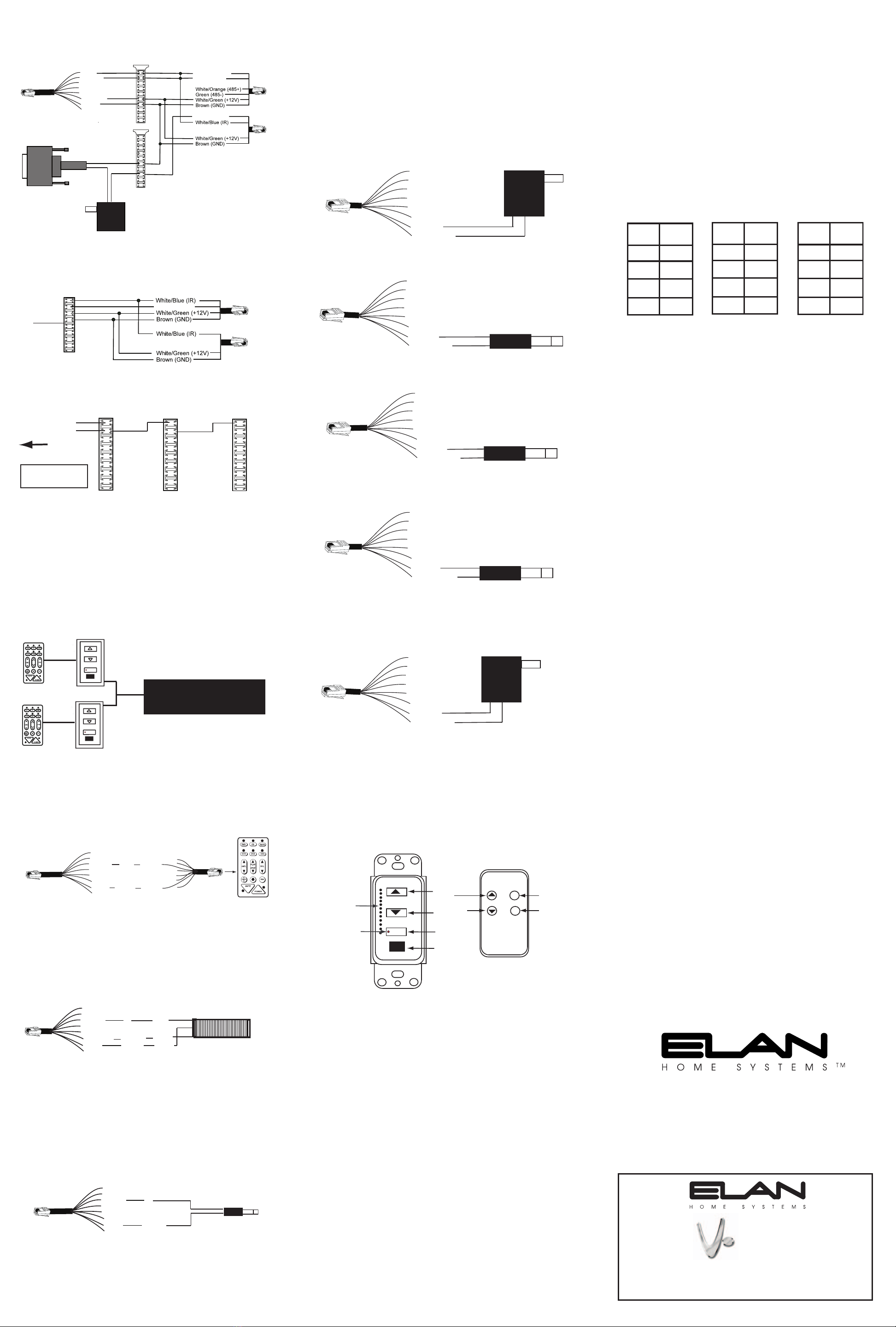
ELAN S6 SYSTEM DIAGRAM
ELAN S6 SYSTEM CONNECTIONS W/ Z600 AND VEHP
Using Internal Power of Z600 for Override
ELAN S6 SYSTEM CONNECTIONS W/ Z600 AND VEHP
Using an External Power Supply for Override