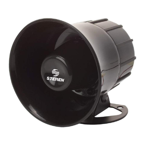
FireClass FC430LPBSB User manual

FIRECLASS Fire Detection System EN54-23 Open Class—FC430LPBSB LP Loop Powered Beacon-Sounder Base
Product Information Doc. Version 2 1/14
EN54-23 Open Class—FC430LPBSB LP Loop
Powered Beacon-Sounder Base
Introduction
The EN54-23 Open Class—FC430LPBSB LP Loop Pow-
ered Beacon-Sounder Base is designed to be driven
from a FIRECLASS controller via the addressable loop.
The FC430LPBSB LP is designed to be fitted between
a detector and a 4" mounting flange.
A ‘Type A’ mounting flange is supplied with the base
and can be fixed to a flat surface or a suitable electrical
backbox with standard 50 mm, or 70 mm fixing centres.
Alternatively, a DAB3-4 mounting flange (to be ordered
separately, refer to “Order Information” on page 14)
can be used with surface mount trunking.
Fig. 1 shows a general view of the base.
The beacon-sounder base may be used without a detec-
tor by fitting a blanking cap (see “Order Information” on
page 14).
The detector or blanking cap must be locked onto the
beacon-sounder base by using a locking device (sup-
plied).
The sounder has four volume settings:
High (90 dB ±3),
Mid High (80 dB ±3),
Mid Low (70 dB ±3) and
Low (60 dB ±3).
The beacon emits a white flashing light and has two
flash rates:
Slow Flash (½ Hz), or
Fast Flash (1 Hz).
The FC430LPBSB LP Beacon-Sounder Base devices are
synchronised, but not synchronous with other sounders
(FC430SB/FC410SNM) and beacons (FC430SAB).
The first flash of the beacon is synchronised with the
start of the tone.
The FC430LPBSB LP Beacon-Sounder Base has a built
in two port isolator.
The FC430LPBSB LP Beacon-Sounder Base requires
two addresses, not including the associated detector.
Fig. 1: General View of EN54-23 Open Class—FC430LPBSB LP Beacon-Sounder Base
LOCKING DEVICE
FITS HERE
PROGRAMMING
PORT

2/14 Product Information Doc. Version 2
Technical Specification FIRECLASS Fire Detection System
Technical Specification
Mechanical Characteristics
The overall dimensions are shown in Fig. 2. All dimen-
sions are in mm.
.
Fig. 2: FC430LPBSB LP Beacon-Sounder with Mounting Flange—Overall Dimensions
44
11
50
11
FC430LPBSB LP WITH TYPE ‘A’ MOUNTING FLANGE
FC430LPBSB LP WITH DAB3-4 MOUNTING
Fig. 3: Mounting Flange—Fixing Dimensions
50
80
70
60
Mounting Beacon-Sounder
The beacon-sounder body clips onto the
mounting flange.

FIRECLASS Fire Detection System Technical Specification
Product Information Doc. Version 2 3/14
Environmental Characteristics
Performance Characteristics
EMC:
The FC430LPBSB LP Beacon-Sounder Base complies
with the following:
Product family standard EN50130-4 in respect of:
– Conducted Disturbances,
– Radiated Immunity,
– Electrostatic Discharge,
– Fast Transients and
– Slow High Energy.
EN61000-6-3 for Emissions
Parameter Value
Weight:
Beacon-Sounder
Base
160 g
Materials:
Beacon-Sounder ABS/PC FR
Mounting Surface mount or conduit
mount
Table 1: Technical Specification
Parameter Value
Temperature:
Operating
Storage
-10C to +55C
-25C to +70C
Humidity Up to 95% RH
(non-condensing)
Pressure Sounder output is quoted for
atmospheric pressure of
1000 mBar.
Vibration Meets the requirements of
EN 54-3 and EN 54-23.
Shock Meets the requirements of
EN 54-3 and EN 54-23*.
Corrosion Passes the SO2corrosion test
from EN 54-3 and EN 54-23.
IP Rating IP21C (EN 60529)
Table 2: Environmental Characteristics
*—The DAB3-4 mounting flange was not incorporated within
the scope of the EN 54-23 approval.
Parameter Value
Sound
Performance
SPL at 90° at a
distance of 1m:
High:
Mid high:
Mid low:
Low:
Note:
EN54-3:2001 does
not test at 90°.
90 dB±3
80 dB±3
70 dB±3
60 dB±3
Light
Performance:
Light colour:
Flash rate:
EN54-23 Category O:
White flashing light
Fast Flash 1 Hz, or
Slow Flash ½ Hz
Table 3: Performance Characteristics

4/14 Product Information Doc. Version 2
Technical Specification FIRECLASS Fire Detection System
Electrical Characteristics Alarm Current
Sounder Tones
Table 6 details the tones available for selection in FIRE-
CLASS Express.
Approved Tones
The tones shown in Table 6 are approved at volumes
‘High’, ‘Mid-high’ and ‘Mid-low’ to EN54-3 with the
exception of the Alternating (NF-S 32.001) tone, which
is only approved at volumes ‘High’ and ‘Mid-High’. The
approved tones meet the specification as shown in
Tables 7 to 21. The data applies to both horizontal and
vertical planes.
Parameter Value
Addressable Loop Voltage 20 - 40 Vdc
DC Loop Loading:
Quiescent
Alarm
350 A
See Table 5: “Alarm
Current”
Isolator:
Maximum Loop Voltage 40 Vdc
Minimum Loop Voltage 20 Vdc
Maximum Rated Continuous
Current (Isolator Closed)
2 A
Maximum Rated Switching
Current (s/c)
2 A
Maximum Leakage Current
(Isolator Open)
6 mA into zone
(10 mA into Isolator)
Maximum Series Impedance
(Isolator Closed)
0.25
Isolator Switching Threshold
(Isolator Closed to Open)
20 V or below
Isolator Switching Threshold
(Isolator Open to Closed):
2.9 V to 3.5 V from
s/c
Table 4: Electrical Characteristics
Parameter Low/
Mid-Low
Mid-High/
High
Unit
Sound Output 60/70 80/90 dB
Sounder Only 2.55 4.5 mA
Sounder and
Beacon 0.5 Hz
8.2 10 mA
Sounder and
Beacon 1 Hz
9.35 11.3 mA
Table 5: Alarm Current
NOTICE: Bell Tone
This is a simulated bell tone with a limited
bandwidth. It is not advisable to mix
conventional bells and electronic sounders
producing a simulated bell tone.

FIRECLASS Fire Detection System Technical Specification
Product Information Doc. Version 2 5/14
Device
Mode
Name Tone Description
Monitored
No pulsing in
FIRECLASS
Express
Monitored with
Pulse Pattern
Assigned in
FIRECLASS
Express
Pattern Frequency
(Hz)
Rate 60/
70db
80/
90db
60/
70db
80/
90db
1 Dutch Slow
Whoop
Sweep 500 to 1200 500 Hz rising to
1200 Hz over 3.5 s
silence 0.5s repeat
No Yes No No
2 7 Hz Fast
Sweep
Sweep 800 to 970 0.1428 s ramp @
7 Hz
No Yes No No
3BS1Hz
Sweep
Sweep 800 to 970 1 Hz No Yes No No
4 2 Tone Alternating 660 / 880 500 ms per tone No Yes No No
5 Temporal 4 Intermittent 880 500 ms on
500 ms off x 4
followed by 1.5 s
silence
No Yes No No
6 Australian
Sound
(AS 1670.4)
(Temporal 3
type tone)
Intermittent
+ Sweep
500 to 1200 500 ms on
500 ms off x 3
followed by 1.5 s
silence, sweep
during on periods
No Yes No No
7 March Time
Beep
Intermittent 880 500 ms on
500 ms off
No Yes No No
8 Continuous Continuous 970 Steady No Yes No Yes
9 DIN 1 Hz
Sweep
Sweep 1200 to 500 1200 Hz falling to
500 Hz over 1 s and
repeat
No Yes No No
10 Banshee LF
Buzzer
Sweep 800 to 950 120 Hz No Yes No No
11 3 Hz
Banshee Fast
Sweep
Sweep 800 to 950 3 Hz No Yes No No
12 9 Hz
Banshee Fast
Sweep
Sweep 800 to 950 9 Hz No Yes No No
13 Alternating
(NF-S 32.001)
Alternating 554 / 440 554 Hz for 100 ms
and 440 Hz for
400 ms
No Yes No No
14 Yodalarm Alternating 800 / 1000 250 ms for each
frequency
No Yes No No
15 Conventional
Bell (Refer to
notice below)
continuous 1450 As per Banshee
Multi-Tone (MT)
Sounder,
Tone No. 32
No Yes No Yes
Table 6: Sounder Tones

6/14 Product Information Doc. Version 2
Technical Specification FIRECLASS Fire Detection System
Angle High Volume dB(A) Mid-High Volume dB(A) Mid_Low Volume dB(A)
40V 20V 40V 20V 40V 20V
15° 84.3 84.2 77.6 74.4 67.8 67.2
45° 82.7 82.1 76.5 75.5 66.6 65.1
75° 91.3 90.2 83.3 82.1 73.1 72.6
105° 89.1 87.7 79.8 78.7 69.0 68.2
135° 86.6 85.5 78.2 77.0 67.4 66.9
165° 88.6 87.4 80.2 79.1 69.6 69.0
Table 7: Dutch Slow Whoop Volume
Angle High Volume dB(A) Mid-High Volume dB(A) Mid_Low Volume dB(A)
40V 20V 40V 20V 40V 20V
15° 83.7 82.2 75.0 74.7 65.9 64.4
45° 82.3 82.1 73.8 73.2 63.5 65.4
75° 91.0 89.6 82.5 81.7 72.2 71.8
105° 87.6 86.6 78.8 78.3 68.1 67.8
135° 84.6 83.0 76.3 75.5 65.7 65.4
165° 86.9 85.5 78.4 77.6 67.9 67.6
Table 8: 7Hz Fast Sweep Volume
Angle High Volume dB(A) Mid-High Volume dB(A) Mid_Low Volume dB(A)
40V 20V 40V 20V 40V 20V
15° 84.3 82.6 76.4 74.8 66.0 65.4
45° 81.2 79.3 75.6 74.4 65.4 65.6
75° 90.4 89.0 83.3 81.8 73.1 72.3
105° 87.8 86.2 78.9 77.8 68.6 67.5
135° 84.8 83.4 76.7 75.7 65.8 65.6
165° 87.4 85.9 79.4 78.1 68.2 67.7
Table 9: BS 1Hz Sweep Volume
Angle High Volume dB(A) Mid-High Volume dB(A) Mid_Low Volume dB(A)
40V 20V 40V 20V 40V 20V
15° 83.0 81.5 74.6 73.8 63.5 63.1
45° 80.8 79.5 75.5 74.7 63.2 63.8
75° 89.4 85.5 82.0 81.5 71.9 70.8
105° 85.6 84.3 78.7 77.8 67.7 67.3
135° 85.2 83.8 77.2 77.0 66.6 66.2
165° 85.4 84.3 78.0 77.5 67.4 66.4
Table 10: 2 Tone Volume

FIRECLASS Fire Detection System Technical Specification
Product Information Doc. Version 2 7/14
Angle High Volume dB(A) Mid-High Volume dB(A) Mid_Low Volume dB(A)
40V 20V 40V 20V 40V 20V
15° 82.9 81.5 74.2 73.8 63.5 63.4
45° 80.9 80.1 73.8 74.0 64.2 63.9
75° 89.2 87.9 81.8 81.2 71.8 71.1
105° 85.6 84.5 78.7 77.8 67.5 67.4
135° 85.1 83.4 77.5 76.5 66.5 66.0
165° 85.5 84.0 78.1 77.3 66.9 66.6
Table 11: Temporal 4 Volume
Angle High Volume dB(A) Mid-High Volume dB(A) Mid_Low Volume dB(A)
40V 20V 40V 20V 40V 20V
15° 82.8 81.4 75.4 74.9 65.7 64.9
45° 80.7 79.2 73.8 72.7 64.1 64.5
75° 89.6 88.3 81.8 81.0 71.9 71.1
105° 86.5 84.9 78.2 77.3 67.3 66.4
135° 83.6 82.1 76.2 75.4 66.1 65.4
165° 85.9 84.5 78.0 77.1 67.9 67.2
Table 12: Australian (AS 1670.4) (Temporal 3 Type) Volume
Angle High Volume dB(A) Mid-High Volume dB(A) Mid_Low Volume dB(A)
40V 20V 40V 20V 40V 20V
15° 82.1 80.2 74.4 73.8 63.6 63.3
45° 80.1 79.3 74.0 72.3 61.5 63.3
75° 88.8 87.8 82.0 81.3 71.0 70.6
105° 85.6 84.5 78.8 78.0 67.8 67.4
135° 85.5 83.8 76.8 77.1 66.9 66.5
165° 86.2 84.6 78.5 77.8 67.7 67.2
Table 13: March Time Beep Volume
Angle High Volume dB(A) Mid-High Volume dB(A) Mid_Low Volume dB(A)
40V 20V 40V 20V 40V 20V
15° 85.5 84.0 79.0 77.9 69.1 68.4
45° 80.4 78.7 73.7 72.0 62.6 63.0
75° 90.2 88.8 83.4 82.3 73.5 73.1
105° 83.7 83.2 77.8 76.8 67.3 67.9
135° 80.9 78.6 74.3 73.6 64.1 63.6
165° 82.0 80.6 76.0 75.0 65.8 65.6
Table 14: Continuous 970Hz Volume

8/14 Product Information Doc. Version 2
Technical Specification FIRECLASS Fire Detection System
Angle High Volume Mid-High Volume dB(A) Mid_Low Volume dB(A)
40V 20V 40V 20V 40V 20V
15° 82.9 81.4 76.4 75.3 66.2 65.9
45° 80.3 78.9 74.3 73.5 64.1 63.8
75° 89.6 88.2 82.4 81.3 72.1 71.8
105° 86.4 85.1 78.9 77.9 68.1 67.7
135° 83.7 82.2 76.9 75.9 66.1 65.7
165° 86.1 84.4 76.9 77.7 68.0 67.4
Table 15: DIN 1Hz Sweep Volume
Angle High Volume dB(A) Mid-High Volume dB(A) Mid_Low Volume dB(A)
40V 20V 40V 20V 40V 20V
15° 82.7 81.5 74.3 73.8 65.4 63.3
45° 80.1 79.5 73.6 72.4 61.9 61.6
75° 90.4 89.1 82.0 81.1 71.7 71.0
105° 87.5 86.4 79.0 78.0 69.5 67.3
135° 84.6 83.4 76.5 75.8 65.6 65.6
165° 86.5 85.5 78.6 77.7 67.7 67.1
Table 16: Banshee LF Buzzer Volume
Angle High Volume dB(A) Mid-High Volume dB(A) Mid_Low Volume dB(A)
40V 20V 40V 20V 40V 20V
15° 82.7 81.4 74.6 74.2 65.0 63.9
45° 81.3 79.9 75.4 75.3 62.5 62.4
75° 90.1 88.9 80.3 79.6 71.8 71.5
105° 87.2 85.9 78.8 78.8 68.6 68.2
135° 84.7 83.1 73.1 72.3 65.8 65.7
165° 86.9 85.3 76.8 76.0 67.9 67.5
Table 17: 3Hz Banshee Fast Sweep Volume
Angle High Volume dB(A) Mid-High Volume dB(A) Mid_Low Volume dB(A)
40V 20V 40V 20V 40V 20V
15° 82.4 81.6 74.2 73.6 65.0 64.7
45° 80.1 79.6 72.6 71.4 64.6 62.3
75° 90.1 89.2 82.0 80.8 71.4 71.3
105° 87.4 86.7 78.9 78.3 68.5 67.9
135° 84.4 83.4 76.4 75.9 66.2 65.4
165° 86.8 86.1 78.6 78.0 67.9 67.5
Table 18: 9Hz Banshee Fast Sweep Volume

FIRECLASS Fire Detection System Technical Specification
Product Information Doc. Version 2 9/14
Angle High Volume dB(A) Mid-High Volume dB(A)
40V 20V 40V 20V
15° 80.9 80.1 73.0 72.9
45° 82.1 79.6 73.4 72.7
75° 88.5 87.6 79.9 79.8
105° 85.7 84.7 76.5 76.7
135° 82.7 81.7 73.9 74.7
165° 83.7 83.0 75.3 75.4
Table 19: Alternating (NF-S 32.001) Volume
Angle High Volume dB(A) Mid-High Volume dB(A) Mid_Low Volume dB(A)
40V 20V 40V 20V 40V 20V
15° 83.9 82.5 79.0 77.7 68.6 68.2
45° 81.0 78.8 76.1 74.4 65.5 65.1
75° 88.5 87.0 83.0 81.8 71.9 71.8
105° 85.6 84.1 78.1 76.6 66.2 65.7
135° 84.3 82.8 77.9 76.9 66.8 66.0
165° 85.1 83.3 79.5 78.2 68.6 68.2
Table 20: Yodalarm Volume
Angle High Volume dB(A) Mid-High Volume dB(A) Mid_Low Volume dB(A)
40V 20V 40V 20V 40V 20V
15° 85.4 85.2 78.2 78.6 68.2 67.8
45° 81.0 78.5 76.5 76.7 62.5 62.0
75° 91.0 89.8 81.6 81.9 74.0 73.6
105° 84.8 84.0 74.6 75.2 66.7 68.5
135° 78.0 76.7 77.9 78.4 61.0 61.3
165° 80.7 79.0 78.8 78.3 63.3 62.8
Table 21: Conventional Bell Volume

10/14 Product Information Doc. Version 2
Technical Specification FIRECLASS Fire Detection System
Beacon Information
Category O - open class device (See Table 22 and
Fig. 4). The data applies to both the Slow Flash (1/2 Hz)
and the Fast Flash (1 Hz) while it is fitted with either a
detector or a blanking cap.
The light distribution is cylindrically symmetrical about
an axis at a right angle (Alpha of 90°) to the surface on
which the device is mounted, i.e. when the device is
mounted on a horizontal ceiling, the light distribution is
symmetrical about an axis extending vertically down-
wards through the centre of the device. The light distri-
bution in Fig. 4 represents a cross-section through the
volumetric shape using the values as indicated in
Table 22.
Alpha
[degrees]
Distance
[metres]
90 0
75 0
60 1
45 1.4
30 1.75
15 1.95
01.85
Table 22: FC430LPBSB LP Beacon-Sounder— 0.4 lm/m2
Illumination Distance
Fig. 4: FC430LPBSB LP Beacon-Sounder—Graphical Illustration of Ceiling Mount Light Distribution
0.5
011.5 2
0
90
o
o
DISTANCE [METRES]
LOCATION OF DEVICE
AXIS OFFF
SYMMETRY
ALPHA [DEGREES]

FIRECLASS Fire Detection System Technical Specification
Product Information Doc. Version 2 11/14
Address Programming
The factory set address is 255. The device should be
programmed with its loop address before installation
using an FC490ST with an ancillary lead that plugs in to
the device's programming port (see Fig. 1).
The FC430LPBSB LP Beacon-Sounder uses two con-
secutive addresses on the addressable loop, starting
from the chosen programmed address number. These
addresses are automatically generated when a
FC430LPBSB LP Beacon-Sounder Base is selected in
FIRECLASS Express.
The address configuration is as follows:
FC430LPBSB LP Beacon-Sounder Base
Configuration
Sounder tone (Device Mode), sounder volume output
(Sensitivity) and beacon flash rate (Device Mode) are
configured in FIRECLASS Express.
Bell Mapping
If it is required for the sounder to operate as a Bell Map
output, then the Group to which the device belongs
must be put into the Bell Map Outputs Supergroup.
To achieve this, select group 50 Bell Map Output SG
and then select “Edit Members”. Use “Add member”
to include the Points group into the Bell Map Output SG.
If the sounder base needs including in any sounder
Walk Test, then super group number 51 “Sounders to
walktest SG”, will have to be edited to add the point's
group to the list of supergroup members.
For the beacon to be included as a visual output con-
trolled by the Bell Map, the points group needs to be
included in ‘Bell Map Visuals SG’, 58.
Output Pulse Pattern
Output pulse patterns are restricted such that the
period between a sounder Low to High transition to the
next Low to High transition is a multiple of the beacon
flash rate period.
Fault Monitoring
Both the beacon and sounder are monitored. The last 2
columns of Table 6, “Sounder Tones,” on page 5,
shows if the sounder is monitored, as a function of vol-
ume setting and system configuration. Sound monitor-
ing is also referred to as Reflective Sound Monitoring
(RSM). For further details on the application of this func-
tion, refer to the Technical Publications of the relevant
Control and Indicating equipment.
Isolator Operation
The built-in isolator serves as a protection device
against short circuits. It operates by isolating the sec-
tion of line containing the short circuit from devices on
the line and from the rest of the line (refer to Fig. 5).
Address Type
n Sounder Device
n+1 Beacon Device
Table 23: Address Configuration

12/14 Product Information Doc. Version 2
Technical Specification FIRECLASS Fire Detection System
Optimum operation requires the line to be wired as a
loop, so that a section of line with a short circuit can be
isolated between a pair of isolator devices (including
FC430LPBSB LP Beacon-Sounder Base).
In order to enable the isolator’s use in a looped circuit, it
is capable of passing current in both directions:
Loop IN to Loop OUT or
Loop OUT to Loop IN.
In the event of a line short circuit, the line isolator con-
tinues to power its Beacon-Sounder, providing that
either Loop IN or Loop OUT remains intact. When a
short circuit develops, the adjacent isolator devices will
isolate both sides of the loop from the faulty device/
cable.
The operation of the loop driver means that there are
effectively 2 operational modes for the built-in isolator.
When the loop is first powered, if a section of the
line appears as a low impedance (with an equivalent
resistance of <400), the isolator will restrict the
power to that section of line until the fault is cleared.
If a short circuit is introduced onto the line when the
loop is already powered up, in most instances the
controller’s internal protection will switch in before
the line isolator. The voltage is then removed from
the line by the controller, on restoration, the isolator
devices will isolate the low impedance section of the
line.
Fig. 5: Simplified Isolator Diagram
+VE +VE
-VE
FC430LPBSB
LP
MONITOR LOOP
OUT
LOOP
IN MONITOR
-VE

FIRECLASS Fire Detection System Cabling
Product Information Doc. Version 2 13/14
Cabling
Cables should be selected in accordance with local
standards. Cabling should be connected as shown in
Fig. 6 ensuring correct polarity.
Each terminal connection will accept wire size up to
2.5 mm2(MICC or similar).
Fig. 6: Simplified Wiring Diagram for FC430LPBSB LP Beacon-Sounder
L
L1
L2
R
L
L1
L2
R
L
L1
L2
R
L
L1
L2
R
L
L1
L2
+
-
M
M
+
-
M
M
M
DETECTOR
BASE (4B)
FC430LPBSB LP
FIRECLASS
CONTROLLER
DETECTOR
BASE (4B)
DETECTOR
ISOLATOR
BASE (4B-I)
DETECTOR
BASE (4B)

© FIRECLASS. Hillcrest Business Park, Dudley, West Midlands, DY2 9AP, UK
www.fireclass.co.uk
FC-D-LPBSOC-PI, doc. version 2, 13. August 2014
Subject to change without notice.
CPR Information FIRECLASS Fire Detection System
CPR Information Order Information
Fig. 7: CPR Information
0832
DoP-2014-2009
14
516.800.973 FC430LPBSB LP
Fire alarm device – Sounder and Visual alarm device (VAD)
with short circuit isolator for use in fire detection and
fire alarm systems installed in and around buildings
Type A
Essential Characteristics
Performance under fire condition: Pass
Operational reliability: Pass
Durability:
Temperature resistance: Pass
Humidity resistance: Pass
Corrosion resistance: Pass
Shock and vibration resistance: Pass
Electrical stability: Pass
Resistance to ingress: Pass
EN54-17:2005
Performance under fire conditions: Pass
Operational reliability: Pass
Durability:
Temperature resistance: Pass
Vibration resistance: Pass
Humidity resistance: Pass
Corrosion resistance: Pass
Electrical stability: Pass
EN54-23: 2010
Duration of operation: Pass
Provision for external conductors: Pass
Flammability of materials: Pass
Enclosure protection: Pass
Access: Pass
Manufacturer's adjustments: Pass
On-site adjustment of behaviour: Pass
Requirements for software controlled devices: Pass
Coverage volume: Pass
Variation of light output: Pass
Minimum and maximum light intensity: Pass
Light colour: White
Light temporal pattern / frequency of flashing: Pass / 0.5Hz and 1Hz
Marking and data: Pass
Synchronization: Pass
Durability:
Temperature resistance: Pass
Humidity resistance: Pass
Shock and vibration resistance: Pass
Corrosion resistance: Pass
Electrical stability: Pass
EN54-3: 2001 + A1:2002 + A2:2006
Control Equipment Limited, Hillcrest Business Park, Cinderbank,
Dudley, West Midlands DY2 9AP. United Kingdom
Product Order Code
EN54-23—FC430LPBSB LP Loop
Powered Beacon-Sounder Base
516.800.973
DAB3-4 Mounting Flange (Conduit) 516.800.959
Sounder Blanking Cap 557.001.040
Table 24: Order Information
Table of contents
Other FireClass Security System manuals
