Carrier SYSTXCCSAN01 Instructions and recipes

SYSTXCCSAN0t
lnfinit S stem Access NoduMe
\isit "__ _.carrier.com Installation and Start-Up instructions
HEATUNG & COOLING
This is the safety°alert symbol z_ When you see this symbol on
the equipment and in the instruction manual, be alert to the
potential for personal i11.iuW [ nderstand the signal words DAN-
GER, _'_ARNING, and CA[ TION These words are used _ith
the sa_kty°alert symbol DANGER identifies the most serious
hazards, _hich will result in sexere personal in3uUor death.
_ARNING signifies a hazard, which could result in personal
iaju W or death (A[ TION is used to identK)- unsafe practices,
which ma? result in minor personal irwinW or product and property
damage. NOTE is used to highlight suggestions which will result
in enhanced installation, reliability, or operation.
INSTALLATION CONSIDERATIONS
Infinity System Access Module
SYSTXCCSAN01 A97040
NOTE: Read the entire instruction manual be%re starting the
installation
This symbol --> indicates a change since the last issue.
TABLE OF CONTENTS
SAFETY ( ONSIDERATIONS 1
INSTALLATION CONSIDERATIONS ....................................... 1
INTRODUCTION .................................... 1
INSTALLATION .......................................... ! ° 3
Check Equipment and Job Site ....................... 1
Component Location and Wiring (onsiderations ........ 2
Connect Power Source ........................... 2
Radio Test ...................................... 2
Install ( omponents .............................. 2
Connect Infinity Systems ......................... 2
Connect Water Sensor ........................... 2
System Start°E p ................................ 3
PIN Number ................................... 3
RS=232 ( onnector .................................... 3
Updating System Profile ................................ 3
Troubleshooting ...................................... 3
SAFETY CONSIDERATmONS
Improper installation, adjustment, alteration, service,maintenance,
or use can cause fiie, electrical shock, or other conditions that may
cause personal injury or property damage. Consult a qualified
installer, service agency, or your distributor or branch for infor=
marion or assistance. The qualified installer or agency must use
factory authorized kits or accessories when modifying this product.
RefEr to the individual instl_actions packaged with the kits or
accessories when installing. Follow all safety codes and wear
safety glasses. Have fire extinguisher available. Read these in=
structions thoroughly and [bllow all warnings or cautions attached
to the unit. Consult local and state building codes and Sheet Metal
and Air Conditioning National Association (SMACNA) %r special
installation requirements.
Before the actual installation of a System Access Module can
begin, determine the mounting location. A radio test must be
performed with the System Access Module in the intended
mounting location. See below on how to perform a radio test. The
System Access Module is powered with a 24 VA( transformer
(included). A 120VAC supply must be near the mounting location
of the System Access Module. Provisions must be made to secure
the transformer to the outlet. The D=wire (24 VAC) l_-om the
Infinity system MIST NOT be used to power the System Access
Module. Use this instruction to guide the actual installation process
after the Infinity system(s) have been installed. One System
Access Module is capable of handling two Infinity systems.
mNTRODUCTION
An Infinity System Access Module allows remote com_ectivity %r
up to two Infinity systems within the same building _he Infinity
system owner as well as authorized dealer can monitor and control
the system via the interact as well as by telephone. The System
Access Module communicates d_rough a two-way radio via the
Skytel paging network. Please visit:
http:iiwww.skvtel comicovera_eitelemetlw coverage htm to check
coverage for the installation site. The coverage must be listed as
"Full Service" for the System Access Modtde to _imction properly.
Please note that Skytel is continuously expanding their service area
so coverage may not be indicated by the web site. The System
Access Module can also monitor a &y=contact sensor to provide a
warning for the presence of water in the building, or some other
use. If the sensor is active, the Infini w system will not be disabled
or shut down.
mNSTALLATION
Step l--Check Equipment and Job Site
INSPE(T EQ[ IPMENT File claim with shipping company,
prior to installation, if shipment is damaged or incomplete
Manufacturer reserves the right to discontinue, or change at any time, specifications or designs without notice and without incurring obligations.
_2 PC 101 Printed in USA Catalog No. SAM01-1SI Pg 1 05-05 Replaces: NEW
a

Step 2--Component Location and Wiring Consider-
ations
ELECTRICAL SHOCK HAZARD
Failure to _bllow this warning could result in personal injury,
death, o1"possible equipment damage
Disconnect supply power before routing wire
NOTE: All wiring must comply with national, state, and local
codes
LOCAT]NG SYSTEM ACCESS MODULE
Since the System Access Mo&le (SAM) uses two=way radio,
choose a potential mounting location that is as high and as close to
outside walls or windows as possible to attempt to maximize radio
coverage The coverage is dependent on where the Sky-tel trans=
ceivers are tocated. It" one location does not work, try the opposite
side to get the device in closer directional proximity Temporarily
mount the System Access module in the intended pe*manent
mounting location until the radio test has passed 100%.
The System Access Module is approved for indoor use only and
should never be installed with any of its components exposed to
the elements. The System Access Module may be installed in any
area where the temperature remains between =4c>and 158°F and
there is no condensation The cover must be installed to prevent
damage from other sources Do not locate where it will be
accessible to chil&en. The SAM should be mounted in the vertical
position. Remember that wiring access and Skytet reception are the
most imporq_ant considerations
Select a location near the Infini w fm'nace or fan coil where wiring
fiom the User Inter_tce, each Remote Room Sensor or Smart
Sensor, each damper actuator, and the equipment itself can come
together easily.
ELECTRICAL OPERATION HAZARD
Failure to %llow this caution may result in equipment damage
or improper operation
To prevent possible damage to the System Access Modole, do
not mount on plenum, duct work, or flush against _/rnace.
WIRING CONSIDERATIONS Ordinary thermostat wire is
ideal when wiring the System Access Module (shielded cable is
not necessary) Use 22 AWG or larger _br normal wiring Lengths
over 100 _L should use 20 AWG or larger wire.
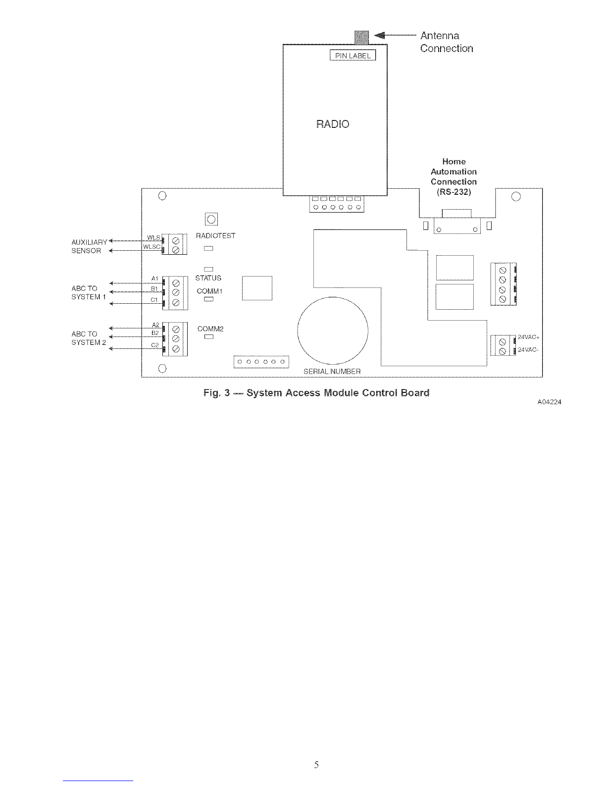
Step a--Connect Power Source and Antenna
Screw the antenna to the radio connector See Fig 3 for antenna
attachment location
A separate 24 VAC transfbrmer is included to power the System
Access Modute DO NOT connect the D-wire (24 VAC hot) fi'om
the Infinity system.
The trans_bm_er is heavy Make sure it is secured to the power
outlet with an appropriate screw through the boss on the tlans°
Step 4--Radio Test
The purpose of this test is to verify' effective 2-way commtmica=
lions at the installation site. The test must pass 100% before the
installation of the SAM can continue.
Press and hold the RADIO TEST button fbr at least 5 seconds.
A flashing Yellow LED will indicate the test is in progress. A
flashing Yellow and Green LED means the transmission is
complete and the System Access Module is waiting for a reply. A
constant Green LED means the radio test has passed. The radio
will per%tin three message tests, so this sequence will occur d_ree
times If the System Access Module has errors during the process,
the test could take up to 15 minutes
If the Red LED is tit solid, then the System Access Module _idled
to send the message. Try a new mounting location for the System
Access Module.
If the Yellow LED is tit solid, then the System Access Module sent
its message but did not receive a reply. The ( arrier server may be
down or the received signal is weak. Try a new mounting location
for the System Access Module.
Aborting Test - There is no method to abort a radio test once it is
started, other than to remove power.
The LEDs will maintain their state for 1 hour after the test.
Pressing the Radio Test button momentarily will clear the LEDs.
Pressing the Radio Test button again for five seconds will repeat
the radio test. See Fig. 2for a description of the radio test and LED
sequence.
Step 5-- Instal! Components
INSTALL SYSTEM ACCESS MOD[ LE Once the radio test
has passed, d_e System Access Module can be permanently
installed. The System Access Modnle is designed so that wires can
enter it t_-om behind, above, or below. Plan wire routing befbre
mounting.
1. Remove cover to access mounting holes.
2. Mount back plate to wall using screws and wall anchors
provided.
3. Level back plate and tighten screws.
Step 6-- Connect Bnfinity Systems
UNIT OPERATION HAZARD
Failure to follow this caution may result in improper unit
operation.
Improper wiring of the ABC connector will cause the System
Access Module to operate improperly. (heck to make sure all
wiring is correct befbre proceeding with installation or
mining on power.
Connect the A, B, and C wires fi'om the Infinity System to
terminals labeled AI, BI, and C1. Connect the second Infinity
System (if present) to the tem_inals labeled A2, B2, and (72
ABC bus wiring only requires a three wire connection; however, it
is good practice to ton thermostat cable greater than three wires in
the event of a damaged or broken wire during the installation.
It is recommended that the following color code be used when
wiring each ABC connector:
A Green Data A
B Yellow Data B
C White 24VAC (Corn)
NOTE: The D-wire (red - 24 VAC hot) fi'om the Infinity system
is not connected to the System Access Module.
It is not mandatory that the above color code be used, but each
ABC connector in the system MUST be wired consistently.
Step 7--Connect Auxiliary Sensor (optional)
The System Access Module will support a &y contact sensor for
use with water detection or some other use as seen fit. Connect one
side of the contacts to connector AUXC (common) and the other
side to connector AUX (input). The sensor input can provide up to
20mA at 5 volts d.c. If the sensor input is active, it will not shut
down or affect operation of the HVAC system(s). A pop=up
message will appear on the user interface indicating the auxiliary-

sensorisactive.Thehomeownerwillalsobenotifiedviae°mail
and/orphoneifsochosenontheintemetwebinterface.
Step8--SystemStart-Up
Afterasuccessf_/lradiotesthasoccun'ed,powermaybeappliedto
theInfinitySystem(s)The user interface of the Infinity System
will automatically find the System Access Module at power on.
System installation screens will automatically appear and will
display the Equipment Summary screen when finished. The
Equipment Summary screen will display REMOTE AC(ESS near
the bottom of the screen.
If REMOTE AfCESS is not displayed, check connections to fl_e
ABC wires as well as ensure the Yellow LED is tit on the System
Access Module (this ensures the module has power) The green
LED will be lit next to each AB( connection if the user interfi_ce
has established communication.
Step 9--PIN Number and Serial Number
The PIN' and Serial nm'nber of the System Access Module are used
by the system owner to register their system with Carrier Remove
the sticker containing the PIN number fiom the radio and install at
the fi'ont of the Owner's Guide. Also, write down the SAM serial
number in the Home Owner's Guide. The serial number can be
found on the SAM packaging, at the bottom of the large SAM
circuit board (see Fig. 3), or in the user inter_tce Service Menu. If
PIN number is lost or missing, it can be [bund by entering the
Service Menu of the User InterI:itce (10 second press of the
Advance button) and looking at the Model/Serial Numbers screen.
The PIN will be listed with the System Access Module model and
serial numbers.
RS-232 Connector
An RS=232 port has been provided %r connection to home
automation equipment. Consult your home automation supplier for
support
Updating System Profile
The Infinity System will automatically send system in%rmation to
Can'ier's computer servers within one hour after the system has
been successfillly installed. Access to the system via the internet or
telephone will not be available until this occurs. The system cart be
forced to send its infbm_ation through the following process if
intemet and telephone access is required immediately. Press and
hold the RADIO TEST button for 15 seconds. When the button is
first pressed, the red LED will turn on. Five seconds into the press,
the yellow LED will turn on. 15 seconds into the press, the green
COM1 LED will mm on. Release the button when the green LED
rams on. The red LED will flash when messages are being sent.
The red and yellow LEDs will flash when the SAM is waiting for
message replies. Upon successfi/l profiling, both green LEDs will
be lit. If profiling is not successful, the red LED will be lit solid.
The entire profiling process can take up to 15 minutes per Infinity
System. If two systems are connected to one SAM, then the
profiling process can take up to 30 minutes.
If the Infinity system AB( wiring is moved from connector 1 to
connector 2(or vice versa), or Infinity equipment has changed, the
System Access Module must update Can'ier's servers with the new
in%relation. This will happen automatically within one hour, or
can be manually forced with the process described above.
TROUBLESHOOTING
FAULT INDICATORS Under normal operation, the Yellow
and Green LED will be on continuously (solid). If the System
Access Module does not receive communications with the Infinity
system, the Green LED will not be on. If there are faults present,
the Yellow LED indicator will blink a two digit status code. The
first digit wilt blink at a fast rate, the second at a slow rate.
STATUS CODE DESCRIPTION
45 Board Failure
61 Radio out of range (no coverage for five minutes)
62 Loss of communication with the radio
Radio not registered with the local network
63 (unregistered for five minutes)
64 Auxiliary sensor active

Green "fellow Red
Flash Yellow at 1Hz O "_ O
Flash Yellow at 1Hz
and solid Red
Green "fellow Red
Wait for Reply Flash Green andYellow
(short) at 1 Hz
Flash Green and Yellow at
1Hz and solid Red
ISend Message 2 Flash Yellow 2 times,
(short) 1 second off
Green Yellow Red
Green Yellow Red
Green Yellow Red
Flash Yellow 2 times
and solid Red
Green Yellow Red
Flash Green andYellow Green Yellow Red
Wait for Reply _ ._
(long) 2 times O
2 times and solid Red
ISend Message 2] Flash Yellow 3 times
(long) 1 second off
Green Yellow Red
Green Yellow Red
o o
Flash Yellow 3 times
arid solid Red
Green Yellow Red
Green Yellow RedWait for Reply Glash Green and Yellow ._ j_
(long) 3 times O
Glash Green and Yellow
3 times and solid Red
Green Yellow Red
Green Yellow Red
All tests passed Solid Green LED _.
Yellow and Red off O O
_r_
Fig. 2 -- Radio Test Process and LED Sequence A05073

AUXILIARY <
SENSOR *<
ABC TO
SYSTEM 1 <
<
ABC TO <
SYSTEM 2 <
WLS_ RADIOTESTJVLSC EZD
DZ]
STATUS
COMM1
DD
COMM2
EZ3
PIN LABEL ]
RADIO
_ Antenna
Connection
Home
Automation
Connection
--I (RS-232)
F-..............]
S-to ooD
0 O0 O00] SERIAL NUMBER
Fig. 3 -- System Access Module Control Board
©
A04224

Copyright 2005 CARRIER Corp., 7310 W. Morris St • Indianapolis, IN 46231 SAM01 lsi
Manufacturer reserves the right to discontinue, or change at any time, specifications or designs without notice and without incurring obligations,
Book 1 4
Tab 10a 12a PC 101 Printed in USA. Catalog No. SAM01-1SI Pg 6 05-05 Replaces: NEW
Other Carrier Security System manuals
Popular Security System manuals by other brands

Bentel Security
Bentel Security Wave/WSB quick start guide

Milanity
Milanity Milan Vortex SLEN01 user manual

Amico
Amico Alert-3 LCD v2.3 operating & maintenance manual

GSI Electronics
GSI Electronics Agri-Alert 800EZe user manual

Arlec
Arlec AM 500 Installation & operating instructions

Carlos Silva
Carlos Silva SAR plusCOM installation guide