Fireco ROOF BASE User manual
ROOF
MOUNTED
TELESCOPIC MASTS
USER GUIDE AND
MAINTENANCE
INSTRUCTIONS

USE AND MAINTENANCE FOR ROOF MASTS
SAFETY WARNINGS
GUIDE TO ROOF-MOUNTED MODELS
VEHICLE ROOF FITTING
INSTALLING A LAMP UNIT
INSIDE THE T&T (TILT & TURN) UNIT
ELECTRICAL WIRING
PNEUMATIC CONNECTION
REMOTE CONTROL
USE OF THE REMOTE CONTROL
TROUBLESHOOTING
ELECTRICAL WIRING DIAGRAMS
ROOF-MOUNTED TELESCOPIC MASTS
Fireco Roof-Mounted Masts are the ideal solu-
tion where compact roof mounted lighting sys-
tems are required.
The user has a choice of 3 types of remote con-
trol, all of which control all mast functions.
Control Options:
• Hard-Wired version with spiraled cable and
plug
• Radio controlled version (range approxi-
mately 30m)
• Smart type
Fireco’s Tilt & Turn head unit allows lighting,
cameras or sensors to be directed where re-
quired at any angle.
COPYRIGHT
All information and data in this document remains the property of:
Fireco Srl – Via E. Fermi, 56 – 25064 Gussago (BS) ITALY VAT n° 03208290175
Any unauthorised reproduction, total or partial, is prohibited.
4
5
6
10
11
12
13
14
17
18
20
INDEX
2 3

USE AND MAINTENANCE FOR ROOF MASTS
A few important suggestions to avoid more common accidents:
WARNINGS
ATTENTION !
Ensure that, during use and whilst the mast is being extended,
no obstructions or people are in the working area
Ensure the vehicle is completely stationary and that the hand-
brake is on
Check that the vehicle’s pneumatic and electrical supply
systems are compatible with the mast supplied
Make sure the mast is not equipped with non-certied devices
and that any attachments do not exceed the maximum
recommended mass and dimensions
•
•
•
•
VERSIONS AVAILABLE ROOF
ROOF BASE
ROOF M
ROOF PLUS
Aluminium frame
Ø 90-115 mm mast
Internal spiralled cable
Ø3.5 mm Tube Thickness
4,80m Maximum Mast extension
Built-in Compressor*
Wired, Radio or Smart remote controls
12/24V Supply Voltage
* available upon request with built-in compressor
Aluminium frame
Ø 90 mm mast
Internal spiralled cable
Ø3.5 mm Tube Thickness
2,56m Maximum Mast extension
Built-in Compressor*
Wired, Radio or Smart remote controls
12/24V Supply Voltage
* available upon request with built-in compressor
Aluminium frame, ABS cover
Ø 64-77 mm mast
Internal spiralled cable
Ø3.5 mm Tube Thickness
3,12m Maximum Mast extension
Built-in Compressor*
Wired, Radio or Smart remote controls
12/24V Supply Voltage
* available upon request with built-in compressor
4 5
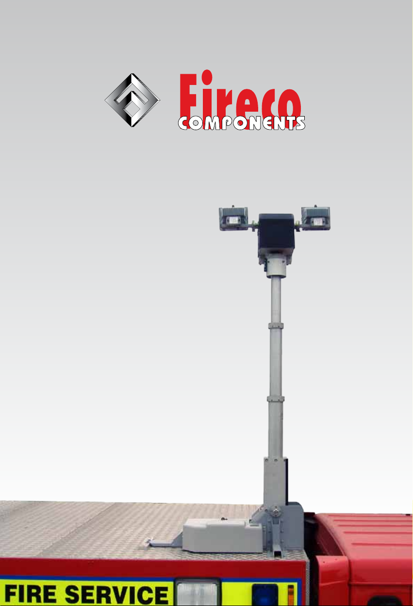
USE AND MAINTENANCE FOR ROOF MASTS
FIXING
POINTS
HOLE DIAMETER 9 mm
HOLE DIAMETER 11 mm
FITTING MODEL ROOF BASE
6 7

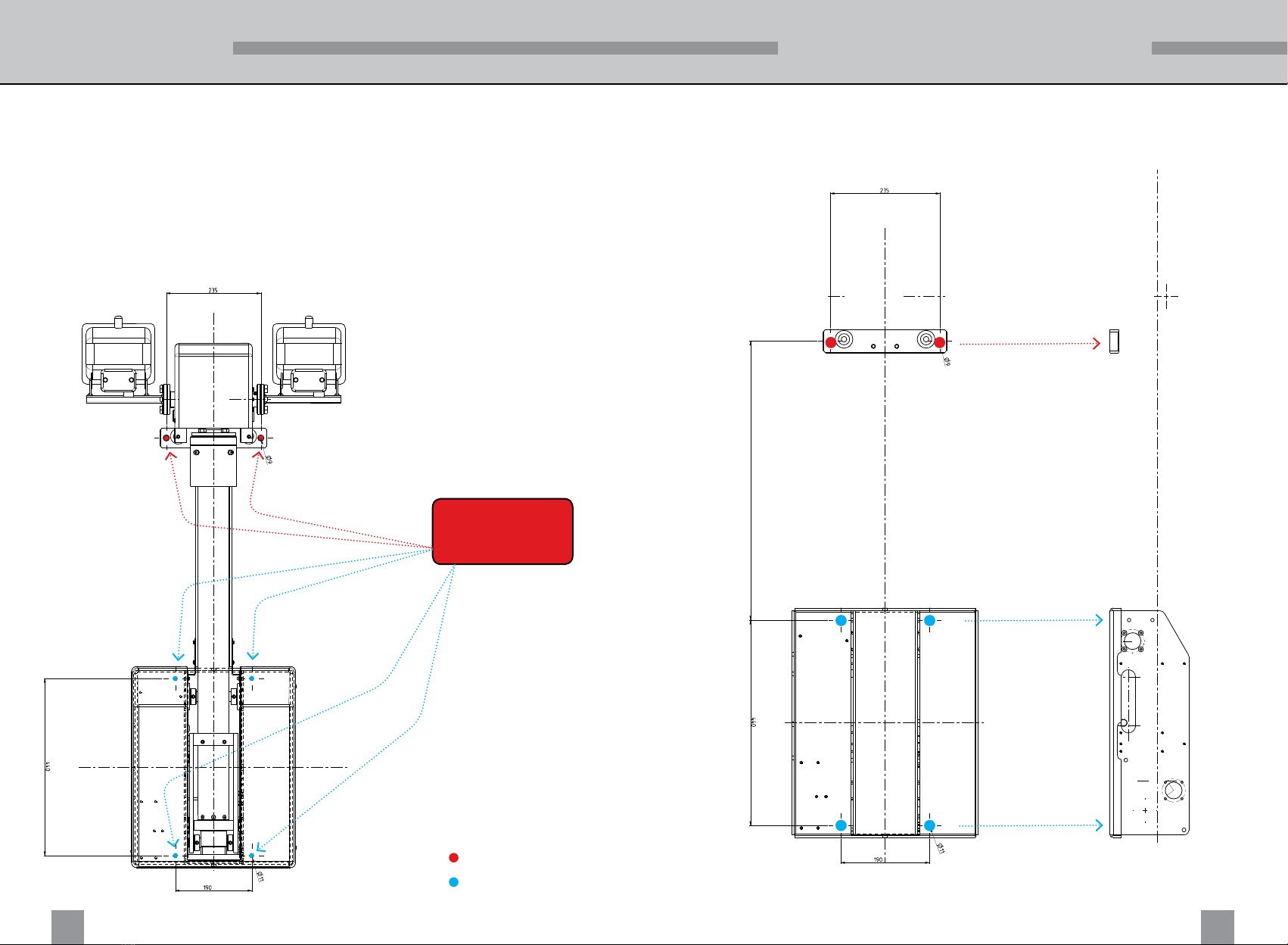
USE AND MAINTENANCE FOR ROOF MASTS
FITTING MODEL ROOF PLUS
FIXING
POINTS
HOLE DIAMETER 9 mm
HOLE DIAMETER 11 mm
8 9
This manual suits for next models
2


