Firegear FG-T-21SS User manual

REV. A Page 1
DO NOT DISCARD. THIS MANUAL
HAS IMPORTANT OPERATING AND
MAINTENANCE INSTRUCTIONS.
LEAVE WITH THE HOMEOWNER.
MODEL:
SERIAL #:
Outdoor Fire Pit T-Burners & Kits
T-Burner Only Description T-Burner Kit Description Natural Gas (NG)
FG-T-21SS 21” T-Burner FG-T-21SSK 21” T-Burner Kit 50,000 Btu’s
FG-T-27SS 27” T-Burner FG-T-27SSK 27” T-Burner Kit 50,000 Btu’s
FG-T-33SS 33” T-Burner FG-T-33SSK 33” T-Burner Kit 75,000 Btu’s
FG-T-45SS 45” T-Burner FG-T-45SSK 45” T-Burner Kit 100,000 Btu’s
FG-T-57SS 57” T-Burner FG-T-57SSK 57” T-Burner Kit 125,000 Btu’s
FG-T-69SS 69” T-Burner FG-T-69SSK 69” T-Burner Kit 150,000 Btu’s
FG-T-81SS 81” T-Burner FG-T-81SSK 81” T-Burner Kit 175,000 Btu’s
FG-T-93SS 93” T-Burner FG-T-93SSK 93” T-Burner Kit 200,000 Btu’s
Installation and Operating Instructions
IF YOU CANNOT READ OR UNDERSTAND THESE INSTALLATION INSTRUCTIONS
DO NOT ATTEMPT TO INSTALL OR OPERATE THIS APPLIANCE
Warning: For Outdoor Use Only
INSTALLATION PRECAUTION:
Fire pit burners require a minimum 18-square inches (per side) of cross ventilation
in an enclosure. Failure to provide proper ventilation can void the warranty.
PN#90132
These re pit burners are manufactured from the factory for Natural gas only. If you intend using LP gas then
you must purchase a LP conversion kit. See Table of Contents for LP converstion kit information.

T- Burner Kit REV. A Page 2
Fuels used in gas red appliances, and the products of combustion such as fuels, contain
chemicals known to cause cancer, birth defects and/or other reproductive harm.
This warning is issued pursuant to the California Health & Safety Code Sec. 25249.1
DANGER
CARBON MONOXIDE HAZARD
This appliance can produce carbon monoxide
which has no odor.
Using it in an enclosed area can kill you.
Never use this appliance in an enclosed
space such as a camper, tent, car or home.
If you smell gas:
1. Shut off gas to the appliance
2. Extinguish any open ame.
3. If odor continues, keep away from
the appliance and immediately call
your gas supplier or re department.
DANGER WARNING
Do not store or use gasoline or other
ammable vapors and liquids in the
vicinity of this or other appliances.
Any LP cylinder not connected for use
shall not be stored in the vicinity of this
or other appliances.
WARNING
Do not leave unattended during use.
Do not use for cooking.
Follow all gas leak procedures in this
manual prior to operation.
WARNING
Improper installation, adjustment,
alteration, service or maintenance
can cause injury or property damage.
Read the installation, operating and
maintenance instructions thoroughly
before installing or servicing this
equipment.
WARNING
If the information in these instructions is not followed exactly, a re or explosion
may result causing property damage, personal injury or death.
FOR YOUR SAFETY
Do not store or use gasoline or other ammable vapors and liquids in the vicinity
of this or other appliances.

REV. A Page 2 T- Burner Kit REV. A Page 3
Specications 4
Preparation for Non-Combustible Structure 5
High Elevation 5
Cross Ventilation Requirements 5
Pipe Sizing Chart 6
Installation into an Approved Enclosure 7
H-Burner Assembly 8
Installing Key Valve / Media 9
Typical Installation Drawings 10
Operation 11
Lighting Instructions 11
Replacement Parts 12
Replacement Parts List 13
Converting to LP Gas 14
Optional Accessories 15
Fire Pit Maintenance 15
Trouble Shooting 15
TABLE OF CONTENTS
All media (i.e. lava rock, lava stones, lava boulders and fire glass) has the potential of
thermal spalling. This is a process that may occur when media is wet and moisture gets
trapped inside of the material due to rapid temperature differences. When this happens
the media has the potential to crack or “pop” outside the fire feature.
WE HIGHLY RECOMMEND COVERING ALL FIRE FEATURES WHEN NOT IN USE
The use of a cover can lessen the impact of thermal spalling; however, heavy rains, high
humidity and the presence of moisture may still cause the media to pop.
ALWAYS USE CAUTION WHEN USING THE FIRE FEATURE
Extra caution should be taken when lighting a fire feature when heavy rains, high humidity
and moisture are present. Light the fire feature; leave the area allowing any moisture in
the media to dissipate. We strongly recommend that during this drying out time that you
monitor the fire feature from a distance. This drying out period should be no less than 30
minutes. Continue monitoring the flame from distance to ensure that all popping has
ceased before fully enjoying the fire.
CAUTION
CALIFORNIA PROPOSITION 65
WARNING
This product can expose you to Chromium, which is
known to the state of California to cause cancer
and birth defects or other reproductive harm.
(For more information, go to www.p65warnings.ca.gov)

T- Burner Kit REV. A Page 4
SPECIFICATIONS
Table 1 Suggested pan sizes and clearance specications
Model:
H-Burner Only/ H-Burner Kit
NG
Orice
BTU’s
NG
LP
Orice
FG-T-21SS/ FG-T-21SSK OAS-NG34 50,000
(14.65kW)
OAS-LP47
FG-T-27SS/ FG-T-27SSK OAS-NG34 50,000
(14.65kW)
OAS-LP47
FG-T-33SS/ FG-T-33SSK OAS-NG29 75,000
(21.98kW)
OAS-LP41
FG-T-45SS/ FG-T-45SSK OAS-NG22 100,000
(29.31kW)
OAS-LP35
FG-T-57SS/ FG-T-57SSK OAS-NG16 125,000
(36.63kW)
OAS-LP31
FG-T-69SS/ FG-T-69SSK OAS-NG11 150,000
(43.96kW)
OAS-LP29
FG-T-81SS/ FG-T-81SSK OAS-NG05 175,000
(51.29kW)
OAS-LP26
FG-T-93SS/ FG-T-93SSK OAS-NG02 200,000
(58.61kW)
OAS-LP22
Table 2 Btu Specications
Pressure NG LP
Min. Inlet 5.0” WC (1.24 kPa) 10.5” WC (2.61kPa)
Max. Inlet 10.5” WC (2.61kPa) 13.0” WC (3.23kPa)
Normal Inlet 7.0” WC (1.74kPa) 11.0” WC (2.73kPa)
Table 3 Gas Pressures
Models:
H-Burner Only/ H-Burner Kit
Pan/Disc
Depth
Burner
Length
Min. Inside
Pan
Dimension
Ground
Level
Side
Wall
Combustible
Ceiling
Combustible
Floor
Center
Hub
Size
FG-T-21SS/ FG-T-21SSK 2 ½” - 3” 21” 24” x 6” 8” 36” 96” 18” ⅞”-1”
FG-T-27SS/ FG-T-27SSK 2 ½” - 3” 27” 30” x 6” 8” 36” 96” 18” ⅞”-1”
FG-T-33SS/ FG-T-33SSK 2 ½” - 3” 33” 36” x 6” 8” 36” 96” 18” ⅞”-1”
FG-T-45SS/ FG-T-45SSK 2 ½” - 3” 45” 48” x 6” 8” 36” 96” 18” ⅞”-1”
FG-T-57SS/ FG-T-57SSK 2 ½” - 3” 57” 60” x 6” 8” 36” 96” 18” ⅞”-1”
FG-T-69SS/ FG-T-69SSK 2 ½” - 3” 69” 72” x 6” 8” 36” 96” 18” ⅞”-1”
FG-T-81SS/ FG-T-81SSK 2 ½” - 3” 81” 84” x 6” 8” 36” 120” 18” ⅞”-1”
FG-T-93SS/ FG-T-93SSK 2 ½” - 3” 93” 96” x 6” 8” 36” 120” 18” ⅞”-1”
Disclaimer: Btu listings are based on 7.0”WC for Natural Gas
and 11.0”WC for Liquid Propane (LP) at the burner orice. Flex
line size and proper gas pipe sizing will also affect Btu’s. As a
result your Btu’s may vary slightly from Table 2 specications.
BEFORE INSTALLING A T-BURNER DETERMINE PAN SIZE TO BE USED:
The T-Burners listed above are not provided with a burner pan for installation. You must provide an appropriate
non-combustible burner pan to install the T-Burner. Suggested burner pans sizes in Table 1 are strictly recommended
based on the T-Burner model size. The pans can be a rectanglar style pan or at disc type. NOTE: It is recommended to
use 304 Stainless Steel. Burner pans should have ¼” drainage holes to prevent standing water in pan and the center hole
for burner connection should be ⅞” - 1” diameter for all sizes.
CAUTION: DO NOT use stiff screen/perforated metal as a burner pan. Some gases are heavier than air and
screen/perforated metal can allow gas to ow downward in an enclosure which could cause delayed ignition or
explosions.
96”/120”
36”
18”
C
L
24”
Max
Overhang
Fig. 1Clearance to combustibles
Description: T-burners are provided with a burner and orice only (i.e. FG-T-21SS) and T-burner Kits are provided with
T-burner, orice, key valve assembly and ex line (i.e. FG-T-21SSK).

REV. A Page 4 T- Burner Kit REV. A Page 5
PREPARING A NON-COMBUSTIBLE STRUCTURE
The re pit it so be installed on a at, stable surface, away from any combustible materials. Install re pit on any level,
outdoor non-combustible enclosure, specied in this manual. NOTE: Do not place re pit directly on grass, dirt, or rocks
this may prevent proper ventilation in Fig. 3. In addition, do not recess the re pit into the ground. Ensure proper water
drainage is also incorporated underneath the re pit enclosure.
HARD PIPING TO FIRE PIT WITHOUT GAS PROXIMITY
NOTE: Refer to the NFPA54 (National Fuel Gas Code) for proper pipe sizing. See gas line sizing chart on page 6 as a
reference.
1. Turn OFF gas supply system. NOTE: All gas connections (except for brass to brass) require the following. Clean pipe
threads using either a wire brush or steel wool. Apply pipe sealant to the ttings before making any connection.
2. Ensure all gas connections are snug, but do not over tighten! BE CAREFUL!
3. Consult a plumber for proper installation to ensure you are providing adequate gas supply for your application.
4. The primary gas shut-off (not supplied) will require a ½” male ared tting to enable connection of the stainless steel
ex gas line supplied with the re pit (see Fig. 7 page 10).
5. Do not place an LP tank inside any re pit enclosure. Locate all propane (LP) tanks outside the enclosure.
6. To prevent performance problems in Propane (LP) re pits, do not use a Propane tank less than 100lbs. capacity.
IMPORTANT
Installation of Natural or LP gas should be done by a qualied installer, service agency or gas supplier.
This appliance must be isolated from the gas supply piping system by closing its manual shutoff valve during any
pressure testing of the gas supply piping system at test pressures equal to or less than ½” psi (3.5kPa).
VENTILATION FOR NON-COMBUSTIBLE ENCLOSURE
Fire pits are subjected to many outdoor elements such as rain,
snow, wind, heat or cold. A minimum of 18 square inches
(per side) of cross ventilation is required to keep the
components in good working order. Use Fig. 3 as guide to
assist to incorporate proper ventilation.
Fire Pit
Enclousure
(2) 6”x12”
Fire Pit
Examples of Cross Ventilation
3 - 2”x3” Slots Per Side or
2- 1” x 9” Slots Per Side or
2- Firegear 6 x12 vents
Cross Flow Ventilation
(Min. 18 Sq. In. Per Side)
Fig. 2 Cross Ventilation Example
HIGH ELEVATION INSTALLATION
This appliance is listed for elevations from 0-4500 feet in Canada
and the U.S. If elevation exceeds 4500 feet it may be necessary
to decrease the input rating by changing the existing burner orice
to a smaller size. Input should be reduced 4% for each 1000 feet
beyond the 4500 feet above sea level. Check with your local gas
utility for assistance in determining the proper orice in your
location. In some cases the heating value may already be
reduced and downsizing the orice may not be necessary.
WARNING: Proper clearances from combustible materials must be maintained from all sides, top and bottom of this
appliance. Use the specications listed in Table 1 and Fig. 2 for proper clearance to combustibles.

T- Burner Kit REV. A Page 6
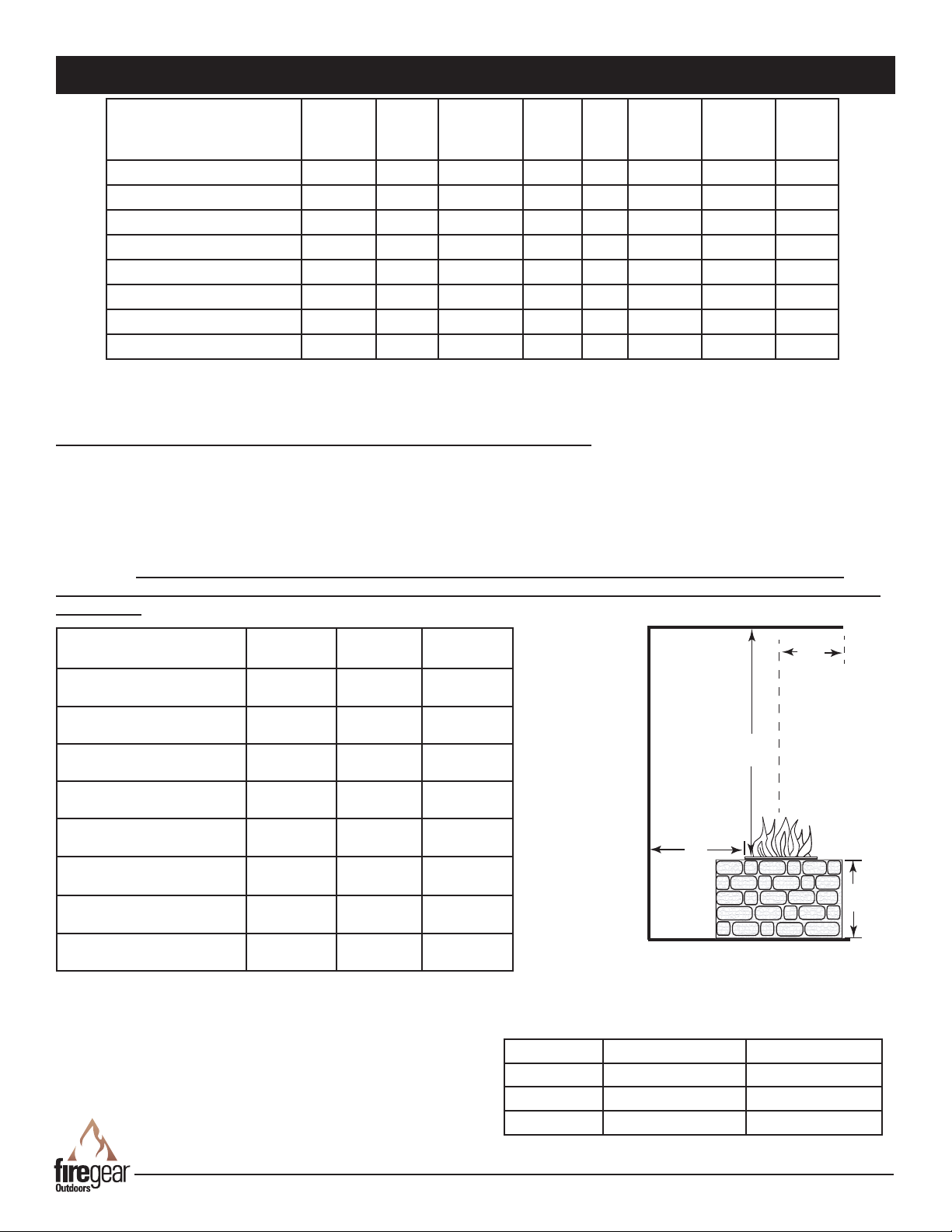
GAS PIPE SIZING CHART
REFERENCE
GAS PIPE SIZING
Length of Pipe in Feet 1/2” 3/4” 1” 1 - 1/4” 1 - 1/2” 2” 2 - 2 1/2” 3” 4”
10 275 567 1071 2205 3307 6221 10140 17990 35710
20 189 393 732 1496 2299 4331 7046 12510 25520
30 152 315 590 1212 1858 3465 5695 10110 20620
40 129 267 504 1039 1559 2992 4778 8481 17300
50 114 237 448 913 1417 2646 4343 7708 15730
60 103 217 409 834 1275 2394 3908 6936 14150
70 89 185 346 724 1086 2047 3329 5908 12050
80 78 162 307 630 976 1811 2991 5309 10830
90 69 146 275 567 866 1606 2654 4711 9613
100 63 132 252 511 787 1496 2412 4281 8736
125 54 112 209 439 665 1282 2083 3618 7382
150 48 100 185 390 590 1138 1808 3210 6549
175 43 90 168 353 534 1030 1637 2905 5927
200 40 83 155 325 491 947 1505 2671 5450
300 37 77 144 303 458 887 1404 2492 5084
NATURAL GAS : PIPE SIZING CHART
•Natural Gas (NG) flow is given in
thousands of BTU/hr. = 1cubic
foot of NG gas - 1000 BTU
•Nominal pressure at the burner
for Natural Gas is 3.5” of water
column. (Typical machine supply
5”-7”)
•Pipe length must include
additional length for all fittings.
Add approximately 5 feet of pipe
per fitting.
•Natural Gas Example: A machine
with a burner that requires
440,000 BTU would need a 1 -1/4”
pipe for a 20” long run.
LIQUID PROPANE : PIPE SIZING CHART
NOTE: The sizing charts above list the specific pipe sizes required for the amount of BTU’s for a new gas line installations. If you
are using an existing gas line you must take into consideration the existing gas line capacities to ensure you will have proper
pressure. This chart is for reference only, we recommend you consult with a Licensed Plumber/Gas Fitter or NFPA54 (National Fuel
Gas Code - current edition) for more details.
Length of Pipe in Feet 1/2” 3/4” 1” 1 - 1/4” 1 - 1/2” 2” 2 - 2 1/2” 3” 4”
10 108 230 387 793 1237 2259 3640 6434 -
20 75 160 280 569 877 1610 2613 5236 9521
30 61 129 224 471 719 1335 2165 4107 7859
40 52 110 196 401 635 1143 1867 3258 6795
50 46 98 177 364 560 1041 1680 2936 6142
60 42 89 159 336 513 957 1559 2684 5647
70 38 82 149 317 476 896 1447 2492 5250
80 36 76 140 239 443 840 1353 2315 4900
90 33 71 133 275 420 793 1288 2203 4667
100 32 68 126 266 411 775 1246 2128 4518
125 28 60 117 243 369 700 1143 1904 4065
150 25 54 105 215 327 625 1008 1689 3645
175 23 50 93 196 303 583 993 1554 3370
200 22 47 84 182 280 541 877 1437 3160
300 17 37 70 145 224 439 686 1139 2539
•Liquid Propane (LP) Gas flow is
given in thousands of BTU/hr. =
1cubic foot of LP gas - 2500 BTU.
•This chart refers to low pressure LP,
after regulation, Standard nominal
pressure at the burner for Liquid
Propane Gas is 11” of water column.
•Pipe length must include additional
length for all fittings. Add
approximately 5 feet of pipe per
fitting.
•LP Example: A machine with a
burner that requires 440,000 BTU
would need a 1” pipefor a 20’ long
run.
Table 4 Gas Pipe Sizing Chart

REV. A Page 6 T- Burner Kit REV. A Page 7
REQUIREMENTS
1. Only non-combustible materials should come in direct contact with any part of the re pit. Underneath area should
be non-combustible or a at level combustible surface according to the clearances specied in this manual.
2. Refer to the NFPA54 (National Fuel Gas Code) for proper pipe sizing. Determine the size of the re pit you are
preparing to install (Refer to page 6, Table 4).
3. Determine the size of the round or square re pit you are preparing to install (Refer to page 4).
4. You must provide a round or square opening out to place the re pit into the non-combustible enclosure. A minimum
burner pan dimension is listed in Table 1.
5. Follow the local code requirements for the gas type being used. This re pit should be installed in accordance with
local codes and ordinances or in the absence of local codes, with the latest National Fuel Gas Code, ANSI Z223.1
NFPA54 or CSA B149.1, Natural and Propane Installation Code in Canada.
6. Fire pits create high temperatures, it is very important to have any combustibles at a safe distance.
7. Do not ll the enclosure with gravel, rock or sand. The enclosure requires free owing air underneath to keep
enclosure cool, provide ventilation to prevent moisture, and provide an outlet for gas in the case of a gas leak.
8. CAUTION: A minimum of 18 square inches of cross ventilation (opposite sides) is required to keep the
enclosure dry.
9. These products are designed for outdoor use only. Not approved for any indoor use or any enclosed space.
10. This re pit is designed to have Firegear Outdoors lava rock or glass media completely covering the burner tube,
so that the burner is not visible. Do not cover more than 1” above the top of burner. Use lava rock a minimum of 1”
diameter as a base to ll the burner pan. DO NOT USE STONE OR RIVER ROCK.
11. Gas lines and ttings must be installed in to the non-combustible structure. All gas connections must be leak tested
before installation of the re pit. Soapy water leak detection is required before regular use of the re pit.
12. Do not use material that will absorb moisture over time and will not release this moisture quickly. Moisture can boil
in this material and can rapidly break apart and cause damage or personal injury.
13. Never leave any other combustible material on top of the re pit. This could cause unsafe operation of this system
and damage to the component that will not be covered under our warranty.
14. Ensure proper water drainage is also incorporated into the re pit enclosure.
INSTALLATION OF FIRE PIT INTO AN APPROVED ENCLOSURE

T- Burner Kit REV. A Page 8
Before you begin installing the T-Burner into a burner pan ensure the center hole is 7/8” to 1-inch in diameter (See Fig. 6).
Ensure to seal the burner nipple and each NPT tting with thread tape or pipe compound. NOTE: Flared ttings
will not require tape or compound on the ared side.
Step 1: Install the T-Burner through the pan (See Fig. 4) then install the OAS and U3-8D-S to the nipple connect inlet gas
line as shown in Fig. 5.
7/8” to 1- Inch Center Hole
Fig. 3 Minimum center clearance hole in burner pan.
ALL T-BURNER MODELS
T-Burner ASSEMBLY
CAUTION: Do not assemble the OAS and U3-8D-S until you are ready to install the T-Burner into the burner pan. The
OAS is 1½” in diameter and would not t the recommended center hole size per Fig. 6 and Fig. 9.
GAS FLOW
T-Burner Side View
Burner Pan
U3-8D-S
OAS (Orifice)
Burner Nipple
Fig. 4 T-Burner Installed into Burner pan/disc.

REV. A Page 8 T- Burner Kit REV. A Page 9
The key valve contents: 1- key valve, 1- key and 1- ange. (See Fig 6). The valve requires a 1¼” round clearance hole in
the non-combustible enclosure wall. See the instructions supplied with the key valve for more specic details.
Note: Be sure to leak test all tting before operation. Fig. 7 on page 10 shows an example of a typical installation.
Primary Gas
Supply
ON
OFF
Fig. 6 Key valve components.
Note: If you did not order a T-Burner kit with a key valve assembly you will need to provide a key valve for the
installation or order one from Firegear Outdoors. See replacement parts list in manual for model numbers.
INSTALLING KEY VALVE
INSTALLATION OF LAVA ROCK/MEDIA INTO BURNER PAN
Install lava rock into the burner pan. Ensure the lava rock is a 1-inch diameter for proper operation. Note: Do not pour
Lava Rock directly from bag. It should be placed naturally and NOT packed in tight. Loose tting is important to ensure
robust ames. Be sure rocks are free of any excessive dust. This prevents the burner pan weep holes from being
plugged and holding water. Cover the burner completely with media but do not make the depth greater than 1-inch over
top of the burner portholes. Other approved Firegear Outdoors media such as glass or Lava Stones can also be used.
MEDIA MUST BE USED DURING OPERATION OF FIRE PIT AT ALL TIMES.

T- Burner Kit REV. A Page 10
Key Valve
Gas Supply
Fire Pit Pan/Disc
Non-Combustible
Fire Pit Enclousure
Shut-O
Burner
Steel Studs
Steel Studs
Steel Studs
Steel Studs
Key Valve Flange
Non-
Combustible
Wall Material
Non-
Combustible
Wall Material
Key Valve
Primary Gas
Supply
K
e
y
V
a
l
v
e
S
i
d
e
V
i
e
w
D
e
t
a
i
l
Fig. 5 Typical installation.
NOTE: Key valve and exible gas lines are
supplied. Gas shut-off is not supplied.
Note: A 1¼” x 2” black iron or galvanized
coupler/nipple (not supplied) can be used
as a spacer between the manual valve
and the valve ange to add additional
support to hold the manual key valve in
place.
Key Valve Flange
Non-
Combustible
Wall Material
Non-
Combustible
Wall Material
Key Valve
Black Iron
Nipple
TYPICAL INSTALLATION DRAWINGS

REV. A Page 10 T- Burner Kit REV. A Page 11
CAUTION: Children and adults should be alerted to the hazards on high surface temperatures and should stay away to
avoid burns or clothing ignition. Young children should be carefully supervised when they are in the area of the appliance.
WARNING: Do not use this appliance if any part has been under water. Immediately call a qualied service technician
to inspect the appliance and to replace any part of control system and any gas control, which has been under water.
OPERATION
SAFETY WARNINGS
1. Never leave the re pit unattended during operation.
2. Clothing or other ammable materials should not be placed on or near the appliance.
3. Any guard or other protective device removed for servicing the appliance must be replaced prior to operating the
appliance.
4. Installation and repair should be done by a qualied service person. The appliance should be inspected before
use and at least annually by a qualied service person. More frequent cleaning may be required as necessary. It
is imperative the control compartment, burners and circulating air passageways of the appliance be kept clean.
5. Inspect the fuel supply connection before each use of the appliance.
6. Temporary storage of this appliance indoors is permissible only if it has been disconnected from its fuel supply
(Natural or L.P. gas line).
WARNING
1. This appliance is hot when operated and can cause severe burns if contacted.
2. Do not burn any solid fuels in this appliance.
LIGHTING INSTRUCTIONS
Key
Fig. 9 Inserting Key into Valve
ON
OFF
Fig. 8 Key valve ange
Butane Lighter
Fig. 10 Lighting re pit with lighter
READ ALL WARNING AND SAFETY INFORMATION ABOVE BEFORE
ATTEMPTING TO LIGHT FIRE PIT
CAUTION: Ensure you have leak tested the re pit before operating.
TURNING ON FIRE PIT
1. Insert key into shut-off valve and secure into square end (See Figs. 8-10).
2. Light a long match or butane lighter and hold it near the burner (see Fig. 10).
3. Turn the key slowly counter-clockwise in key valve (ON position) to allow gas to ow
and simultaneously apply the long burning match or Butane lighter as close to the end
burner as possible to light the re pit.
4. Gas should ignite within 10 seconds or less. If re pit does not light within 10 seconds
turn key clockwise to turn OFF the gas supply. Ensure there is not too much media on
top of the burner that might inhibit gas ow and try again in 5 minutes.
TURNING OFF FIRE PIT
1. Insert key into shut-off valve and secure into square end.
2. Turn key clockwise until it stops.
3. After cooling off install cover.

T- Burner Kit REV. A Page 12
REPLACEMENT PARTS
2
3
Drawings not to scale
5
2a
4
ON
OFF
4a
6
1
7

REV. A Page 12 T- Burner Kit REV. A Page 13
REPLACEMENT PARTS
1 21” T-Burner Burner Only (used with FG-T-21SS or FG-T-21SSK) 1 10615
1 27” T-Burner Burner Only (used with FG-T-27SS or FG-T-27SSK) 1 10600
1 33” T-Burner Burner Only (used with FG-T-33SS or FG-T-33SSK) 1 10601
1 45” T-Burner Burner Only (used with FG-T-45SS or FG-T-45SSK) 1 10602
1 57” T-Burner Burner Only (used with FG-T-57SS or FG-T-57SSK) 1 10603
1 69” T-Burner Burner Only (used with FG-T-69SS or FG-T-69SSK) 1 10612
1 81” T-Burner Burner Only (used with FG-T-81SS or FG-T-81SSK) 1 10617
1 93” T-Burner Burner Only (used with FG-T-93SS or FG-T-93SSK) 1 10618
2
2a
OAS (Orice Air Shutter) for Natural Gas or LP Gas Fire Pits 1 Refer to Table 2
on page 4
3 1/2” Flex Gas Line (46-inch Length) (used with all kits) 1 T200-9898-46
4 High Capacity Key Valve 1 BVL2S
4a Chrome Plated Flange Cover (used with BVL2S key valve) 1 CVR-BVL2CP
5 8-inch Chrome Key (used with all key valves) 1 8” or 12”
6 ½” Flare to 1½” FIP Fitting (used with all DBS Kits) 1 48-88
Item Description Qty. Part Number
See the Firegear Outdoors catalogue for a variety of ttings and ex connectors also available.

T- Burner Kit REV. A Page 14
When converting Burners to LP gas the main burner orice must be kept a minimum of 6-inches away from the burner
connection (nipple) to prevent any back pressure at the LP orice. See Fig. 11 below for details. Note: It is acceptable to
install a 90° elbow, if necessary, to run the gas line the opposite direction (see Fig 12). A 90° elbow is not provided with
the kit.
All NPT pipe threads must be sealed with approved gas Teon tape or pipe compound.
Check for any gas leaks before presuming normal operation after conversion is complete.
CAUTION: Ensure there is ventilation under the burner to provide fresh air for air shutter/orice.
CONVERTING TO LP GAS
Burner Pan
GAS FLOW
½” x 5-inch
Black Iron
Nipple
#113-BS-D5
½” OAS-LP Orifice
½” Flared Fitting
(U3-8D-S)
½” x ½” Coupling
Fig. 11 Proper LP conversion illustration. Fig. 12 Optional LP conversion illustration shows a 90º
elbow (not supplied).
Burner Pan
½” x 5-inch
Black Iron
Nipple
#113-BS-D5 ½” OAS-LP Orifice
½” Flared Fitting
(U3-8D-S)
½” x ½” Coupling
GAS FLOW
½” 90º Black
Iron Nipple
Table 6 LP conversion chart
Converstion Kit Common Parts Btu Ratings LP Orice T- Burner Model
78071 #99-8, #113-SS4-D5,
U3-8D-S
50,000
(14.65kW)
OAS-LP47 FG-T-21SS, FG-T-21SSK
FG-T-27SS, FG-T-27SSK
78072 #99-8, #113-SS4-D5,
U3-8D-S
75,000
(21.98kW)
OAS-LP41 FG-T-33SS, FG-T-33SSK
78073 #99-8, #113-SS4-D5,
U3-8D-S
100,000
(29.30kW)
OAS-LP35 FG-T-45SS, FG-T-45SSK
78074 #99-8, #113-SS4-D5,
U3-8D-S
125,000
(36.63kW)
OAS-LP31 FG-T-57SS, FG-T-57SSK
78075 #99-8, #113-SS4-D5,
U3-8D-S
150,000
(43.96kW)
OAS-LP29 FG-T-69SS, FG-T-69SSK
78076 #99-8, #113-SS4-D5,
U3-8D-S
175,000
(51.28kW)
OAS-LP26 FG-T-81SS, FG-T-81SSK
78077 #99-8, #113-SS4-D5,
U3-8D-S
200,000
(58.61kW)
OAS-LP22 FG-T-93SS/ FG-T-93SSK

REV. A Page 14 T- Burner Kit REV. A Page 15
ACCESSORIES
The following accessories are available from your local Firegear Outdoors dealer/distributor.
Each accessory comes with a separate installation manual. Read each instruction thoroughly before installing.
Lava Stones 1” to 2” size.
Model: FG-LS50 (50lb. bag)
Lava Rock 1” to 2”diameter
Model: FG-LAVA-10 (10lb.bag),
FG-LAVA40 (40lb bag.)
Vent Kits provide 18 square
inches of ventilation per side of
enclosure
Model: VENT-KIT-6X12SS
1. The re pit should be inspected and cleaned before initial use at least annually by a qualied eld service person.
2. Any component that is found faulty must be replaced with an approved component.
3. Any tampering or modifying with the re pit is dangerous and voids all warranties.
4. During winter months in cold climates and various seasons operation the re pit may be affected by weather
conditions. It is recommended to use a ventilated cover overtop of your re pit to protect it from humid/rainy weather
conditions when not in use. Heavy rains/downpours could affect the re pit operation if not covered; if this occurs
ensure you allow the re pit time to dry out before attempting to operate. NOTE: If a combustible type cover is used
over the re pit when not in use be sure to remove it before operation to prevent a severe safety hazard.
5. Over time stainless steel parts can discolor when heated, usually a golden or brown hue. This discoloration is normal
and does not affect the performance of the appliance.
FIRE PIT MAINTENANCE
TROUBLE SHOOTING
Symptom Remedy
Fire pit won’t light 1. Bleed gas line.
2. Ensure all gas supply lines are turned ON.
3. Ensure there is not too much media overtop of burner; it can inhibit gas from owing.
4. Check gas pressure.
Low ame 1. Ensure the base media is at least 1-inch in diameter and top media is no more than 1-inch over
top of burner.
2. Ensure all shut-off valves and key valve is fully open. See page 11; Figure 14
3. Check gas pressure.
4. Check for spider webs blocking the air shutter orice.
Water in my re pit 1. Excess dust/sand material from media may be blocking the weep holes to relieve water.
Remove all media and unplug weep holes. Clean or install new media free of dust and dirt.
2. Ensure re pit enclosure has proper drainage for water and proper ventilation to dry out.
Manual changes often occur, ensure to check the Firegear Outdoor
website for any recent updates and warranty information.
FOR TECHNICAL SERVICE, CALL:
Firegear Outdoors
17322 Gothard St
Huntington Beach, CA 92647
Web Site: www.regearoutdoors.com
(800) 966-8126

T- Burner Kit REV. A Page 16
FIREGEAR LIMITED WARRANTY - 2020
Firegear Outdoors hereby warrants to the end user that products will be free from material and workmanship
defects that prevent safe and correct operation of the product. The warranty commences from date of sale to
the end user for the following period:
CONSUMER RESIDENTIAL APPLICATIONS –MANUFACTURED AFTER 12/02/2019
BURNER SYSTEMS, BURNERS, COMPONENTS AND ACCESSORIES
• LIFETIME WARRANTY ON CONSTRUCTION AND MANUFACTURER DEFECTS
• LIFETIME WARRANTY - STAINLESS STEEL BURNERS AND PANS
• LIFETIME WARRANTY - BRASS BURNERS
• FIVE (5) YEAR WARRANTY - GAS VALVE, SPARK IGNITER, PILOT ASSEMBLIES
• FIVE (5) YEAR WARRANTY - AWS ELECONITC IGNITION SYSTEMS (24VAC, 30 VDC)
• FIVE (5) YEAR WARRANTY - TFS/TMSI ELECTRONIC COMPONENTS
• FIVE (5) YEAR WARRANTY –MT COMPONENTS (KEY VALVE)
• FIVE (5) YEAR WARRANTY - REFRACTORY GAS LOG SETS
• FIVE (5) YEAR WARRANTY - READY TO FINISH/ANF FIRE PIT ENCLOSURES
• FIVE (5) YEAR WARRANTY –SKYTECH MANUACFTURED OPTIONAL CONTROLS
OUTDOOR FIREPLACE –KALEA BAY
• LIFETIME WARRANTY - CONSTRUCTION AND MANUFACTURER DEFECTS
• LIFETIME WARRANTY - STAINLESS STEEL COMPONENTS
• FIVE (5) YEAR WARRANTY - GAS VALVE, PILOT ASSEMBLY, POWER SUPPLY, CONTROLS
• FIVE (5) YEAR WARRANTY –SKYTECH MANUACFTURED OPTIONAL CONTROLS
SANCTUARY SERIES –GFRC FIRE FEATURES
• THREE (3) YEAR WARRANTY - GFRC STRUCTURE
• REFER TO THE APPROPRIATE BURNER SYSTEM FOR WARRANTY
WARRANTY COVERS MANUFACTURING DEFECTS OR STRUCTURAL FAILURE. SMALL STRESS CRACKS AND SURFACE
CRAZING ARE A NATURAL OCCURRENCE IN GFRC PRODUCTS AND NOT COVERED BY WARRANTY.
READY TO FINISH/ANF ENCLOSURES
• FRAME –LIFETIME WARRANTY ON CONSTRUCTION AND MANUFACTURER DEFECTS
ACCESSORIES
• LIFETIME WARRANTY - CONSTRUCTION AND MANUFACTURER DEFECTS
• LIFETIME WARRANTY - STAINLESS STEEL COMPONENTS (LIDS, STAINLESS STEEL COVERS)
• ONE (1) YEAR WARRANTY –ESTOP1-OH, ESTOP2-5H WINDSHIELDS, HOSES AND REGULATORS

REV. A Page 16 T- Burner Kit REV. A Page 17
COMMERCIAL APPLICATIONS –MANUFACTURED AFTER 12/02/2019
BURNER SYSTEMS, BURNERS, COMPONENTS AND ACCESSORIES
• TWO (2) YEAR WARRANTY ON CONSTRUCTION AND MANUFACTURER DEFECTS
• TWO (2) YEAR WARRANTY - STAINLESS STEEL BURNERS AND PANS
• TWO (2) YEAR WARRANTY - BRASS BURNERS
• TWO (2) YEAR WARRANTY - GAS VALVE, SPARK IGNITER, PILOT ASSEMBLIES
• TWO (2) YEAR WARRANTY - AWS ELECONITC IGNITION SYSTEMS (24VAC, 30 VDC)
• TWO (2) YEAR WARRANTY –MT COMPONENTS (KEY VALVE)
• TWO (2) YEAR WARRANTY - REFRACTORY GAS LOG SETS
• FIVE (5) YEAR WARRANTY - READY TO FINISH/ANF FIRE PIT ENCLOSURES
• TWO (2) YEAR WARRANTY –SKYTECH MANUACFTURED OPTIONAL CONTROLS
OUTDOOR FIREPLACE –KALEA BAY
• LIFETIME WARRANTY - CONSTRUCTION AND MANUFACTURER DEFECTS
• LIFETIME WARRANTY - STAINLESS STEEL COMPONENTS
• TWO (2) YEAR WARRANTY - GAS VALVE, PILOT ASSEMBLY, POWER SUPPLY, CONTROLS
• TWO (2) YEAR WARRANTY –SKYTECH MANUACFTURED OPTIONAL CONTROLS
SANCTUARY SERIES –GFRC FIRE FEATURES
• THREE (3) YEAR WARRANTY - GFRC STRUCTURE
• REFER TO THE APPROPRIATE BURNER SYSTEM FOR WARRANTY
WARRANTY COVERS MANUFACTURING DEFECTS OR STRUCTURAL FAILURE. SMALL STRESS CRACKS AND SURFACE
CRAZING ARE A NATURAL OCCURRENCE IN GFRC PRODUCTS AND NOT COVERED BY WARRANTY.
READY TO FINISH/ANF ENCLOSURES
• FRAME –LIFETIME WARRANTY ON CONSTRUCTION AND MANUFACTURER DEFECTS
ACCESSORIES
• LIFETIME WARRANTY - CONSTRUCTION AND MANUFACTURER DEFECTS
• LIFETIME WARRANTY - STAINLESS STEEL COMPONENTS (LIDS, STAINLESS STEEL COVERS)
• ONE (1) YEAR WARRANTY –ESTOP1-OH, ESTOP2-5H WINDSHIELDS, HOSES AND REGULATORS

T- Burner Kit REV. A Page 18
The end-user must provide a bill of sale, canceled check, or payment record to verify the purchase date and to
establish the warranty period. This Limited Warranty shall be valid and limited to the original purchaser only.
WARNING Any modification to the product will void the warranty.
This Limited Warranty shall be limited to the repair and/or replacement of parts that have been proven to be
defective under normal use and service. All warranty claims must be made by the OEM/Distributor/Dealer
account on behalf of the end-user. You may contact Technical Support at 800-966-8126.
Our Technical Service Department must confirm all approved defects. If a defect is confirmed and we approve
the claim, we will replace such parts without charge. This warranty gives you specific legal rights, and you may
also have other rights, which vary from state to state.
The manufacturer may request defective products returned with an RMA (Return Merchandise Authorization)
issued by Firegear Outdoors for specific products, which is considered to be the nature of the defect and or
warranty claim. Product to be returned should; be packed so as not to incur damages during transportation.
Firegear is not responsible for damages on returned items. RMA is valid for thirty (30) days from the date
issued. The RMA must be clearly marked on the outside of the package.
Please check with your local building code department or governing agency for proper approvals before
purchasing. Firegear Outdoors is not responsible for any violation of local codes.
Travel, diagnostic cost, service labor to repair the defect on warranty parts to and from the factory will be the
responsibility of the owner. We will not be responsible for labor charges and/or damage incurred in
installation, repair, and replacement. Firegear is not responsible for Issues related to gas or electrical
installation.
The Limited Warranty is voided if not assembled, installed, and operated as intended. This Limited Warranty
does not cover any defects due to accident, abuse, misuse, alteration, misapplication, vandalism, improper
installation or improper maintenance or service, removal from the original location, or re-installation into
another location, or failure to perform normal and routine maintenance.
Damage due to severe weather conditions such as hail, hurricanes, earthquakes, tornadoes, discoloration due
to overheating, exposure to chemicals (including chlorine and salt), either directly or in the atmosphere, or
very high humidity, is not covered by this Limited Warranty. Costal, humid and/or salt environments are
subject to manufacturer review. All out-of-box claims must be made within 30 days of purchase and must be
made prior to installation. Any product installed damaged will be considered damaged during installation and
not covered under warranty.
There are no other express warranties except as set forth herein. For consumer applications, any applicable
implied warranties of merchantability and fitness are limited induration to the period of coverage of this
Limited Warranty. Some states do not allow limitation on how long an implied warranty lasts, so this limitation
may not apply to you.
For Commercial Applications, the liability of Firegear Outdoors is limited to the express terms of this warranty.
We expressly disclaim any and all implied warranties, including any warranties of fitness for a particular
purpose or merchantability.

REV. A Page 18 T- Burner Kit REV. A Page 19
We are not liable for any special, indirect or consequential damages. Our maximum liability is limited to the
purchase price of the purchased units. Some states do not allow the exclusion or limitation of incidental or
consequential damages, so this limitation or exclusion may not apply to you.
We do not authorize any person or company to assume for it any other obligation or liability in connection
with the sale, installation, use, removal, return, or replacement of its equipment, and or such representation
are binding.
Firegear Outdoors
17322 Gothard Street, Huntington Beach, CA 92647
www.firegearoutdoors.com
Phone: 800-966-8126
This manual suits for next models
15
Table of contents
Other Firegear Burner manuals

Firegear
Firegear DBS-12 User manual

Firegear
Firegear PRO Series User manual

Firegear
Firegear FG-FR-6SS User manual

Firegear
Firegear PRO Series User manual

Firegear
Firegear FG-FR-6SSK User manual

Firegear
Firegear PRO Series User manual

Firegear
Firegear SAN1-30LHMT-N Series User manual

Firegear
Firegear PRO Series User manual
Popular Burner manuals by other brands

Riello
Riello RG1F Installation, use and maintenance instructions

Ecoflam
Ecoflam Max Gas 70 P AB manual

Riello
Riello 20068219 Installation, use and maintenance instructions

Weil-McLain
Weil-McLain UO-3 CV Specification sheet

Elster
Elster Eclipse PrimeFire 100 operating instructions

Riello
Riello RLS Series Installation, use and maintenance instructions