Firegear FGP-305 User manual

REV 8/21/06 Page 1 of 16
FGP-305
INSTALLATION AND OPERATING INSTRUCTIONS
INTRODUCTION
This remote control system was developed to provide a safe, reliable, and user-friendly remote control system for gas heating
appliance. The system can be operated thermostatically or manually from the transmitter. The system operates on radio frequencies
(RF) within a 20'’range using non-directional signals. The system operates one of 1,048,576 security codes that are programmed into
the transmitter at the factory; the remote receiver’s code must be matched to that of the transmitter prior to initial use.
TRANSMITTER The transmitter operates on 2AAA-size 1.5V batteries. It is recommended that ALKALINE
batteries always be used for longer battery life and maximum operational performance.
IMPORTANT: New or fully charged batteries are essential for proper operation of the
multi-function transmitter.
Insert 2 AAA-size 1.5 V batteries into the battery transmitter, positioning the (+) and (-)
ends of the batteries as indicated on the casing. When the batteries are inserted, the
screen below (with similar numbers) will display.
Note: If a LOW battery icon appears on the screen, check the
position of the batteries.
Note: Due to the sensitive temperature-monitoring components
in the transmitter, it may be necessary to allow the transmitter to
stabilize to room temperature before accurate room temperatures
are displayed on the screen. If the transmitter is activated from a
severe cold condition, it can take up to fifteen minutes for accurate
temperature readings to appear.
LCD DISPLAY SCREEN 1. PROGRAM FOR: Flashes when programming days of week and periods of the
day. When in normal state, only current DAY displays. When programming or in
PROGRAM mode, both day and week will appear.
2. DAY –Flashes when current day or day of week is being programmed.
3. PERIOD – Flashes when current period of day or period of week is being
programmed.
4. MODE – Indicates operation MODE of system.
•ON indicates the system is on, either manually, thermostatically, or
program.
•Off indicates the entire system is turned off.
•THERMO indicates the system will automatically cycle ON/OFF,
depending on programmed SET temperature.
•PROGRAM – indicates the system is operating with PROGRAMMED
settings.
5. START AT – Flashes when programming the time to turn system ON.
6. SET – Indicates desired SET room temperature, when in THERMO or
PROGRAM mode.
7. 0F / 0C – Factory programmed in 0F. ( 0C indicates degrees in Celsius)
8. TIME/TEMP – Displays the CURRENT room temperature. In same frame, the
current time will display in AM or PM. You must depress the TIME/TIMER button
to display current time.
9. LOW – Battery power is low. Replace batteries within 2 weeks.
10. TIMER – When displayed, indicates countdown timer in operation.
11. OVERRIDE – Displays when “programmed” SET temperature is overridden.
12. FLAME – Single flame symbol indicates burner/valve is operational.
Review COMMUNICATION SAFETY SECTION under TRANSMITTER section and THERMO SAFETY SECTION under REMOTE
RECEIVER section. These signal/temperature safety features shut down the fireplace system when a potentially unsafe condition exists.
IF YOU CANNOT READ OR UNDERSTAND THESE INSTALLATION INSTRUCTIONS DO NOT
ATTEMPT TO INSTALL OR OPERATE
SU
TEMP
ON OFF THERMO PROGRAM
TIME
AM
START
AT
PROGRAM
FOR SU MO TU WE TH FR SA
MORN DAY EVE NITE
PM
THERMO
ON
LOW
OFF PROGRAM
OVERRIDE HOLD
TEMP
FLAME
TIMER
SWING
123
11
13
7
6
14
8
SET
15
12
10
4
9
5
ROOM SET ROOM SET
SET
AHEAD
BACK
PROG

REV 8/21/06 Page 2 of 16
13. HOLD – Displays when “programmed” SET temperature is overridden and will hold that temperature until cancelled.
14. CP – Displays when CHILD PROOF “LOCK OUT” is engaged. Pressing the UP and TIMER buttons together, engages CP.
15. SWING- Displays in SET frame when setting TEMPERATURE DIFFERNTIAL.
FUNCTIONS
To operate the system, press the MODE button on the transmitter to select the operational MODE
desired.
•ON indicates the system is on, either manually, timed, thermostatically, or program
•THERMO indicates the system will automatically cycle ON/OFF, depending on programmed
set temperature.
•OFF indicates the entire system is turned off.
•PROGRAM indicates the system will automatically cycle ON/OFF in the programmed mode
depending on the 7 day/4 period program that is in memory.
BUTTON SETTINGS
Flip open the plastic cover on the front of the transmitter to expose the “SET” buttons. The flip
cover protects the SET buttons from being changed accidentally. Close the cover after completing
the following settings/ programming.
Flashing numbers on the display indicate the system is awaiting user input, such as using the UP
and DOWN buttons to program a new setting. If no change is made to flashing digits within 15
seconds, the system will complete the procedure last programmed and reset the display to its
normal state.
INITIAL SET-UP PROGRAMMING OF TRANSMITTER
Follow the procedures below, upon FIRST USE of transmitter, setting the following program
options:
•TEMPERATURE SETTING – 0F (Fahrenheit) or 0C(Celsius)
•CURRENT DAY OF WEEK – SU, MO, TU, WE, TH, FR, SA
•CURRENT TIME OF DAY –Hours and minutes
To program settings, first remove the battery cover on the back of the transmitter. If you have not
already installed the 2-AAA batteries, this would be a good time to do so. Note the small push
button at the upper left side of the battery compartment. This is the button used to perform the
initial transmitter programming. You will need to use a paper clip or sharp end of a pencil to
depress this button.
CHANGING THE TEMPERATURE SCALE
1. Press setting button on back of transmitter ONCE and the 0F symbol
will begin flashing on the LCD screen. You may replace the battery
cover at this time.
2. To change
0F to 0C, press the UP or DOWN button on the front of the
transmitter.
3. After setting/confirming the preferred temperature SCALE, press the
SET button on the front of the transmitter.
NOTE: You will need to press the SET button, confirming 0F, if you
want the temperature readings to be in 0F.
SU
TEMP
ON OFF THERMO PROGRAM
SET
AHEAD
BACK
PROG
Button Settings
Setting Button
TIME
SU
AM
SET
AHEAD
BACK
PROG
2
3

REV 8/21/06 Page 3 of 16
SETTING THE CURRENT DAY OF THE WEEK
Following Step 3 above, the symbol SU will begin flashing on the LCD
screen.
1 To change to the current day of the week Press the AHEAD or
BACK button on the front of the transmitter.
2 After setting/confirming the current Day of the week, press the SET
button on the front of the transmitter.
NOTE: You will need to press the SET button, confirming SU, if that is
the current day.
SETTING THE CURRENT HOUR AND MINUTES
1. Following Step 3 on the previous page, the HOUR digits will begin flashing in
the TIME frame on the LCD screen.
2. To set the current HOUR, press the UP or DOWN button setting the HOUR
for the corresponding AM/PM time period.
3. After setting the current HOUR, press the SET button on the front of the
transmitter, and the MINUTE digits will begin flashing on the LCD screen.
4. To set the current MINUTES, press the UP or DOWN button setting to the
correct MINUTES.
5. After setting the HOURS and MINUTES, press the SET button on the front
of the transmitter.
The initial set-up/programming of the transmitter is now complete. Be sure
the slide-on battery cover is reinstalled and proceed to the next step. The
LCD screen will now display in its normal state.
PROGRAM OPERATION OF REMOTE CONTROL
BUILT –IN PROGRAM
The transmitter has a factory program built in. Each day has been broken into four periods
and each period has its own starting time and temperature. A chart of the built- in
programs is at the left.
You may change any of the factory settings by following the procedures below. Should you
wish to return to the factory program, follow the procedures under heading PROGRAM
REVIEW or PROGRAM CANCELLATION depending on which process you select.
PROGRAMMING DAYS/PERIOD OF DAY/SET TEMPERATURES
PROGRAMMING THE TRANSMITTER
The user may change the built-in time and temperature programs to suit their personal schedule. Each day is divided into four
periods: MORNING, DAY, EVENING, AND NIGHT. A blank programming chart is provided to the left to record your customized time
and temperature settings.
If desired, you may change a single day or all seven days that have the built-in factory program. To change one or all seven
days, complete the following steps:
1 Press the PROG button for 4 seconds. The shaded boxes on the
LCD screen with the words PROGRAM FOR and START AT will
begin to flash. The current DAY, PERIOD, TIME and SET
temperature of the BUILT-IN FACTORY PROGRAM will also be
displayed.
PERIOD
DAY MORN DAY EVE NITE TIME/TEMP
SU
MO
TU
WE
TH
FR
SAT
TIME
SU
AM
SET
AHEAD
BACK
PROG
2
3
TIME
SU
AM
SET
AHEAD
BACK
PROG
2
3

REV 8/21/06 Page 4 of 16
NOTE: If the above settings were not previously completed during
the initial SET-UP and PROGRAMMING procedure, then the LCD
screen will display SU, MORN, TIME and SET temperature digits.
You must go back and perform the initial set-up procedure or the
remote will not operate properly in the PROGRAM mode. SEE
PAGE 2.
2 To program
the DAY and PERIOD OF DAY, press the AHEAD or
BACK buttons to display the DAY and PERIOD you wish to
program.
3 When the DAY and PERIOD being programmed displays, then
press the PROG button and the TIME will flash on the LCD screen.
4 To program the START TIME, press the UP or DOWN button.
Programmed start time settings are in 15-minute segments. The
new set time will display on the LCD screen.
5 When the desired START TIME displays press the PROG button
and the SET TEMPERATURE will flash on the LCD screen.
6 To program the SET TEMPERATURE, press the UP or DOWN
button.
7 When the desired SET TEMPERATURE displays, then press the
PROG button.
8 After pressing the PROG button in step 7, the next PERIOD of the
same or next day will display on the LCD screen.
9 To program the next PERIOD follow steps 3, 4, 5, 6 and 7.
10 Continue to follow steps 3, 4, 5, 6 and 7 until all 7 days and the 4
time periods in each day are programmed.
11 Once ALL the programming has been completed, then press the
SET button. The programming data that has been entered will now
over-ride the factory built-in program and operate your remote
control system.
PROGRAMMING NOTE:
Once in the programming process and you want to advance
the programming procedure, you may bypass some of the
DAYS or PERIODS OF DAY, by pushing the AHEAD or BACK
buttons. This allows you to eliminate the need to enter the
TIME and TEMPERATURE for each DAY/PERIOD speeding
up the programming process by skipping some of the ”software
prompts”. Once the LCD screen displays a DAY/PERIOD you
want to reprogram, press the PROG button and follow the
programming steps outlined above.
TIME SET
AM
START
AT
PROGRAM
FOR
SU
MORN
SET
AHEAD
BACK
PROG
1,3 2
TIME SET
AM
START
AT
PROGRAM
FOR
SU
MORN
SET
AHEAD
BACK
PROG
4
5
TIME SET
AM
START
AT
PROGRAM
FOR SU
MORN
SET
AHEAD
BACK
PROG
6
7
TIME SET
AM
START
AT
PROGRAM
FOR
SU
DAY
SET
AHEAD
BACK
PROG
11

REV 8/21/06 Page 5 of 16
PROGRAM REVIEW
If you want to review the settings for either the FACTORY program
and/or your CUSTOMIZED program, you may do so by pressing the
PROG button for one second. To review other
settings, press the PROG button allowing one
second between each press of the PROG button. If
you press the PROG button for 4 seconds, then you
go into the programming process. Press the SET button
should you hold the PROG button too long.
PROGRAM CANCELLATION
Should you want to cancel the CUSTOMIZED program that you have entered and return to the FACTORY program, you may do so. To
cancel a CUSTOMIZED program:
1. Press the SET button to make sure the LCD screen is in normal state.
2. Then press and hold the PROG button and, at the same time, press the SET button for a period of 10 seconds.
3. The customized programs will be cancelled when the display icons/numbers flash with some icons disappearing. The LCD screen
will begin flashing PROGRAM FOR, START AT, and the digits in the TIME and SET frames will begin flashing. This confirms
CUSTOMIZED programs have been cancelled.
4. Push the SET button to return LCD screen to normal state or wait 10 seconds and LCD screen will return to normal state
automatically.
ADDITIONAL PROGRAMMING OPTIONS SWING TEMPERATURE DIFFERENTIAL
The thermo-transmitter operates the fireplace system
whenever the ROOM TEMPERATURE varies a certain number
of degrees from the SET TEMPERATURE. This variation is
called the “SWING” or TEMPERATURE DIFFERENTIAL. The
normal operating cycle of a fireplace system may be 2-4 times
per hour depending on how well the room or home is insulated
from the cold or drafts. A smaller “swing number” increases
the number of cycles so the room temperature is more
constant. A larger “swing number” decreases the number of
cycles, which saves energy, in most cases. The factory setting
for the “swing number” is 2. This represents a temperature
variation of +/- 2 0F (1 0C) between SET temperature and
ROOM temperature which determines when the fireplace will
be activate. The “SWING” number values are:
1= +/- 1 0F (.5 0C), 2= +/- 2 0F (1 0C), 3 = +/-3 0F (1.6 0C).
1 To change the temperature “SWING” setting (1-3), press the
AHEAD + BACK buttons simultaneously to display the current
“SWING”
2 setting in the SET TEMP frame. The word SWING will display on
the LCD screen.
3 Press the UP or DOWN button to change the temperature
differential or “SWING” (1-3). See above for 1-3 “SWING”
temperature values.
4 To store the “swing number”, press the SET button or allow 15
seconds to lapse, and the new “swing number” will be
automatically programmed.
MANUAL CHECK OF “SWING” OR TEMPERATURE DIFFERENTIAL
The operation of the factory set “THERMO SWING” can be checked by adjusting the SET TEMP 2 0F above or below the room
temperature. This will cause the system to turn ON or OFF. Normally the system will only respond to temperature changes every two
minutes. Manually changing the SET temperature will activate the system in less than 10 seconds. If the “SWING” is changed, then a
new room temperature differential will respond. Factory setting of SWING temperature is 2 0F.
TIME SET
AM
START
AT
PROGRAM
FOR SU
MORN
SET
AHEAD
BACK
PROG
1
SWING
SET
AHEAD
BACK
PROG
31
2

REV 8/21/06 Page 6 of 16
OPERATIONAL NOTE: TO CONSERVE BATTERY POWER, CHANGES IN TEMPERATURE ARE ONLY RECORDED EVERY TWO
MINUTES. Additionally, to prevent repeated thermo-cycling of the gas appliance, the sensing unit in the transmitter will only activate
the remote receiver when the temperature change exceeds 2 0F (1 0C) above or below the SET (desired) temperature. However, if
the “SWING” setting has been changed from the factory setting (2 0F /10C), then thermo-cycling will activate at the new setting of the
“SWING” number.
MANUAL CHECK OF THERMO OPERATION
The operation of the Thermo setting can be checked on demand by adjusting the SET temperature 2 0F above or below the room
temperature, which will cause the system to turn ON or OFF, respectively. Normally, however, the system will only respond to
temperature changes every two minutes. NOTE: if “SWING” number has been changed, then activation will occur at the new “SWING”
setting.
When the gas fireplace system is activated, a FLAME icon will display on the LCD screen indicating a signal has been sent from the
transmitter.
OPERATING INSTRUCTIONS
THERMO OPERATION – (Systems operates thermostatically based on SET TEMP setting, ONLY)
SETTING DESIRED ROOM TEMPERATURE
This remote control system can be thermostatically controlled
when the transmitter is in the THERMO mode (THERMO must
be displayed on the screen).
1. To set the DESIRED room temperature, press the
MODE button to place the transmitter into THERMO
mode. THERMO ON or OFF will display.
2. Then press the UP or DOWN button to select the
DESIRED room temperature. The highest SET
temperature is 99 0F (32 0C). The lowest SET
temperature is 45 0F (6 0C).
3. The TRANSMITTER will “sense” the room temperature
every two minutes automatically turning the fireplace ON
or OFF thermostatically.
TEMPERATURE OVERRIDE – (Operates only in PROGRAM
mode)
The user may change the current SET temperature without
changing the programs stored in the transmitter’s memory.
The OVERRIDE feature will be automatically cancelled at the
start of the next PROGRAM PERIOD.
1. To change current SET TEMP, press the UP or DOWN
button (Setting will be cancelled automatically when next
program period begins.) The word OVERRIDE will appear
over the SET frame on the LCD.
2. To cancel temperature OVERRIDE, press SET button.
TEMPERATURE HOLD – (Operates only in PROGRAM
mode.)
The user may override the SET temperature during any period,
adjusting the SET temperature to a CONSTANT new
SET/HOLD temperature.
1. Press the UP or DOWN button to change the SET
temperature to the level desired. The word OVERRIDE
will appear in SET frame on the LCD.
TIME
TU
THERMO
ON
FLAME
PM
SET
AHEAD
BACK
PROG
1
2
TEMP SET
MO
DAY
PROGRAM
OVERRIDE
ON
FLAME
SET
AHEAD
BACK
PROG
1
2
TEMP SET
MO
DAY
PROGRAM
HOLD
ON
FLAME
SET
AHEAD
BACK
PROG
1,2
3

REV 8/21/06 Page 7 of 16
2. To HOLD the new temperature at a CONSTANT setting,
push the UP and DOWN buttons TOGETHER to activate
the HOLD function.
The word HOLD will appear over the SET frame and the
word OVERRIDE will disappear.
3. To cancel OVERRIDE or HOLD, press the SET button.
TIME OF DAY DISPLAY
1 To check the current TIME of day, press the TIMER/TIME
button on the transmitter for less than 1 second. The
current TIME of day will appear in the TIME/TEMP frame
replacing the temperature reading.
2 The TEMPERATURE will reappear in 15 seconds, or you
can press the SET button to cancel the display of the time.
SETTINGTHECOUNTDOWNTIMER
This remote control can operate with a built-in, countdown
timer when the transmitter is in the ON or THERMO mode
(THERMO or ON must be displayed on the LCD screen). DO
NOT operate in PROGRAM MODE, as times are pre-
programmed into the transmitter.
1 Press the TIMER/TIME button on the transmitter for more
than 2 seconds. The word TIMER and 0:15 flash on the
LCD screen.
2 Press the UP or DOWN button on the transmitter to begin
advancing through each of the countdown time options.
Available countdown times are 15 min., 30 min, 45 min, 1
hr, 1 hr 30 min, 2 hr, 2 hr 30 min, and each additional half
hour up to nine hours.
3 To set the TIMER press the SET button on the transmitter.
If the system is ON, it will remain on until the “timer” has
expired. If the system is in the THERMO mode, it will
cancel ON and OFF, as the room temperature requires
until the “timer time” has expired.
4 To cancel the TIMER operation, press the TIME/RTIME
button for more than 2 seconds.
OPERATIONAL NOTE: When the TIMER is used in the THERMO mode, the THERMO operation will discontinue only when the
“countdown time” has expired.
LOW/BATTERY INDICATOR
The word LOW outlined by a battery on the left side of the LCD screen will
appear when battery power has dropped significantly. At this time, approximately
two weeks of battery power remains until the transmitter may experience partial
or complete loss of functions.
NOTE: A reversed battery will activate the LOW battery icon.
TRANSMITTER
OPERATING SAFETY MONITORS: SYSTEMS SHUTDOWN
The remote control operates on RF (radio frequency) signals that are sent by the TRANSMITTER (remote) to the RECEIVER that
operates the appliance. It is recommended that the TRANSMITTER always be located within the 20 foot operating range, preferably in
the same room in which the appliance is located.
TIME
TU
THERMO
ON
FLAME
PM
SET
AHEAD
BACK
PROG
12
TEMP SET
WE
THERMO
HOLD
ON
FLAME
TIMER
SET
AHEAD
BACK
PROG
2
1
3
TEMP SET
WE
THERMO
HOLD
ON
FLAME
TIMER
LOW

REV 8/21/06 Page 8 of 16
THERMO UPDATING FEATURE –TRANSMITTER
This remote control has a THERMO UPDATING Feature built into its software. The THERMO UPDATING Feature operates in the
following manner, but only in the THERMO and PROGRAM MODES:
The transmitter normally reads the ROOM temperature every 2 minutes checking the ROOM temperature against the SET temperature
it sends a signal to the receiver.
COMMUNICATION – SAFETY – TRANSMITTER – (C/S – TX)
This series remote controls have a COMMUNICATION –SAFETY function built into the software. It provides an extra margin of safety
when the TRANSMITTER is out of the normal 20-foot operating range of the receiver.
The COMMUNICATION – SAFETY feature operates in the following manner, in all OPERATING MODES – ON/THERMO/PROGRAM.
At all times and in all OPERATING MODES, the transmitter sends an RF signal every fifteen (15) minutes, to the receiver,
indicating that the transmitter is within the normal operating range of 20 feet. Should the receiver NOT receive a transmitter
signal every 15 minutes, the IC software, in the RECEIVER will begin a 2-HOUR (120-minute) countdown timing function. If
during this 2-hour period, the receiver does not receive a signal from the transmitter, the receiver will shut down the fireplace
being controlled by the receiver. The RECEIVER will then emit a series of rapid “beeps” for a period of 10 seconds. Then
after 10 seconds of rapid beeping, the RECEIVER will continue to emit a single “beep” every 4 seconds until a transmitter
signal is again received. The intermittent 4 second beeping will go on for as long as the receiver’s batteries last which could
be in excess of one year.
To “reset” the RECEIVER and operate the fireplace system, you must press the MODE
button on the transmitter. The word ON must display on the LCD screen. By turning
the system to ON, the COMMUNICATION SAFETY operation is overridden and the
system will return to normal operation depending on the MODE selected at the transmitter.
The COMMUNICATION SAFETY feature will reactivate should the transmitter be taken
out of the normal operating range or should the transmitter’s batteries fail or be removed.
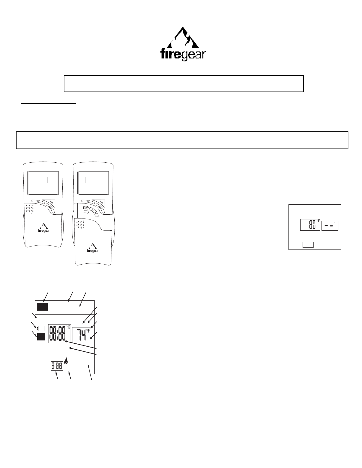
REMOTE RECEIVER
The remote receiver operates on 4 AA-size 1.5V batteries. IT is recommended that ALKALINE batteries be used for longer battery life
and maximum microprocessor performance. IMPORTANT: New or fully charged batteries are essential for proper operation of the
remote receiver.
The remote receiver houses the microprocessor that responds to commands from the transmitter to control the system operation. It
emits one beep when it receives an ON or OFF command manually, but no beep when cycling on and off automatically in THERMO
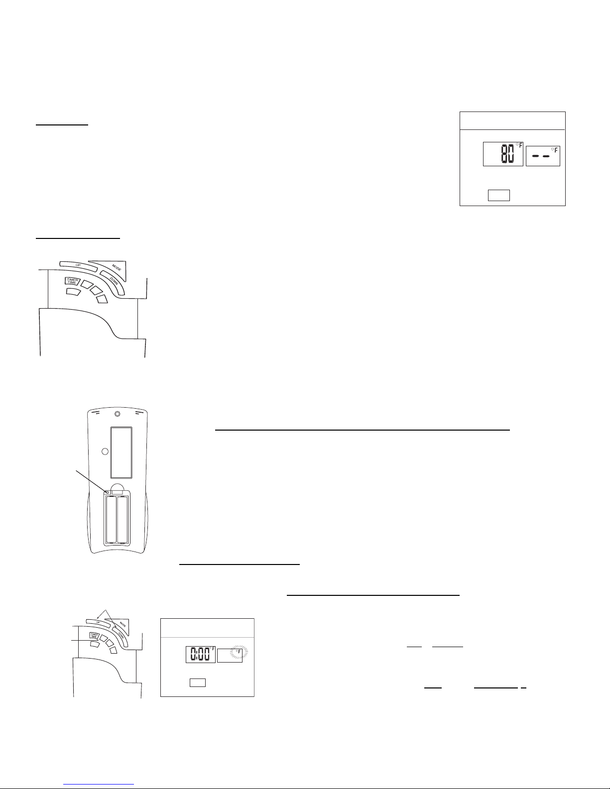
mode. The remote receiver has a 3-position slide switch for selecting the MODE of operation: ON/REMOTE/OFF
•With the slide switch in the ON position (toward the LEARN button), the system will remain on
until the slide switch is placed in the OFF or REMOTE position.
•With the slide switch in the REMOTE position (centered), the system will only operate if the
remote receiver receives commands from the transmitter.
•With the slide switch in the OFF position (away from the LEARN button), the system is off.
•It is suggested that the slide switch be placed in the off position if you will be away
from your home for an extended period of time. If the remote receiver is mounted out
of children’s reach, placing the slide switch in the OFF position also functions as a
safety “lock-out” by both turning the system off and rendering the remote receiver
inoperative.
THERMO- SAFETY FEATURE – RECEIVER (T/S –RX)
This remote control has a THERMO-SAFETY feature that is built into the system’s RECEIVER. This feature is temperature- activated
and provides an extra margin of safety when the RECEIVER is operating where ambient temperatures exceed 130 0F degrees inside
the receiver case.
The THERMO-SAFETY feature, in the RECEIVER, operates in the following manner, when the appliance is in operation.
The receiver is thermally protected from extreme heat conditions. Heat can have negative effect on the operation of the
receiver’s microprocessors.
SET
AHEAD
BACK
PROG

REV 8/21/06 Page 9 of 16
For REMOTE RECEIVERS that operate on BATTERY POWER, these heat conditions can cause batteries to discharge when
temperatures exceed 1150F. Studies show that alkaline batteries, when exposed to a constant temperature of 1150F, can
lose up to 50% of their operating power. When the battery cools down, it will partially recharge itself, but constant heating and
cooling will reduce the battery’s normal life expectancy.
When the ambient temperature at the THERMISTOR, inside the receiver case, reaches 1300F, the THERMISTOR will
automatically shut the appliance down and the RECEIVER will begin emitting a series of 4 “beeps”, every 2 seconds. When
the ambient temperature, at the RECEIVER, drops between 1200F and 1300F, the user can reactivate the appliance by
pushing the MODE button on the transmitter. The word ON must display on the LCD screen. When the MODE button is
pressed to ON, the THERMISTOR “resets” itself and the fireplace will begin operating again. However, the “beeping” will
continue, if the ambient temperature remains between 1200F and 1300F. This “beeping” alerts the user that the RECEIVER
should be repositioned so the ambient temperature drops below 1200F.
When the temperature drops below 1200F, the “beeping” will cease, providing the user has “reset” the THERMISTOR by
pushing the MODE button to ON to operate the appliance, either manually or thermally. Allow sufficient time for the receiver to
cool below 1200F, and then press MODE button to stop beeping.
INSTALLATION INSTRUCTIONS
WARNING
This remote control system must be installed exactly as outlined in these instructions. Read all instructions completely before
attempting installation. Follow instructions carefully during installation. Any modifications of the SKYTECH remote control or any of its
components will void the warranty and may pose a fire hazard.
Do not connect any gas valve or electronic module directly to 110-120VAC power. Consult gas appliance manufacturer’s instructions
and wiring schematics for proper placement of all wires. All electronic modules are to be wired to manufacturer’s specifications.
The following wiring diagrams are for illustration purpose only. Follow instructions from the manufacturer of the gas valve and/or
electronic module for correct wiring procedures. Improper installation of electric components can cause damage to the electronic
module, gas valve and remote receiver.
INSTALLATION
The remote receiver can be either wall-mounted in a standard plastic switch box or placed on or near the fireplace hearth. Preferably,
the remote receiver should be wall-mounted in a plastic switch box, as this will protect its electronic components from both the heat
produced by the gas appliance and potential damage or abuse that can occur if it is left exposed on the hearth. PROTECTION FROM
EXTREME HEAT IS VERY IMPORTANT. Like any piece of electronic equipment. the remote receiver should be kept away from
temperatures exceeding 130 0F inside the receiver case. Battery life is also significantly shortened if batteries are exposed to high
temperatures.
Make sure the remote receiver switch is in the OFF position. It is recommended that 18 gauge stranded or solid wires (not included) be
used to make connections between the terminal wiring block on the millivolt gas valve or electronic module and the wire terminals on
the remote receiver. For the best results, use 18 gauge stranded or solid wire, with no splices and measuring no longer than 20 ft.
WALL MOUNTING
Install 4 AA-size 1.5 ALKALINE batteries in the remote receiver. For best performance, remote receiver batteries should be factory
fresh when installed. Very little battery power is required to operate the remote receiver, but the electronics are tuned to operate best
when battery output is greater than 5.3 volts. Four new AA batteries should provide an output voltage of 6.0 to 6.2 volts. Be sure
batteries are installed with the (+) and (-) ends facing the correct direction.

REV 8/21/06 Page 10 of 16
To attach wall cover plate to receiver box:
1. Position the receiver as shown in diagram to the left with lower tab on
wall cover plate into groove of receiver (Make sure ADJ hole
and LEARN hole on cover plate properly aligns with remote receiver)
2. Pull receiver up and snap into top tab of cover plate.
3. Position the wall cover plate so the word ON is facing up.
4. Install the remote receiver into the plastic switch box using the two
long screws provided. Push the slide Button over the receiver slide
switch only after making sure the remote receiver has LEARNED the
transmitter’s security code (see MATCHING SECURITY CODES). NOTE: slide
5. Button covers both ADJ and Learn holes when properly installed.
NOTE: The remote receiver will only respond to the transmitter when the 3-position slide button on the remote receiver is in the
REMOTE position. If the system does not respond to the battery transmitter on initial use, see MATCHING
SECURITY CODES, and recheck battery positions in the remote receiver.
HEARTH MOUNT
The remote receiver can be placed on the fireplace hearth or under the fireplace, behind the
control access panel. Position where the ambient temperature inside the receiver case does
not exceed 1300F.
NOTE: Slide Button is used for Hearth Mount applications.
WIRING INSTRUCTIONS
A qualified electrician or a gas technician who is familiar with the gas appliance and gas valves that will be operated by this remote
should install the remote control system. Incorrect wiring connections WILL cause damage to the gas valve or electronic module
operating the gas appliance and may also damage the remote receiver.
WIRING MILLIVOLT VALVES
The remote receiver is connected to the millivolt valve using the TH (thermostat)
terminals on the terminal block on the millivolt gas valve. Connect 18 gauge stranded
or solid wires from the remote receiver to the gas valve.
Operation of the remote receiver is similar to that of a thermostat in that both turn the
gas valve on and off based on input signals. A thermostat’s input signals are different
temperatures. The remote receiver’s input signals come from the transmitter.
Connect each of the two wires leading from the TH and TH/TP terminals on the
millivolt gas valve to either of the two wire terminals on the remote receiver. Normally
it does not matter which wires go to which terminal.
WIRING ELECTRONIC SPARK IGNITIONS
The remote control receiver can be connected, in series, to a 24VAC transformer to the TR
(transformer) terminal on the ELECTRONIC MODULE. Connect the hot wire from the 24VAC
transformer to either of the wire terminals on the remote receiver. Connect another wire (not
included) between the other receiver wire terminal and the TH (thermostat) terminal on the
ELECTRONIC MODULE.
Remote Receiver
Cover Plate
(Rear View)
R
E
M
O
T
E
ON
OFF
LEARN
ADJ
.
REMOTE
ON
OFF
LEARN
ADJ.
WALL
Plastic Switch Box
Remote Receiver
Cover Plate
Receiver
Slide
Button
Wire terminals
Remote Receiver
Receiver
Slide
Button
REMOTE
OFF ON
LEARN
ADJ.

REV 8/21/06 Page 11 of 16
SYSTEM CHECK
MILLIVOLT VALVES
Light your gas appliance following the lighting instructions that came with the appliance. Confirm that the pilot flame is on; it must be in
operation for the main gas valve to operate.
•Slide the 3-position button on the remote receiver to the ON position. The main gas flame (i.e., the fire) should ignite.
•Slide the button to OFF. The flame should extinguish (the pilot flame will remain on).
•Slide the button to REMOTE (the center position), and then press the MODE button on the transmitter to change the system to ON.
The main gas flame should ignite.
•Press the MODE button on the transmitter to change the system to OFF. The flame should extinguish (the pilot flame will remain
on).
•Press the MODE button on the transmitter to change the system to THERMO. Advance the SET temperature on the transmitter to
a temperature of a least 2 0F (1 0C) above the ROOM temperature displayed on the LCD screen. With this manual setting, the
normal thermostatic cycle is overridden and the system flame will ignite. Set the SET temperature to at least 2 0F (1 0C) below the
room temperature and the system flame will extinguish in a few seconds. Thereafter, it should continue to cycle on and off
thermostatically approximately every two minutes as the ROOM temperature changes, but only when the temperature differential
between ROOM and SET temperatures differ at least 2 0F (1 0C). (The 2 0F differential is the factory setting.)
ELECTRONIC IGNITION SYSTEMS
•Slide the 3-position button on the remote receiver to the ON position. The spark electrode should begin sparking to ignite the pilot
(the pilot may ignite after only one spark). After the pilot flame is lit, the main gas valve should open and the main gas flame
should ignite.
•Slide the button to OFF. The main gas flame and pilot flame should BOTH extinguish.
•Slide the button to REMOTE (the center position), and then press the MODE button on the transmitter to change the system to ON.
The spark electrode should begin sparking to ignite the pilot. After the pilot is lit, the main gas valve should open and the main gas
flame should ignite.
•Press the MODE button on the transmitter to OFF. The main gas flame and pilot flame should BOTH extinguish.
•Press the MODE button on the transmitter to change the system to THERMO. Advance the SET temperature on the transmitter to
a temperature of at least 2 0F (1 0C) above the ROOM temperature displayed on the LCD screen. With this manual setting the
normal thermostatic cycle is overridden and the system flame will ignite. Set the SET temperature to at least 2 0F (1 0C) below the
room temperature and the system flame will extinguish in a few seconds. Thereafter, it should continue to cycle on and off
thermostatically approximately every two minutes as the ROOM temperature changes, but only when the temperature differential
between ROOM and SET temperatures differ at least 2 0F (1 0C). (The 2 0F differential is the factory setting.)
TIMER
The countdown timer will operate in either the manual ON or THERMO mode. Once the appliance is in an operating mode, set the
countdown timer to turn off in 15 minutes. The timer function will allow operation to continue until the countdown “time” on the LCD
screen expires. After 15 minutes elapses, the system should turn OFF.
If you have any problems with operation, recheck you connections and ensure transmitter batteries are fully charged. If no problem is
found, contact the dealer where you purchased your appliance/remote control.
GENERAL INFORMATION
MATCHING SECURITY CODES
Each transmitter can use one of 1,048,576 unique security codes. It may be necessary to program the remote receiver to LEARN the
security code of the transmitter upon initial use, if batteries are replaced, or if a replacement transmitter is purchased from your dealer
or the factory. When matching security codes, be sure slide button on the receiver is in the REMOTE position; the code will NOT
“LEARN” if the slide switch is in the ON or OFF position. Program the remote receiver to LEARN a new security code by pushing in the
LEARN button on the top of the remote receiver and then pressing the MODE button on the transmitter. A change in the beeping
pattern, at the receiver, indicates the transmitter’s code has been programmed into the receiver. When an existing receiver is matched
to a new transmitter, the new security code will overwrite the old one.
The microprocessor that controls the security code matching procedure is controlled by a timing function. If you are unsuccessful in
matching the security code on the first attempt, wait 1-2 minutes before trying again – this delay allows the microprocessor to reset its
timer circuitry – and try up to two or three more times.

REV 8/21/06 Page 12 of 16
CHILDPROOF “LOCK –OUT” –(CP)
This remote control includes a CHILDPROOF “LOCK-OUT” feature that allows the user to “LOCK –OUT” operation of the fireplace,
from the TRANSMITTER.
SETTING “LOCK-OUT” – (CP)
1. To activate the “LOCK-OUT” feature, press and hold the UP and
TIMER/TIME buttons, together, for 5 seconds. The letters CP will
appear in the TEMP frame on the LCD screen.
2. To disengage the “LOCK-OUT”, press and hold the UP and
TIMER/TIME buttons, together for 5 seconds or more, and the
letters CP will disappear from the LCD screen and the transmitter
will return to its normal operating condition.
NOTE: If the fireplace system is already operating in the ON, THERMO or PROGRAM MODES, engaging the “LOCK-OUT” will not
cancel the operating MODE. Engaging the “LOCK-OUT” prevents only the manual operation of the TRANSMITTER. If in the auto
modes, the THERMO and/or PROGRAM operation will continue to operate normally. To totally “LOCK-OUT” the operation of the
TRANSMITTER’S operating signals, the transmitter’s MODE must be set to OFF.
THERMO FUNCTION
When the transmitter is in the THERMO mode, it should be kept away from direct sources of heat such as fireplaces, incandescent
lighting, and direct sunlight. Leaving the transmitter in direct sunlight, for example, will cause its heat-sensing diode to read the room
temperature higher than it actually is; if in THERMO mode, it may not turn on the appliance even if the ambient ROOM temperature is
below the SET temperature.
BATTERY LIFE
Life expectancy of alkaline batteries in the FGP-305 should be at least 12 months. Check and replace all batteries annually. When the
Transmitter or Wall Transmitter no longer operates the receiver from a distance it did previously (i.e., the transmitter’s range has
decreased) or the remote receiver does not function at all, the batteries should be checked. It is important that the remote receiver
batteries are fully charged, providing a combined output voltage of at least 5.3 volts. The length of the wire between the remote
receiver and the gas valve directly affects the operating performance of the remote system. The longer the wire, the more battery
power is required to deliver signals between the remote receiver and the gas valve. The Transmitter should operate with as little as 2.5
volts of battery power, measuring at the (2) 1.5 volt batteries.
TROUBLE SHOOTING
Should you encounter problems with your fireplace system, the problem may be with the fireplace itself or it could be with the remote
control. Review the fireplace manufacturer’s operation manual to make sure all connections are properly made. Then check the
operation of the remote in the following manner:
1. Make sure receiver batteries are installed properly. If one battery is installed backward, receiver will not operate in remote mode.
Be sure battery output is 2.5 volts or more. (Slide switch is independent of battery condition.)
2. Be sure the transmitter’s batteries are properly installed and that the battery output is 2.5 V or more.
3. Check to make sure the transmitter is communicating with the receiver.
•If the receiver beeps when the MODE button is depressed on the transmitter they are communicating.
•If the receiver does not beep when the MODE button is depressed on the transmitter, you will need to teach the receiver the
code of the transmitter. This is done by holding the LEARN button down on the receiver (NOTE: Slide button, White or Black,
covers the Learn access hole when installed), and at the same time depress the MODE button on the transmitter. A change in
the beeping pattern, at the receiver indicates the transmitter’s code has been programmed into the receiver.
4. Make sure the transmitter is within the 15’-20’ range of the receiver.
5. Positioning of the receiver is important. If the receiver is “enclosed” in a metal surround, the operation of the receiver may be
affected as noted below. Reposition the receiver to improve operating range. It is suggested that a heat shield be installed to
protect the receiver from extreme heat. If the receiver is “enclosed” in a metal surround, this can:
•Cause the RF signal to get lost and not communicate with the receiver.
•Cause the working distance to be shorter than normal.
NOTE: A receiver located in an area, where the ambient temperature inside the case exceeds 130 0F, will cause the THERMO-
SAFETY feature to cut in, requiring you to reposition the receiver to stop the warning beeps, and to “reset” the receiver’s operation.
TU NITE
ON THERMO
TEMP
FLAME
SET
SET
AHEAD
BACK
PROG
1,2

REV 8/21/06 Page 13 of 16
6. Due to handling and shipping of the unit, handling or dropping of the transmitter by the customer, and heat conditions to the
receiver, some units may need an occasional frequency adjustment. This adjustment is made to improve the communication and
operating distance between the transmitter and the receiver. See RECEIVER ADJUSTMENT.
RECEIVER ADJUSTMENT – RECOMMENDED ADJUSTMENT
NOTE: The Slide Button, Gray or Black, covers the ADJ access hole when installed.
A. To adjust at the receiver, use a small slotted screwdriver. Turn the adjustment screw counter-clockwise
about 5 degrees, and 1/8 turn. This should correct the distance problem.
B. If that does not correct the problem, return adjustment screw to original position and then turn adjustment
screw 5 degrees clockwise.
This adjustment is like tuning your radio. If you keep turning the adjustment screw, in either direction, you will
go past the proper setting (tuning).
SPECIFICATIONS
BATTERIES: Transmitter 3.0V- 2 ea. AAA 1.5V, Alkaline
Remote Receiver 6V –4ea. AA 1.5 Alkaline FCC ID No.’s: transmitter –K9L3003; receiver – K9L3301RX
Operating Frequency: 303.8MHZ Canadian IC ID No.’s: transmitter – 2439A-3003; receiver – 2439A-3301RX
FOR TECHNICAL U.S. INQUIRIES
SERVICE, CALL: (888) 220-4333
Website: firegearusa.com
MANUFACTURED EXCLUSIVELY FOR FIREGEAR
FCC REQUIREMENTS
NOTE: THE MANUFACTURER IS NOT RESPONSIBLE FOR ANY RADIO OR TV INTERFERENCE CAUSED BY
UNAUTHORIZED MODIFICATIONS TO THIS EQUIPMENT. SUCH MODIFICATIONS COULD VOID THE USER’S
AUTHORITY TO OPERATE THE EQUIPMENT.

REV 8/21/06 Page 14 of 16

REV 8/21/06 Page 15 of 16
QUICK SET-UP GUIDE
FOR FIREGEAR FGP-305 PROGRAMMABLE TRANSMITTER
This guide is a “short cut” method to SETUP and OPERATE the programmable transmitter. For
detailed instructions for each feature and function, see OWNER”S MANUAL.
INITIAL SET-UPSET FUNCTIONS USING BUTTONS ON FRONT OFTRANSMITTER
1. Remove battery cover.
2. Insert 2AAA batteries.
3. Press SETTING button.
4. Replace battery cover.
All further programming
to be made on front of
transmitter.
OPERATION – Press MODE button on TRANSMITTER to change operating functions.
1 ON indicates the system is on, either manually or
thermostatically.
2 OFF indicates the entire system is turned off.
3 THERMO indicates the system will automatically
cycle ON/OFF, depending on programmed SET
temperature.
4 PROGRAM indicates the system is operating with
PROGRAMME settings.
OTHER OPERATIONS – Press corresponding buttons on TRANSMITTER to activate functions.
TIME OF DAY – Press TIMER/TIME button for less than ONE second.
TIME OPERATION – Press and hold TIMER/TIME button for two seconds.
COUNTDOWN TIME -- pressing UP or DOWN buttons.
NOTE: Press SET button to stop LCD Digits from flashing.
1. SCALE (DEGREE F/ DEGREE C) –
Press UP or DOWN button. Press
SET button.
2. DAY OF WEEK – Press AHEAD or
BACK button. Press SET button.
3. HOUR OF DAY – Press UP or
DOWN button. Press SET button.
NOTE: AM or PM on LCD.
4. MIN. OF DAY – Press UP or DOWN
button. Press SET button.
NOTE: Each SETTING will flash,
separately, on LCD screen. After each
SETTING you must push SET button.
You may not have to change factory
setting, but you must push SET
button.
Setting Button
TIME
AM
WE
OVERRIDE HOLD
4
3
2
FLAME
SU
NITE
PROGRAM
ON THERMOOFF
1234
SET
AHEAD
BACK
PROG
1
SET
AHEAD
BACK
PROG
Button Settings

REV 8/21/06 Page 16 of 16
QUICK PROGRAMMABLE GUIDE
FOR FIREGEAR FGP-305 PROGRAMMABLE TRANSMITTER
This guide is a “short cut” method to PROGRAM the operation of the programmable transmitter. For
detailed instructions for each feature and function, see OWNER”S MANUAL.
PROGRAMMING DAILY OPERATION
NOTE: A FACTORY PROGRAM is already installed in the
transmitter’s software.
You may change the daily “SET TIMES” and “SET
TEMPERATURES” by following the instructions below.
SHORT CUT PROGRAMMING
1. Press PROG button for more than 4 seconds. The PROGRAM
FOR an START AT boxes on the LCD will begin blinking.
2. Program DAY OF WEEK and PERIOD OF DAY by pressing
AHEAD and BACK buttons.
3. Again, press PROG button. START TIME will begin flashing.
4. Program START TIME by pressing UP or DOWN button.
5. Again, press PROG button. SET TIME will begin to flash.
6. Program SET TEMP by pressing UP or DOWN button.
7. Again, press PROG button. The next PERIOD and DAY will
begin to flash.
8. Repeat steps 2 through 7 for all 7 DAYS until each PERIOD OF
DAY is programmed.
9. When all programmed settings are complete, then press the
SET to lock in new programming.
10.To REVIEW, either FACTORY or USER programs, push the
PROG button for ONE SECOND; then scroll through each DAY
and PERIOD OF DAY by pressing PROG button, allowing ONE
SECOND between each press of this button. Press the SET
button when through reviewing the programmed times and
temperatures.
11.To CANCEL user-customized programming, press and hold
PROG and SET buttons together, for 10 seconds; all USER
programs will be cancelled and the FACTORY program will
return
NOTE: Push AHEAD or BACK buttons to advance day and period should you not want to
change each SET time or SET temperature.
DAY PERIOD TIME/TEMP
All 7 Days MORN 6:00 AM 70
Factory-
Programmed
DAY
EVE
NIGHT
8:30 AM 60
3:00 PM 70
11:00 PM 63
TIME SET
AM
START
AT
PROGRAM
FOR SU
MORN
1
46
2
SET
AHEAD
BACK
PROG
9
1
Table of contents
Popular Remote Control manuals by other brands

Schartec
Schartec YET003-S quick start guide

Mitsubishi Electric
Mitsubishi Electric PAR-W31MAA Instruction book

Feit Electric
Feit Electric UCL/REMOTE2 Important Safety Instructions and Installation Guide

Genius
Genius TRAVELER 600 manual

Z-Wave
Z-Wave Z-URC 550EU operating instructions

Fujitsu
Fujitsu UTY-RNRGZ5 Operation manual

Louvolite
Louvolite R1730 operating instructions

Woodward
Woodward easYlite-100 manual

Iconasys
Iconasys LED Studio Light 2.4GHz Wireless Remote... user guide

Sony
Sony RM-VZ950T Service manual

Spektrum
Spektrum DX9 instruction manual

Universal Remote Control
Universal Remote Control ONE FOR ALL 5800CMN manual