Firelands X BOLT 250 User manual

Assembly Manual
Product specications are subject to change without notice.
Due to ongoing development, the actual product may vary from
images shown.
This product is not a toy! (14+) Recommended for ages 14 and
up. Adult supervision required for ages under 18 years old.
Contains small parts, keep out of reach of children 3 years of
age and younger.
Distributed in the
UK by:
J Perkins Distribution Ltd,
Lenham,
Kent, UK
ME17 2DL.
www.jperkins.com
Distributed in Australia by:
Model Engines (Aust.) Pty. Ltd.,
Unit 1, 158-168 Browns Road,
Noble Park,
Victoria,
3174,
Australia.
www.modelengines.com.au
Ph (03) 8793 5555
Distributed in the US by:
Firelands Customer Service/Product
Support
1133 Libra Drive, Lincoln, NE 68512
www.relandsgroup.com
1-800-205-6773
customerservice@relandsgroup.com
MADE IN CHINA
This product contains chemicals known to the State of California
to cause cancer, birth defects and other reproductive harm.
Electronics
Carbon Fiber Manufactured
and Machined in USA
X Bolt FPV Racer Kit AZSZ2903
Packaged and Assembled
in USA

1 x X Bolt Frame (9 pieces)
1 x Flight Controller
1 x Power Distribution
1 x FPV Video Camera
1 x FPV Video Transmitter
4 x 18A Spreed Controls
4 x 2206 2250Kv Brushless Motors
1 x Battery Strap
2 x CW Prop
2 x CCW Prop
6 x 10mm Nylon Standos (F/F)
4 x 12mm Nylon Standos (M/F)
2 x 15mm Nylon Standos (M/F)
4 x Plastic M3 Hex Nuts
8 x 20mm M3 Screws
25 x 6mm M3 Screws
2 x 6mm M3 Grub Screw
4 x M3 Aluminum Thumb Nut
8 x M3 Aluminum 10mm Standos
2 x M3 Aluminum 23mm Standos
2 x M3 Aluminum 35mm Standos
1 x Plastic FPV Camera Mount
1 x Plastic HCT Mount
2.5mm Hex Wrench
3.0mm Hex Wrench
Soldering Iron
Solder
Needle Nose Pliers
Wire Cutters/Strippers
Blue Thread Locker
Sandpaper or Needle File
2.4GHz Transmitter
2.4GHz Satellite or Standard Receiver
5.8GHz Receiver Monitor or Goggles
1300-2200mAh 3-4 Cell Lipo Battery
LiPo Balance Charger
Contents List Tools Needed
Equipment
Kit Contents
2
Advisory
Please wipe o all carbon parts prior to
installation.
If you nd a machined hole that is too
tight, enlarge it slightly using a needle
le or correct size drill bit.

Forward
1234
5
6
1. Camera Plate
2. Battery Plate
3. Top Plate
4. Bottom Plate
5. Camera Mount
6. Motor Arms
Carbon Parts
Washers
On the bottom frame insert four
M3 6mm screws. Use four
washers to keep the PDB (Power
Distribution Board) from touching
the carbon frame.
Place the PDB. Orient the PDB so
that the solder pads for the ESC’s
face the front and rear of the quad.
3

Option 1 - No LED Bar
Install the two M3 35mm alumi-
num standos. Install two M3
10mm nylon standos at center of
frame. Install four M3 10mm alu-
minum standos. All standos are
mounted using M3 6mm screws
from bottom side of frame
Option 2 - LED Bar Install
Replace the two nylon 10mm
strandos with the 10mm alumi-
num standos from the rear of the
frame.
Install the LED bar at the rear of
the frame.
Screw the two M3 6mm grub
screw (threaded rod) into the
10mm aluminum standos at front
of frame. The grub screws should
only be seated a maximum of
3mm into the stando.
Use a drop of blue thread lock on
the grub screw.
Locate the plastic camera mount
and position it on the frame with
the two M3 holes facing forward.
Place a washer on each M3 screw
prior to screwing the camera
mount in place from the bottom of
the frame.
4

Locate the carbon ber camera
mount plate and FPV camera.
Unscrew the lens from the camera
and insert through the hole on the
camera mount, rescrewing the
lens back onto the camera base.
Focusing the camera will be per-
formed after the X Bolt is assem-
bled. Focus is accomplished by
screwing the lens in/out. The lock
ring will x the position of the cam-
era to the camera mount.
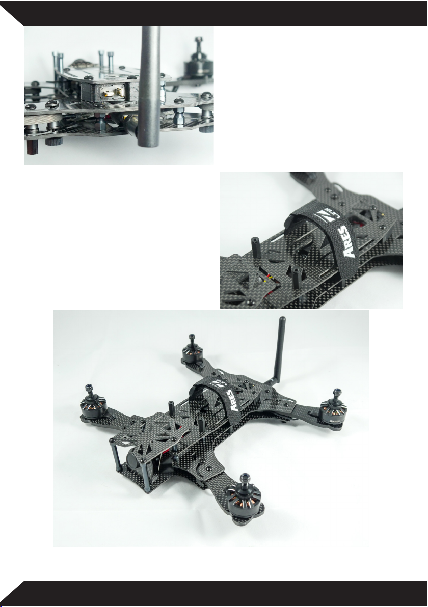
Mount the camera plate to the
plastic camera mount using two
M3 6mm screws.
Note that the camera power
connection is located nearest the
frame. (See Photo)
HCT mount option
Locate the carbon ber top plate.
Install three M3 10mm standos
as shown in photo to right. Locate
the two HCT plastic mount halves.
Install bottom half to the frame
using M3 6mm screw as shown in
photo at right.
5

No HCT mount option
Locate the carbon ber top plate.
Install four M3 10mm standos as
shown in photo to left. Install the
standos with M3 6mm screws
from the bottom side of frame.
Locate the 90 degree header pins.
Solder in place to channels 1-4 on
the ight controller. These are the
4 speed control connections.
NOTE: Double check polarity
marked on the ight controller for
your ESC’s
Satellite Receiver Option
Leave yourself 3” of wire to the
satellite receiver. Solder the three
leads to the ight controller.
External Receiver Option
Locate the wire loom and header
pins as shown in photo to right.
Solder header pins to ight con-
troller
6

Discard JST Plug
Cut 2-1/2” Long
Retain for
later step
Locate the VTX power wire with
the JST plug installed. This wire
will need to be modied for two
applications in the following steps.
Cut the JST plug o close to the
connector. Discard the plut. From
the remaining wire, cut a section
of wire 2-1/2” long. You will use
this wire to power the ight con-
troller from the PDB later in the
manual.
The remaining wire with the white
plug attached will power the VTX
and camera simultaneously.
Solder the VTX power leads to the
ground and 12V tabs on the PDB
as shown in photo to left.
Locate the 4” piece of 16 AWG
wire and cut in half. Solder one
end of each with to the PDB.
Leave the other end of the wires
unattached. These will be soldered
to the HCT plug after the wires are
fed through the frame.
NOTE: Maintain proper polarity.
7

Locate the four 18A brushless
ESC’s.
Solder the ESC power leads to the
PDB as shown in the photo to the
right.
NOTE: Maintain the correct polari-
ty as marked on the PDB.
Locate four 2206 Brushless mo-
tors and hardware.
Locate the carbon ber arms and
match the holes on the motors to
the holes on the arms. If they do
not match, ip the arm over.
8

Using a needle le or sandpaper
ease the edges of the hole in the
arms to avoid chang the motor
wires.
Feed the wires through the hole
and mount the motor to the arm,
using the screws provided with the
motors.
9

Option 1 Expert
Solder directly to the ESC. Make 2
slits on the sides of the ESC and
fold back the heat shrink to ex-
pose the 3 solder pads.
NOTE: Use caution when solder-
ing next to FETS.
Option 2 Intermediate
Splice ESC and motor wires
together as shown in the photo.
Only cut the wires from the ESC,
do not cut the motor wires. Cover
exposed solder joints with heat
shrink (not included).
Add top plate and feed the VTX
cable through the frame.
If you choose to add the optional
buzzer it should be installed at this
point.
In this step we will use the 2-1/2”
wires that you cut from the VTX
power cable earlier.
Solder these wires from the 5V on
the PDB to the ight controller.
10

Washers
Washers
Spacers
Thumbscrew
Standoff
Before you install the top plate you will need to install the motor arms. To
complete this step you will need.
8 M3 20mm screws
8 M3 aluminum spacers
24 Nylon washers
4 M3 Thumb screws
4 10mm Nylon standos F/F
Arm Assembly Sequence
11

Install the two M3 23mm standos.
These will thread onto the grub
screws that you installed earlier.
Wrap the VTX with the provided
piece of heatshrink. This will pro-
vide protection for your VTX.
12

Plug in all your components. The
camera, VTX, satellite receiver
and ESC’s.
Double check ESC polarity.
Diagram shows channel selection
for your ESC’s and motor rotation
direction.
Refer to the diagram to the right.
At this point you should have the
top and bottom plates assembled.
Install M3 nylon hex nuts to secure
the ight controller.
Fit battery tray over 23mm stand-
os. Secure with ve M3 6mm
screws.
13
The HCT plug adapter helps clean
up wiring and holds the battery
leads in place.
Locate two 15mm nylon standos
M/F. These are installed on the
battery tray as shown in photo to
right.
These are to protect the battery in
the event of a crash.
Locate the camera plate and install using four M3 6mm screws.
At this point you are ready to set up in Cleanight.
14

The download and installation of Cleanight is beyond the scope of this
assembly manual. Please go to: Cleanight.com for latest software. An addi-
tional source of good information is RCGroups.com
30-Day Limited Warranty Term Period:
We warranty that the Product(s) purchased (the “Product”) will be free
from defects in materials and workmanship when the product is new
(before being used) for the limited warranty term period, 30 days, from
the date of purchase by the Purchaser.
If you believe a defect in material, workmanship, etc. was not
apparent when the Product was new and only became evident after
the Product was used, take the following steps. If you purchased the
Product at a HobbyTown store, please contact your local HobbyTown
store for warranty support and/or service. If you purchased the
Product from the Firelands website, use the contact information found
under the Support heading to contact Firelands directly.
If you contact Firelands, you may be asked to send the product
to Firelands, at your cost, for inspection. Provided the warranty
conditions have been met within the warranty term period, the
components that are found to be defective, incorrectly manufactured
or assembled may be repaired or replaced, at the sole discretion of
Firelands. Your warranty item will be returned to you at Firelands’
expense. In the event your product needs repair or a replacement
part that is not covered by this warranty, your local HobbyTown store
or Firelands can assist you with support and in obtaining the genuine
replacement parts to repair your Product. Firelands will charge $40.00
per hour plus the cost of replacement parts to service your vehicle if
after contacting you, you so authorize such repairs. Your product will
be returned to you at your expense.
If you purchased your Product from a HobbyTown Internet site not
aliated with a local store, please consult that site for its support and
service policies. You can also nd more information at:
www.Hobbytown.com
or by emailing customerservice@relandsgroup.com
or call 800-205-6773
15

www.Ares-RC.com
© 2016
Rev. 1.0
1/16
Table of contents


