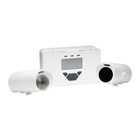
Fireray 2000 Installation and user guide

DOCUMENT CONTROL NUMBER /
© 2001 Tyco Electronic Product Group PAGE 1 of 5
Registered Office: 19-21 Denmark Street, Wokingham, Berks RG40 2QE
FIRERAY 2000
01B-05-S1
02 1/01
EQUIPMENT:
PUBLICATION:
ISSUE No. &DATE:
«¥¥³¸¾¯¼¸«¾³¹¸«¶¥¶¾®¥¹·º«¸Ã
FIRERAY 2000 OPTICAL BEAM SMOKE DETECTOR
SERVICE AND MAINTENANCE
1. GENERAL
This document details the routine servicing and maintenance
procedures and provides a fault finding guide for the Fireray
2000 optical beam smoke detector.
The publication comprises:
Yearly checks
Fault finding guide
Alignment procedures
Testing
Spares list
When an incorrect response is obtained from a check, locate and
rectify the fault as described in Section 3.
When returning a faulty unit or PCB for repair, package it in the
bag that was used for its replacement.
2. ROUTINE CHECKS
The recommended routine checks must be carried out as stated.
2.1 YEARLY CHECKS
Inspect the Control Box, Transmitter and Receiver Units for
damage and ensure they are physically secure.
Clean the lenses on the Transmitter and Receiver Units. (If the
units are installed in a ‘clean area’ or dust free environment the
lenses need be cleaned only every two years).
Align and the test system as necessary.
3. FAULT FINDING GUIDE
This section details some of the possible faults which may occur
during testing of the Beam Detector Set. Most of the faults can
be easily rectified.
If the unit is suspected as faulty, retry the alignment procedure.
If the Beam Detector Set is still faulty replace the Beam
Detector Set with a new one.
If the problem persists, contact the Helpdesk at Sunbury.
Table 1 lists the internal controls and their function.
3.1 POSSIBLE CAUSES OF FAULT ALARMS
a) Receiver placed in the Reset state. Check that
the Test/Reset Switch (Fig. 1) is set to OFF.
b) The beam between the Transmitter and the
Receiver is obscured for more than 94% of the
beam area for one second. Check the beam is
not obscured or that the round glass areas on
the Transmitter or Receiver are dirty. Clean as
required.
c) Signal Level Control set too low at the
Receiver. Turn control (RV1) clockwise.
d) Receiver in Test mode. Ensure the Test/Reset
switch set to OFF.
e) Misalignment of the Transmitter and Receiver
detectors. Re-align as in the Alignment
procedure.
f) Loss of power. Check out the power supplies.
g) Source of infra-red setting of the alarm. Check
for sources of infra-red. For example: heat
emitting lights (eg, incandescent light bulbs),
direct sunlight, heaters and radiators at close
proximity to detectors.
CONTROL FUNCTION
Signal
Level (RV1)
Alters the gain of the received signal from
the transmitter. If the gain is set too low the
Beam Detector Set will not work correctly.
Do not set to maximum position in
NORMAL working mode.
Test / Reset
Switch
Sets the AGC level for the alignment checks
(ON) and arms the Beam Detector Set after a
fire alarm (OFF). Reset can also be done by
removing the power for 2 seconds or by
connecting the external reset input to 0V.
Test/Reset switch is normally in the OFF
position.
Table 1 Controls and their Function

FIRERAY 2000
01B-05-S1
02 1/01
PAGE 2 of 5
Table 2 gives the meaning of the LED indications on the PCB in the Control Box - see Fig 1.
*When the received signal level changes, either an increase or decrease by more than 10%, the corresponding Signal High
(LED 2) or the Signal Low (LED 3) will come ON and an AGC change is requested.
If this request is continuous in each time period (9 hours in increase and about 2 minutes to decrease) the AGC responds
automatically by changing the receiver gain in order to bring the received signal level back to the nominal required level. Only
one stage gain (10%) is affected.
When 15 stages of the AGC gain have been used, ie, the gain increased, the fault relay is turned on then off at a rate of one
per 2 seconds (0.5Hz). The fire alarm will have no further levels of gain compensation available and must not be used.
Note: If maximum AGC gain is reached the alarm will not be reliable and must not be used.
If the signal is reduced any further then the alarm will be signalled.
Check any causes of reaching the AGC limit, such as dirty transmitter or detector round glass area or misalignment.
Clean the glasses thoroughly and check alignment.
LED INDICATION MEANING OF INDICATION ACTION
Fire Alarm
front panel (RED)
When ON smoke present for 5 seconds.
(40% to 93% obscuration of IR beam).
Wait for conditions to clear and reset the unit by
switching OFF/ON/OFF on Test/Reset switch
Both Signal High and
Signal Low lit
Normal for initial calibration state, both LEDs
should switch off within 45 seconds.
Signal High
(GREEN)
Increase of about 10% of signal input (by AGC) Ensure that the AGC will reduce the gain to bring
down the signal down to the nominal level
Signal Low
(GREEN)
Loss of about 10% of signal input Ensure that in normal operation the AGC will
increase the gain to bring the signal up to nominal
Fault
(YELLOW)
1 ON when maximum Gain is reached No more levels of compensation are available*
2 ON when Reset switch is ON Ensure Test/ Reset switch is in Test position when
returning the detector to normal operation
3 ON if the Both Signal High and Signal Low
fail to extinguish after the 45 second calibration
period.
Faulty unit
Table 2 LED Indication (Circuit Board in Control Box)

FIRERAY 2000
01B-05-S1
02 1/01
© 2001 Tyco Electronic Product Group PAGE 3 of 5
Registered Office: 19-21 Denmark Street, Wokingham, Berks RG40 2QE
EQUIPMENT:
PUBLICATION:
ISSUE No. &DATE:
«¥¥³¸¾¯¼¸«¾³¹¸«¶¥¶¾®¥¹·º«¸Ã
Fig. 1 PCB Layout

FIRERAY 2000
01B-05-S1
02 1/01
PAGE 4 of 5
4. ALIGNMENT
The detectors can be aligned by either using a dc voltmeter,
which is positioned at the Transmitter head and connected
via a 2-core cable to the Control Box or an Alignment Aid
which can be substituted for the voltmeter.
.
Fig. 2 Alignment Aid
The Alignment Aid (Fig. 2) is lighter and more robust than a
meter and provides a convenient method of aligning the
detector heads. The display LED flashes at a faster rate when
correct alignment is achieved.
Align the detector heads as follows:
a) Switch on the 24V dc Supply to the Control
Box and the Transmitter/Detector.
b) Ensure the Test/Reset Switch on the Control
Box is set to OFF.
c) Set the Test/Reset Switch to ON.
d) Check the Signal Level control RV1 in the
Control Box is set to the mid-way position.
e) The High Gain (LED 3) and Low Gain
(LED 2) may both be lit.
Note: At this stage other LEDs in the Control Box may
be lit. This is due to the beams not being aligned
exactly.
f) Connect the Alignment Aid or dc voltmeter
as shown in Fig. 1 using 2-core cable.
g) Adjust the Transmitter head horizontally and
vertically so that the receiver detects the
beam in the round glass area such that either:
i) The Alignment Aid LED flashes at a high
rate - adjust for the fastest flashing rate.
ii) Or if using a voltmeter, adjust for a
maximum reading. (A no-signal reading
is approximately 2.6 volts).
h) When this has been done fully tighten the
screws holding the receiver and transmitter
to the ceiling brackets. Ensure that all
fixings are firmly tightened. Re-check the
alignment aid for faster flashing of the light
(to check the Beam Detector Set is working
correctly).
i) At the Control Box adjust RV1 until the
High Gain (LED 2) just goes off.
j) Switch off the power and disconnect the
Alignment Aid or voltmeter.
k) Set the Test/Reset switch to the off position.
Wait at least 45 seconds before performing
any tests.

FIRERAY 2000
01B-05-S1
02 1/01
© 2001 Tyco Electronic Product Group PAGE 5 of 5
Registered Office: 19-21 Denmark Street, Wokingham, Berks RG40 2QE
EQUIPMENT:
PUBLICATION:
ISSUE No. &DATE:
«¥¥³¸¾¯¼¸«¾³¹¸«¶¥¶¾®¥¹·º«¸Ã
When the detector heads are fitted for retro-reflective
operation the alignment procedure is as for normal operation
but with an additional test as follows:
When the system is aligned and in operating
mode block off the reflector at the reflector
end. The detector should go into fault
condition. If the detector does not go into fault
condition then it is possible that the signal is
being returned, not by the retro-reflector, but by
some other reflecting surface.
5. TESTING THE BEAM DETECTOR
SET
The following tests must be carried out after the first
installation, after any maintenance, or after every fire or fault
alarm to ensure fail-safe operation of the Beam Detector Set.
Supplied inside the Control Box is an acetate test card (filter)
with black markings on it which is used to provide
obscuration of the beam during tests.
Note: After the tests have been performed this
acetate card should be held with the system log
book and not inside the Control Box.
5.1 SMOKE ALARM TEST
Proceed as follows:
a) Hold the test filter in the beam path
b) After approximately 9 seconds:
i) the Fire Relay contact operates (the relay
contacts will click once as it operates).
ii) the Fire alarm LED (red) on the front panel
will light.
c) Remove the test filter, the alarm will reset in
approximately 4 seconds (unless in latching
mode).
Fig. 3 Connection of Alignment Aid
d) Reset the Beam Detector Set either by:
i) Moving the Test/Reset switch to OFF, then
ON and then OFF, or
ii) Disconnecting the power for 2 seconds, or
iii) Taking the External Reset terminal to 0 volts
for one second.
e) The Beam Detector Set is now reset and armed.
5.2 FAULT ALARM TEST
Proceed as follows:
a) Totally obscure the beam with an opaque
object such as a piece of card.
c) After about 10 seconds check that Fault LED
(LED 1) lights, and the fault relay contacts
change state.
d) Remove the Test Card obscuring the beam.
e) Check that the Beam Detector Set resets itself
automatically within 4 seconds.
f) Secure the front cover, the Beam Detector Set is
now reset and armed.
Note: After the tests have been performed the recorded
values should be held with the system log book
and not inside the Control Box.
6. ORDERING INFORMATION
Fireray 2000 complete: 516-015-006A
Fireray 2000 complete: 516-015-006T
LPBD520: 557-180-217
Retro-Reflector (TKS 100 x 100): 516-015-007
Alignment Aid: 516-015-008
7. ASSOCIATED PUBLICATIONS
05A-02-S1 FIRE SYSTEMS - GENERAL SERVICE AND
MAINTENANCE INSTRUCTIONS
CB/jm
12th January 2001
Table of contents
Other Fireray Smoke Alarm manuals
Popular Smoke Alarm manuals by other brands
elsner elektronik
elsner elektronik Salva KNX TH Technical specifications and installation instructions

Weller
Weller WFE 2ES operating instructions

FireClass
FireClass Prescient III owner's manual
Visonic
Visonic SMD-426 installation instructions
American Sensor
American Sensor SA379 user manual
Brooks
Brooks EIB170RFAU Install
