manuals.online logo
Brands
  1. Home
  2. •
  3. Brands
  4. •
  5. NAPCO
  6. •
  7. Smoke Alarm
  8. •
  9. NAPCO FIREWOLF FW-2S User manual

NAPCO FIREWOLF FW-2S User manual

FW-2S Wiring Diagram
Connect wiring to the bases as shown in
the wiring diagram at right.
CAUTION: Do not mix smoke detec-
tor types or dry contact closure de-
vices (including thermal detectors,
pull station or water flow devices) on
the same zone.
CAUTION: Connect wiring to termi-
nals as shown. Do not loop wire un-
der terminals. Break wire run to pro-
vide supervision.
ADDITIONAL CAUTIONS:
●Do not use looped wire under ter-
minals 2 and 5. Break wire run to
provide supervision of connec-
tions.
●Do not attempt to disassemble
this factory-sealed smoke detec-
tor. The detector is not intended
to be opened for servicing.
Opening the detector head will
void the warranty.
●To prevent detector contamina-
tion and subsequent warranty
cancellation, smoke detector must remain covered until installation area is clean and dust free.
●See the FACP installation instructions for the maximum number of detectors permitted per zone and for specific wiring
terminal numbers.
●Not suitable for installation in areas where air velocities exceed 300 ft/min.
●Ensure the end-of-line device shown in Fig. 1 (and 1a) is compatible with the control panel.
INSTALLATION INSTRUCTIONS
FW-2S Smoke Detector
FW-2SHead
FW-2SBase
These installation instructions are for the FW-2S FIREWOLF Smoke Detector with internal sounder, FW-2SHEAD and FW-2SBASE.
CAUTION
Install this and all life safety devices in accordance with
applicable NFPA standards, local codes, and the authori-
ties having jurisdiction. Failure to follow these instructions
may result in failure of the detector to initiate an alarm con-
dition. Napco Security Systems, Inc. and the original
equipment manufacturer, are not responsible for detectors
that have been improperly installed, tested, or maintained.
For testing and cleaning information, refer to these instruc-
tions and/or call the NAPCO fax request line at (631) 842-
3291. Also refer to NFPA-72 Chapter 5 for Automatic Fire
Detectors for installation guidelines and Chapter 7 for test-
ing and maintenance requirements.
SPECIFICATIONS SMOKE DETECTOR DATA
Detector Model FW-2S
Type of Detector Photoelectric
Working Voltage 8.5 - 14VDC
Voltage Waveform Filtered DC 15% ripple max.
Maximum Surge Current 100µA
Average Standby Current 43.6µA @ 12VDC
Maximum Alarm Current 60mA
Compatibility Identifier FW-2S
Sensitivity Test Feature Built-In Test Feature
Control Panel Compatibility See control panel installation instructions
Note: As per UL listing requirements, open-area smoke detectors are intended for mounting on a
ceiling no less than 6 inches from a wall or mounting on a wall no less than 4 inches and no more
than 12 inches from a ceiling.
Detector Head Model FW-2SHEAD
Detector Base Model FW-2SBASE
© NAPCO 2010 WI1805A 04/10
The National Fire Protection Association (NFPA) states that a duct smoke detector must not be used as a substitute for
open-area smoke detectors. Duct smoke detectors are solely intended for use in the air handing equipment for such pur-
poses like dampers or shutting down the air handing units.
EOL
INITIATING
LOOP
UL LISTED
COMPATIBLE
CONTROL
PANEL
FIRST
FW-2SBASE
LAST
FW-2SBASE
5 25 2
Fig. 1. Two-Wire Multiple-station smoke detectors
FIREWOLF
FW-RM1
REVERSING
MODULE
REQUIRED
FOR
SOUNDER
OPERATION
(SEE
WI1809)
EOL
INITIATING
LOOP
UL LISTED
COMPATIBLE
CONTROL
PANEL
FIRST
FW-2SBASE
LAST
FW-2SBASE
5 25 2
Fig. 1a. Two-Wire Multiple-station smoke detectors when not using internal sounder.
(+)(–) (+)(–)
(+)(–) (+)(–)
Magnum Alert®is a Registered trademark of NAPCO. Gemini,™
Signature™and NAPCO Express™are Trademarks of NAPCO.
Napco Security Technologies, Inc.
Publicly traded on NASDAQ Symbol: NSSC
333 Bayview Avenue, Amityville, NY 11701
Phone: (800) 645-9445 (631) 842-9400 Fax: (631) 789-3383
For Technical Service, (800) 645-9440
BEFORE YOU BEGIN
Carefully remove the unit from its factory packaging. Ex-
amine the FW-2S to identify the base, trim ring and detec-
tor head. Closely examine the base and locate terminals 2
and 5. The trim ring and detector head are turned counter-
clockwise to remove from the base. To ease installation,
raised alignment tabs are impressed into the base, trim ring
and detector head; take a moment to find these alignment
tabs (see Figs. 2 - 4).
SELECT THE SMOKE DETECTOR LOCATION
Referring to the NFPA standard that follows, select a suit-
able location to mount the FW-2S. As per UL listing re-
quirements, open-area smoke detectors are intended for
mounting on a ceiling no less than 6 inches from a wall or
mounting on a wall no less than 4 inches and no more than
12 inches from a ceiling.
INSTALLING THE FW-2SBASE
The smoke detector base can be mounted directly onto an
electrical junction box such as an octagonal (3", 3.5" or 4"),
round (3"), or square (4" length) box without using any type
of mechanical adapter.
1. Use the two screws and anchors provided to attach
the base to the wall or ceiling. NOTE: Do not install
on removable surfaces such as ceiling tiles.
2. To ensure proper installation of the detector head to
the base, all wires should be properly addressed at
installation. Position all wires flat against terminals
and fasten the wires away from connector terminals.
INSTALLING THE FW-2SHEAD
Do not install the detector head until the installation area is
thoroughly cleaned of construction debris, dust, etc. If you
used a jumper wire to short terminals 2 and 5 when testing
the detector loop continuity, ensure the jumper wire is
removed prior to installing the detector head.
1. Align the detector head Alignment Tab shown in Fig. 3
with the Short Alignment Tab shown in Fig. 2.
2. Mate the detector head onto the base and twist clock-
wise until it securely locks into place. The detector
head Alignment Tab shown in Fig. 3 must align with
the Long Alignment Tab shown in Fig. 2.
INSTALLING THE TRIM RING
The trim ring covers the mounting screws and base. Note:
The trim ring can be installed before or after the detector
head.
1. Align the trim ring Alignment Tab shown in Fig. 4 any-
where within the Notch shown in Fig. 2.
2. Press in and mate the trim ring onto the base and twist
clockwise until it securely locks into place.
Fig. 2. FW-2SBASE
Fig. 3. FW-2SHEAD
Alignment
Tab
Fig. 4. Trim Ring
Alignment
Tab
Long
Alignment Tab
Short
Alignment Tab
Notch
TESTING THE UNIT (Test Weekly)
1. All central station services, releasing devices and ex-
tinguisher systems must be disengaged during the test
period and must be re-engaged immediately after test-
ing.
2. After energizing the detector head for approximately
one minute, check to see the indicator two red LED's
flashing once every 7-10 seconds. If red LED fails to
flash, it indicates a non-functioning detector or faulty
wiring. Re-check the wiring or replace the detector if
necessary.
3. Position the "Test Magnet" against the side of the de-
tector housing marked "TEST" for at least 5 seconds.
The detector should trigger an alarm (as indicated by a
rapidly flashing red LED light and siren sounding). Re-
set the control unit to return to normal operation.
4. Allow smoke from a cotton wick or punk to enter the
detector-sensing chamber for at least 5 seconds.
When sufficient smoke has entered the chamber, an
alarm signal will be triggered (as indicated with a con-
tinuous red LED light). After alarm is triggered, reset
each detector and/or control unit before attempting to
test additional detectors in the same zone. If the alarm
fails to trigger an alarm, it indicates a defective unit.
CLEANING THE UNIT
MAINTENANCE WARNING
The smoke detector will warn that it must be cleaned when
the unit flashes the red LED every 5 seconds and the unit
does not pass the weekly test by the user (see TESTING
THE UNIT at left). To clean the smoke detector, vacuum the
outside of the unit at least once a year (preferably every six
months) using a soft brush attachment. Do not attempt to
clean the unit in any other way. If this maintenance proce-
dure fails to clean the unit sufficiently, call for service and/or
replace the unit.
COMPATIBLE CONTROL PANELS
GEM-X255, GEM-P3200, GEM-P9600, GEM-P800, GEM-
P801, GEM-P816, GEM-P1632, GEM-P1664, Freedom F-
64, NAPCO Express XP-600. Note: For cross listings with
additional manufacturers and models pending, contact the
NAPCO Technical Support department for the latest listings
at (800) 645-9440.
Also available online at www.napcosecurity.com (click the
following to download file "FW2_WI1009F.05_ADDM.pdf"):
●Support
●Manuals for Napco's Firewolf fire products
NAPCO LIMITED WARRANTY
NAPCO SECURITY SYSTEMS, INC. (NAPCO) warrants its products to
be free from manufacturing defects in materials and workmanship for thirty-
six months following the date of manufacture. NAPCO will, within said
period, at its option, repair or replace any product failing to operate
correctly without charge to the original purchaser or user.
This warranty shall not apply to any equipment, or any part thereof, which
has been repaired by others, improperly installed, improperly used,
abused, altered, damaged, subjected to acts of God, or on which any serial
numbers have been altered, defaced or removed. Seller will not be
responsible for any dismantling or reinstallation charges.
THERE ARE NO WARRANTIES, EXPRESS OR IMPLIED, WHICH
EXTEND BEYOND THE DESCRIPTION ON THE FACE HEREOF.
THERE IS NO EXPRESS OR IMPLIED WARRANTY OF
MERCHANTABILITY OR A WARRANTY OF FITNESS FOR A
PARTICULAR PURPOSE. ADDITIONALLY, THIS WARRANTY IS IN
LIEU OF ALL OTHER OBLIGATIONS OR LIABILITIES ON THE PART
OF NAPCO.
Any action for breach of warranty, including but not limited to any implied
warranty of merchantability, must be brought within the six months
following the end of the warranty period.
IN NO CASE SHALL NAPCO BE LIABLE TO ANYONE FOR ANY
CONSEQUENTIAL OR INCIDENTAL DAMAGES FOR BREACH OF
THIS OR ANY OTHER WARRANTY, EXPRESS OR IMPLIED, EVEN IF
THE LOSS OR DAMAGE IS CAUSED BY THE SELLER'S OWN
NEGLIGENCE OR FAULT.
In case of defect, contact the security professional who installed and
maintains your security system. In order to exercise the warranty, the
product must be returned by the security professional, shipping costs
prepaid and insured to NAPCO. After repair or replacement, NAPCO
assumes the cost of returning products under warranty. NAPCO shall have
no obligation under this warranty, or otherwise, if the product has been
repaired by others, improperly installed, improperly used, abused, altered,
damaged, subjected to accident, nuisance, flood, fire or acts of God, or on
which any serial numbers have been altered, defaced or removed.
NAPCO will not be responsible for any dismantling, reassembly or
reinstallation charges.
This warranty contains the entire warranty. It is the sole warranty and any
prior agreements or representations, whether oral or written, are either
merged herein or are expressly cancelled. NAPCO neither assumes, nor
authorizes any other person purporting to act on its behalf to modify, to
change, or to assume for it, any other warranty or liability concerning its
products.
In no event shall NAPCO be liable for an amount in excess of NAPCO's
original selling price of the product, for any loss or damage, whether direct,
indirect, incidental, consequential, or otherwise arising out of any failure of
the product. Seller's warranty, as hereinabove set forth, shall not be
enlarged, diminished or affected by and no obligation or liability shall arise
or grow out of Seller's rendering of technical advice or service in
connection with Buyer's order of the goods furnished hereunder.
NAPCO RECOMMENDS THAT THE ENTIRE SYSTEM BE
COMPLETELY TESTED WEEKLY.
Warning: Despite frequent testing, and due to, but not limited to, any or all
of the following; criminal tampering, electrical or communications
disruption, it is possible for the system to fail to perform as expected.
NAPCO does not represent that the product/system may not be
compromised or circumvented; or that the product or system will prevent
any personal injury or property loss by burglary, robbery, fire or otherwise;
nor that the product or system will in all cases provide adequate warning or
protection. A properly installed and maintained alarm may only reduce risk
of burglary, robbery, fire or otherwise but it is not insurance or a guarantee
that these events will not occur. CONSEQUENTLY, SELLER SHALL
HAVE NO LIABILITY FOR ANY PERSONAL INJURY, PROPERTY
DAMAGE, OR OTHER LOSS BASED ON A CLAIM THE PRODUCT
FAILED TO GIVE WARNING. Therefore, the installer should in turn advise
the consumer to take any and all precautions for his or her safety including,
but not limited to, fleeing the premises and calling police or fire department,
in order to mitigate the possibilities of harm and/or damage.
NAPCO is not an insurer of either the property or safety of the user's family
or employees, and limits its liability for any loss or damage including
incidental or consequential damages to NAPCO's original selling price of
the product regardless of the cause of such loss or damage.
Some states do not allow limitations on how long an implied warranty lasts
or do not allow the exclusion or limitation of incidental or consequential
damages, or differentiate in their treatment of limitations of liability for
ordinary or gross negligence, so the above limitations or exclusions may
not apply to you. This Warranty gives you specific legal rights and you may
also have other rights which vary from state to state.
A smoke alarm should be
located between the sleeping
area and the rest of the family
living unit.
In family living units with more
than one sleeping area, a smoke
alarm should be provided for
each separate sleeping area.
Indicates required smoke detector
Indicates optional smoke detector if
door is not provided between Living
and Recreation rooms.
A smoke detector should be
located on each story
NFPA STANDARD FOR SMOKE-DETECTOR LOCATION
The FIREWOLF FW-2S should be installed in accordance with the National Fire
Protection Association (NFPA) Standard 72. For your information, the National Fire
Protection Association's Standard 72, reads as follows:
11.5.1 One- and Two-Family Dwelling Units.
11.5.1.1 Smoke Detection Where required by applicable laws, codes, or standards
for the specified occupancy, approved single- and multiple-station smoke alarms shall
be installed as follows: (1) In all sleeping rooms. Exception: Smoke alarms shall not
be required in sleeping rooms in existing one- and two- family dwelling units. (2) Out-
side of each separate sleeping area, in immediate vicinity of the sleeping rooms. (3)
On each level of the dwelling unit, including basements. Exception: In existing one-
and two-family dwelling units, approved smoke alarms powered by batteries are per-
mitted.
11.8.3 Are More Smoke Detectors Desirable? The required number of smoke de-
tectors might not provide reliable early warning protection for those areas separated by
a door from the areas protected by the required smoke detectors. For this reason, it is
recommended that the householder consider the use of additional smoke detectors for
those areas for increased protection. The additional areas include the basement, bed-
rooms, dining room, furnace room, utility room, and hallways not protected by the re-
quired smoke detectors. The installation of smoke detectors in kitchens, attics (finished
or unfinished), or garages is not normally recommended, as these locations occasion-
ally experience conditions that can result in improper operation.
There exist certain situations where the presence of a smoke alarm is not effective,
such as smoking in bed, the testing of gas leaks with a flame or for warning against the
existence of high carbon monoxide levels inside a family living unit. Current studies
have shown smoke alarms may not awaken all sleeping individuals; it is therefore the
responsibility of individuals in the household that are capable of assisting others to
provide assistance to those who may not be awakened by the alarm sound and to
provide assistance to those who may be incapable of safely evacuating the area unas-
sisted.
For family living units with one or more split levels (i.e., adjacent levels with less than
one full story separation between levels), a smoke detector required as above shall
suffice for an adjacent lower level, including basements.
Exception: Where there is an intervening door between one level and the adjacent
lower level, a smoke detector shall be installed on the lower level.
•Ceiling-mounted smoke alarms should be located in the center of the room or hall,
or not less than 4 inches from any wall. When the detector is mounted on a wall,
the top of the detector should be 4 to 12 inches from the ceiling.
•Do not install smoke alarms where normal ambient temperatures are above 100°F
(37.8°C), below 40°F (4.4°C) or greater than 92% humidity unless the alarm has
been determined to be capable of being used at installation points with higher or
lower ambient temperatures. Also, do not locate alarm in front of air conditioners,
heating registers, or other locations where normal air circulation will keep smoke
from entering the detector. Installing smoke detectors in kitchens, garages or
furnace rooms is NOT recommended.
All installation wiring must be in accordance with the provisions of Article 210 of the
National Electrical Code, ANSI / NFPA 70. All protected premises fire alarm systems
shall be maintained and tested (at least once every month) in accordance with NFPA
72.
FIRE PREVENTION AND ESCAPE
The purpose of an early warning smoke alarm is to detect the presence of fire in its
early stages, and sound an alarm giving the occupants more time to exit the premise
before the smoke reaches a dangerous concentration level.
Fires start even with the best of housekeeping and fire-prevention procedures. Fire is
an unexpected event. Early warning detection alerts occupants in time to act.
KNOW FIRE HAZARDS. No detection device can protect life in all situations.
Therefore, safeguards should be taken to avoid such potentially dangerous situations
as smoking in bed, leaving children home alone, cleaning with flammable liquids such
as gasoline.
The best fire protection is minimizing fire hazards through proper storage of materials
and general good housekeeping techniques. A cluttered basement, attic, or other
storage area is an open invitation to fire.
Careless use of combustible materials and electrical appliances, or overloading of
electrical outlets are other prime causes in starting fires.
It is most important that explosive and/or fast-burning materials be eliminated from the
home if at all possible. Even after proper precautions have been taken, fires can start.
Be prepared.
IN CASE OF FIRE. Leave immediately. Don’t stop to pack or search for valu-
ables. In heavy smoke, hold your breath and stay low -- crawl if necessary. The clear-
est air is usually at the floor.
If you have to go through a closed door, carefully feel the door and door knob to see if
undue heat is present. If they seem relatively cool, brace your foot against the bottom
of the door with your hip against the door and one hand against the top edge. Open it
slightly. If a rush of hot air is felt, slam the door quickly and latch it. Unvented fire
tends to build up considerable pressure. Be sure all the household realizes and under-
stands this danger.
Use your neighbor’s phone or a street fire alarm box. The job of extinguishing the fire
should be left to the professionals. Too many unforeseen things can occur when inex-
perienced people try to extinguish afire.
BE PREPARED. Perform fire drills regularly. Use them to assure recognition of
an alarm signal. For your protection, simulate different circumstances (smoke in hall, in
living room, etc.). Then have everyone react to the situation.
Draw a floor plan and show two exits from each room. Frequently, a knotted rope or
ladder from a window will serve this purpose. It is important that children be instructed
carefully, because they tend to hide in times of crisis.
It is imperative that one meeting place outside the home be established. You should
insist that everyone meet there during an alarm. This will eliminate the tragedy of
someone reentering the house for a missing member who is actually safe.
If you have children and/or invalids residing in your household, you can help your fire
department. Most fire departments have window decals available for use in children’s
or invalid’s bedrooms. Properly used, these decals will quickly identify sleeping quar-
ters of these individuals and show the department where to look first for members of
your household.
Additional information on Household Fire Warning is available at nominal cost from
The National Fire Protection Agency, Batterymarch Park, Quincy, MA 02269. Request
Standard No. NFPA 72.

This manual suits for next models

2

Other NAPCO Smoke Alarm manuals

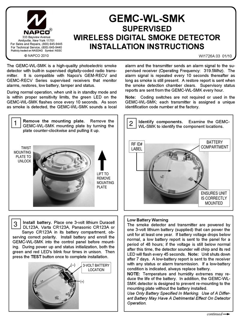
NAPCO GEMC-WL-SMK User manual

NAPCO

NAPCO GEMC-WL-SMK User manual

NAPCO GEM-SM User manual

NAPCO

NAPCO GEM-SM User manual

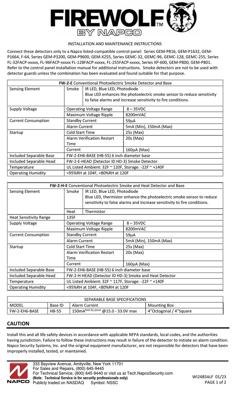
NAPCO FIREWOLF FW-2-E User manual

NAPCO

NAPCO FIREWOLF FW-2-E User manual

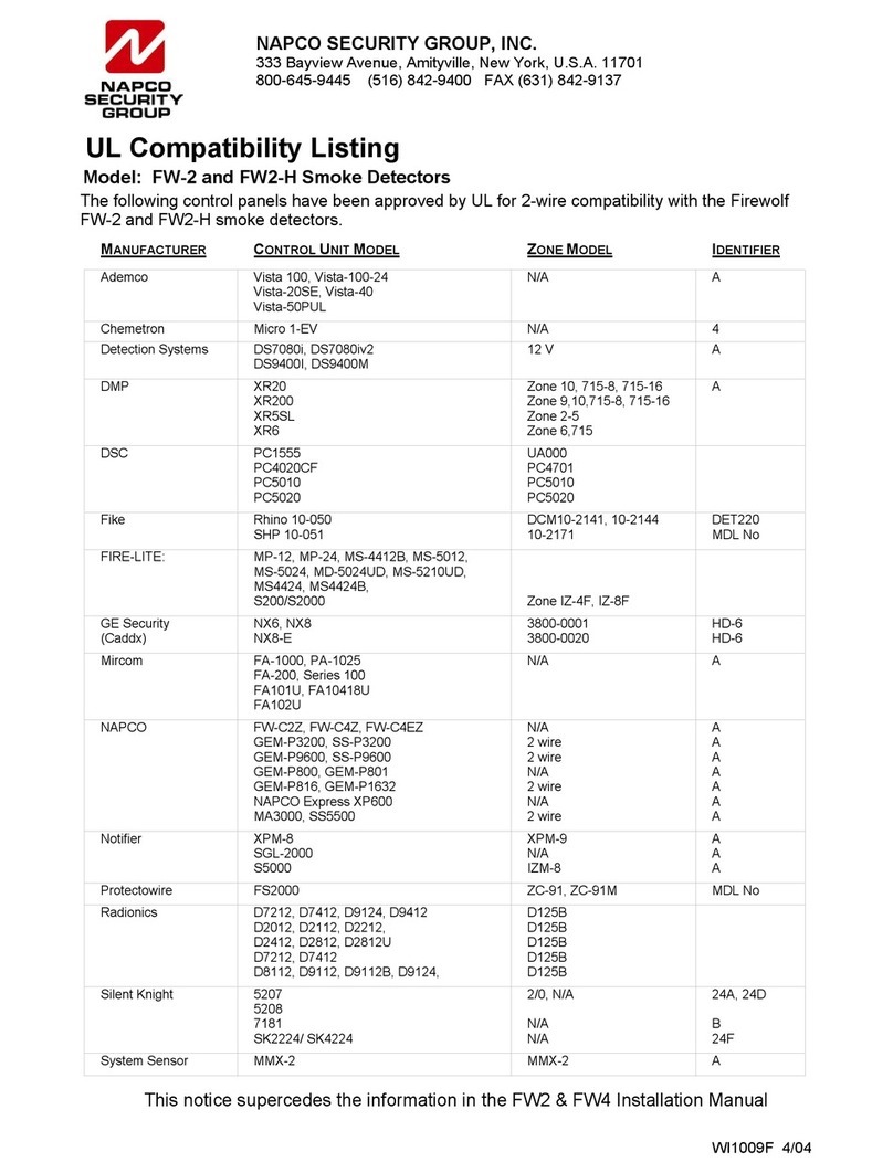
NAPCO FW-2 User manual

NAPCO

NAPCO FW-2 User manual

NAPCO GEM-SMK User manual

NAPCO

NAPCO GEM-SMK User manual

NAPCO FIREWOLF User manual

NAPCO

NAPCO FIREWOLF User manual

Popular Smoke Alarm manuals by other brands

Marmitek SD833 user manual

Marmitek

Marmitek SD833 user manual

System Sensor Innovair DH100LP quick start guide

System Sensor

System Sensor Innovair DH100LP quick start guide

ELRO FZ5010R instructions

ELRO

ELRO FZ5010R instructions

Teletek electronics SensoIRIS M140 IS manual

Teletek electronics

Teletek electronics SensoIRIS M140 IS manual

System Sensor ED-P Installation and maintenance instructions

System Sensor

System Sensor ED-P Installation and maintenance instructions

System Sensor 1400A Direct Wire Installation and maintenance instructions

System Sensor

System Sensor 1400A Direct Wire Installation and maintenance instructions

teko ASTRA ZITADEL quick start guide

teko

teko ASTRA ZITADEL quick start guide

Mavigard MG-400 Operating and maintenance manual

Mavigard

Mavigard MG-400 Operating and maintenance manual

Kidde 0918LL user guide

Kidde

Kidde 0918LL user guide

NOZE GS529 user manual

NOZE

NOZE GS529 user manual

Kidde KN-COSM-B user guide

Kidde

Kidde KN-COSM-B user guide

Panasonic EBL128 Daily user's manual

Panasonic

Panasonic EBL128 Daily user's manual

Profile PSE 504 manual

Profile

Profile PSE 504 manual

Kidde PI9000 user guide

Kidde

Kidde PI9000 user guide

HomeMatic HM-Sec-SD Mounting instruction and operating manual

HomeMatic

HomeMatic HM-Sec-SD Mounting instruction and operating manual

Regin SDD-S65-RACM Instruction

Regin

Regin SDD-S65-RACM Instruction

SimpliSafe CA002 owner's manual

SimpliSafe

SimpliSafe CA002 owner's manual

Satel TSD-1 manual

Satel

Satel TSD-1 manual

manuals.online logo
manuals.online logoBrands
  • About & Mission
  • Contact us
  • Privacy Policy
  • Terms and Conditions

Copyright 2025 Manuals.Online. All Rights Reserved.