Satel ASD-150 User manual

ASD-150
WIRELESS SMOKE DETECTOR
asd-150_en 02/17
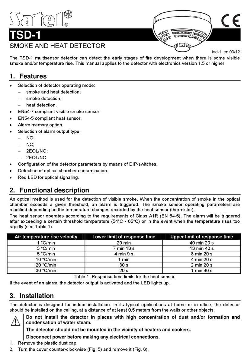
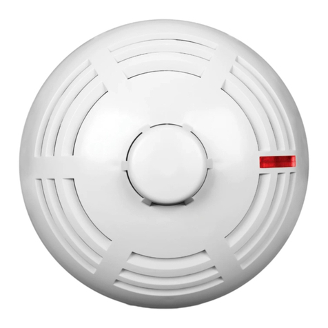
The ASD-150 detector can detect the early stages of fire development when there is some visible smoke. It can
operate as a stand-alone device or as part of the ABAX two-way wireless system. This manual applies to the
detector with electronics version 1.1 and with firmware version 1.0, which is supported by:
ACU-120 / ACU-270 controller with firmware version 5.02 (or newer),
ARU-100 repeater with firmware version 2.02 (or newer),
INTEGRA 128-WRL control panel with firmware version 1.15 (or newer).
Rating plate of the device can be found on the enclosure base.
1. Features
EN 14604 compliant visible smoke sensor.
Detection of optical chamber fouling.
Red LED for optical signaling.
Built-in sounder.
Test feature.
Tamper switch (supervised when working in the ABAX system).
Battery status control.
2. Functional description
Smoke detection
An optical method is used for the detection of visible smoke. When the concentration of smoke in the optical
chamber exceeds a given threshold, an alarm is triggered. The detector automatically compensates for gradual
changes in the optical chamber caused by deposition of dust.
Alarm signaling
The alarm is indicated visually (LED steady light) and acoustically (intermittent sound) for 5 minutes. Pressing
the test / reset button (designated with the letter A in Figure 2) during the alarm will clear the alarm condition
and will block the smoke detection function in the detector for 5 minutes.
Operation as part of the ABAX system
Information about alarm is sent by radio to the ACU-120 / ACU-270 controller / INTEGRA 128-WRL control
panel. After the causes of alarm have ceased to exist, information about alarm end will be sent.
Note: The detector can signal alarm detected by another detector registered in the same controller or in the
same INTEGRA 128-WRL control panel. For detailed information about this option, please refer to the
ACU-120 / ACU-270 controller manual or the control panel manual.
After starting the test mode in the ABAX system, the LED indicates as follows:
polling – short flash (80 milliseconds). If the optical chamber is soiled – two short flashes.
alarm memory – flashing rapidly.
Note: The alarm memory is cleared after exiting the test mode.
3. Installation
The detector is designed for indoor operation. For typical home and/or office applications, the detectors should
be installed on the ceiling, at a distance of minimum 0.5 meter from the wall or other objects.
Do not install the detector in places with high concentration of dust and/or formation and
condensation of water steam. The detector should not be mounted in the vicinity of heaters and
cookers.
The detector enclosure can not be closed without the battery inserted.

2 ASD-150 SATEL
Do not install the battery if the sounder is disconnected.
There is a danger of battery explosion when using a different battery than recommended by the
manufacturer, or handling the battery improperly.
Be particularly careful during installation and replacement of the battery. The manufacturer is
not liable for the consequences of incorrect installation of the battery.
1. Remove the plastic dust cap.
2. Turn the cover counter-clockwise (Fig. 2) and remove it (Fig. 3).
3. If the detector is to work as a stand-alone device, remove the jumper (designated by letter B on Fig. 4) from
the pins situated on the electronics board and skip the steps 5-8.
Note: After the battery is installed, removing / placing the jumper will have no effect on the detector operation.
4. Install the battery.
5. Add the detector to the wireless system (see the ACU-120 / ACU-270 controller manual, installer manuals
for INTEGRA 128-WRL or VERSA control panels).
6. Close the enclosure and temporarily fasten the detector at the future installation place.
7. Check the level of signal received from the detector by the ABAX controller or the INTEGRA 128-WRL
control panel. If the signal level is lower than 40%, select another place for installation. Sometimes, it is
sufficient to shift the device ten or twenty centimeters to obtain a considerable improvement in the signal
quality.
8. Open the enclosure.
9. Using wall plugs (screw anchors) and screws, secure the enclosure base to the wall. The wall plugs (screw
anchors) and screws delivered with the detector are intended for brick, concrete and similar mounting
surfaces. For other surfaces (e.g. drywall, wood, styrofoam), use other wall plugs (screw anchors), as
required.
10. Close the detector enclosure.
11. Press and hold down the test / reset button (designated with the letter A in Figure 2). Alarm should be
triggered after a few seconds.
12. If any other operations which may cause contamination of the optical chamber are being carried in the
facility where the detector is installed, the detector must be temporarily covered with a plastic dust cap.
4. Maintenance
The detectors should be subject to regular checks to ensure they are working correctly. Periodic checks should
be conducted at least every six months. To check whether the detector works, press and hold down the test /
reset button (designated with the letter A in Figure 2). Alarm should be triggered after a few seconds.
Cleaning the optical chamber
The detector is monitoring the state of the optical chamber. Deposition of dust in it may lead to malfunctioning of
the device. It is recommended that you have the optical chamber cleaned at least once a year. Cleaning the
chamber is necessary when the LED indicates fouling of the chamber (operation as part of the ABAX system –
2 short flashes during polling; stand-alone mode – 2 flashes every 30 seconds).
1. If the detector is used in the ABAX system, start the service mode in the control panel.
2. Remove the screw fastening the cover (Fig. 1).
3. Turn the cover counter-clockwise (Fig. 2) and remove it (Fig. 3).
4. Remove the battery.
5. Disconnect the plug (designated by letter A in Fig. 4) connecting the sounder wires with the electronics
board.
6. Push outward the catches (Fig. 5) and take out the electronics board with the optical chamber (Fig. 6).
7. Push outward the catch securing the optical chamber cover (Fig. 7) and remove it (Fig. 8).
8. Using a soft brush or compressed air, clean the labyrinth in the cover, as well as the base of the optical
chamber, paying attention to the recesses where LEDs are installed.
9. Replace the cover of the optical chamber.
10. Lay the sounder wires in their corresponding grooves.
11. Secure the electronics board with the optical chamber in the cover mounting catches. The board must be
mounted so that the LED coincides with the light guide.
12. Reconnect the plug connecting the sounder wires with the electronics board.
13. Re-install the battery.
14. Close the detector enclosure.

SATEL ASD-150 3
15. Press and hold down the test / reset button (designated with the letter A in Figure 2). Alarm should be
triggered after a few seconds.
5. Battery replacement
The used batteries must not be discarded, but should be disposed of in accordance with the
existing rules for environment protection.
The detector power supply battery (CR123A 3 V) ensures operation for about 2 years. If the detector is used as
part of the ABAX system, low battery information (voltage drop down to 2.75 V) is sent to the ACU-120 / ACU-
270 controller / INTEGRA 128-WRL control panel. If the detector is working in the stand-alone mode, the
information is presented optically and acoustically – 3 short LED flashes and 3 short sounds every 30 seconds.
1. If the detector is used in the ABAX system, start the service mode in the control panel.
2. Remove the screw fastening the cover (Fig. 1).
3. Turn the cover counter-clockwise (Fig. 2) and remove it (Fig. 3).

4 ASD-150 SATEL
4. Remove the discharged battery and dispose of in accordance with applicable environmental regulations.
5. Install a new CR123A 3 V lithium battery.
6. Close the detector enclosure.
7. Press and hold down the test / reset button (designated with the letter A in Figure 2). Alarm should be
triggered after a few seconds.
6. Specifications
Operating frequency band ..................................................................................................868.0 MHz ÷ 868.6 MHz
Radio communication range ........................................................................................... up to 500 m (in open area)
Power supply ................................................................................................................. lithium battery CR123A 3 V
Battery life expectancy..........................................................................................................................up to 2 years
Standby current consumption .......................................................................................................................... 85 µA
Maximum current consumption..................................................................................................................... 120 mA
Operating temperature range ................................................................................................................ 0 °C...55 °C
Dimensions .........................................................................................................................................ø108 x 54 mm
Weight...............................................................................................................................................................170 g
The ASD-150 wireless smoke detector conforms to the essential requirements of the EU Regulations and
Directives:
CPR 305/2011 Regulation of the European Parliament and of the Council of 9 March 2011 laying down
harmonized conditions for the marketing of construction products and repealing the Council Directive
89/106/EEC on construction products;
EMC 2004/108/EC Electromagnetic Compatibility Directive;
R&TTE Directive 1999/5/EC of the European Parliament and of the Council of 9 March 1999 on radio
equipment and terminal telecommunications equipment and the mutual recognition of their conformity;
The CNBOP-PIB Certification Body in Józefów issued the Certificate of Constancy of Performance 1438-CPR-
0490 for the construction product ASD-150 Wireless Smoke Detector, confirming its compliance with the
requirements of EN 54-5: 2003.
The National Institute of Telecommunications in Warsaw, as the Certification Body, issued the Confirmation of
Conformity No. 047/2015 for the ASD-150 Wireless Smoke Detector to confirm its compliance with the essential
requirements of the R&TTE Directive 1999/5/EC.
The CNBOP-PIB Certification Body in Józefów has tested the AS-150 Wireless Smoke Detector confirming its
compliance with the EN 14604 Standard, within the scope of Appendix L (approved for the use in caravans and
camper vans).
The Certificate and the Declaration of Performance can be downloaded from the www.satel.eu. website
SATEL Sp. z o.o. • ul. Budowlanych 66 • 80-298 Gdańsk • POLAND
16
1438-CPD-0490
EN 14604
ASD-150 Wireless Smoke Detector, stand-alone, capable of interacting over the air with the
intruder alarm system, based on scattered light principle, designed for indoor use.
Application – fire safety.
Technical specifications – please refer to this manual.
SATEL sp. z o.o. • ul. Budowlanych 66 • 80-298 Gdańsk • POLAND
tel. +48 58 320 94 00
www.satel.eu
Table of contents
Other Satel Smoke Alarm manuals
Popular Smoke Alarm manuals by other brands

Fenwal
Fenwal F1H-Q-RYW1K Operation & instruction manual

Nice
Nice FGSD-002 Instructions and warnings for installation and use

System Sensor
System Sensor Innovair DH100ACDCLWP Installation and maintenance instructions

First Alert
First Alert 7020b user manual

AngelEye
AngelEye SA700-AE-UK user manual

ZyXEL Communications
ZyXEL Communications SHD1115 manual