fireStorm SEQ18 User manual

FIRESTORM
SEQ18 / SEQ36
USER GUIDE

1 of 13
CONTENTS
Specification.............................................................................................................2
Description ..............................................................................................................2
Operating Modes.......................................................................................................3
Equal Mode ...........................................................................................................3
Example 1 ..........................................................................................................3
Example 2 ..........................................................................................................3
Settings Table .....................................................................................................4
Different Mode .......................................................................................................4
Example 1 ..........................................................................................................4
Example 2 ..........................................................................................................4
Clock Mode............................................................................................................5
Example 1 ..........................................................................................................5
Example 2 ..........................................................................................................5
Example 3 ..........................................................................................................5
Step Mode.............................................................................................................6
Burst Mode............................................................................................................6
Setup ...................................................................................................................7
Memory ................................................................................................................7
General Operation .....................................................................................................8
Controls................................................................................................................8
Menu....................................................................................................................8
Method of operation................................................................................................9
TIPS.....................................................................................................................9
Trigger Input ....................................................................................................... 10
Fire Button Trigger............................................................................................. 10
Current Trigger ................................................................................................. 10
Contact Closure Trigger (optional with Deadman Switch).......................................... 10
Trigger Output ..................................................................................................... 11
Battery Charge .................................................................................................... 12
Self Test Error Codes ............................................................................................ 12

2 of 13
SPECIFICATION
Power
2 x 12V SLA battery
Charger
110 / 230V charger UK : EU : USA
Output Current
6A peak per channel, max of 6A per block of 18 channels.
Output Voltage
24V
Timing Resolution
10ms
Max time between
Channels
9m59.99s
Channels
SEQ18 = 18 | SEQ36 = 36
Trigger Input
1.5V - >24V or Contact Closure
Trigger Threshold Current
<25mA = No Trigger. >35mA Guaranteed Trigger.
Operating Modes
Equal : Different : Clock : Step : Burst
DESCRIPTION
The FireStorm SEQ18 / SEQ36 are highly flexible pyrotechnic, firework and SFX sequencers.
They are intended for the safe and reliable ignition of pyrotechnics and control of solenoid
valves and other SFX equipment.
Each sequencer allows time delays and pulse durations to be easily setup in various ways.
Please familiarise yourself with the operation of the units before use, and adhere to all
industry best practices.
3 of 13
OPERATING MODES
The sequencer has 5 operating modes.
Equal : Different : Clock : Step : Burst
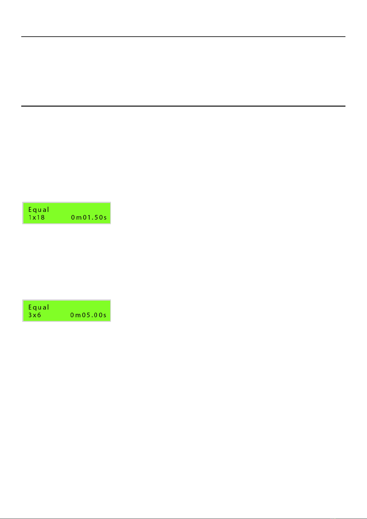
EQUAL MODE
Equal Mode sets the same interval between all channels.
The channels can be fired in groups. Each successive Trigger Input will fire the next group of
channels. After all channels are fired the Trigger Output will fire on each successive Trigger
Input pulse. This is to enable linking multiple sequencers for longer sequences.
Example 1
[1 Group of 18 Channels]
Channel 1 - 18 will fire with 1.5 seconds between each channel when the 1st Trigger Input is
received.
Trigger Output will then fire on each successive Trigger Input.
Example 2
[3 Groups of 6 Channels]
Channel 1 - 6 will fire with 5 seconds between each channel when the 1st Trigger Input is
received.
Channel 7 - 12 will fire with 5 seconds between each channel when the 2nd Trigger Input is
received.
Channel 13 - 18 will fire with 5 seconds between each channel when the 3rd Trigger Input is
received.
Trigger Output will then fire on each successive Trigger Input.
4 of 13
Settings Table
SETTING
TRIGGER #
RESULT
ALL
1st
Channel 01 - 18 including Trigger Out
1x18
1st
Channel 01 –18, then Trigger Out.
2x9
1st
Channel 01 - 09
2nd
Channel 10 –18, then Trigger Out.
3x6
1st
Channel 01 - 06
2nd
Channel 07 - 12
3rd
Channel 13 –18, then Trigger Out.
6x3
1st
Channel 01 - 03
2nd
Channel 04 - 06
3rd
Channel 07 - 09
4th
Channel 10 - 12
5th
Channel 13 - 15
6th
Channel 16 –18, then Trigger Out.
9x2
1st
Channel 01 - 02
2nd
Channel 03 - 04
3rd
Channel 05 - 06
4th
Channel 07 - 08
5th
Channel 09 - 10
6th
Channel 11 - 12
7th
Channel 13 - 14
8th
Channel 15 - 16
9th
Channel 17 –18, then Trigger Out.
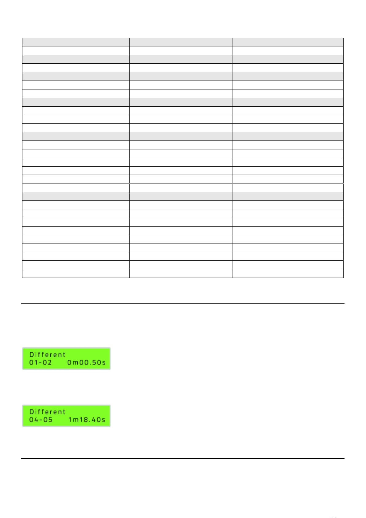
DIFFERENT MODE
Different Mode sets the interval between channels relative to the last channel.
Example 1
Channel 2 will fire 0.5 seconds after Channel 1.
Example 2
Channel 5 will fire 1 minute 18.40 seconds after Channel 4.
5 of 13
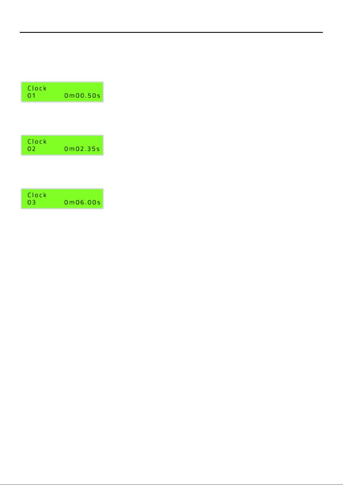
CLOCK MODE
Clock Mode sets the absolute time a Channel will fire, relative to a clock that starts when
the first Trigger Input is received.
Example 1
Channel 1 will fire 0.5 seconds after the Trigger Input is received.
Example 2
Channel 2 will fire 2.35 seconds after the Trigger Input is received.
Example 3
Channel 3 will fire 6 seconds after the Trigger Input is received.
Note: Channels do not have to fire in order. For example, Channel 2 could fire at 0m05:00
and Channel 1 could fire at 0m02:00.
Note: Channels that have identical times will fire together. For example, if Channel 1 and
Channel 4 are both set to 0m05:00 they will both fire 5 seconds after the Trigger Input is
received.

6 of 13
STEP MODE
Step Mode will step to the next channel on each successive Trigger Input received. No timing
setup is required. Once all channels are fired the Trigger Output will pulse on each successive
Trigger Input. This allows multiple sequencers to be connected together for longer sequences.
BURST MODE
Burst Mode will fire a user selected group of channels with an equal time delay between each
channel in a group, on each successive Trigger Input. It is similar to Equal Mode, but allows
greater flexibility in programming which channels to fire.
TRIGGER
START
CHANNEL
END
CHANNEL
DELAY
DESCRIPTION
T01
01
12
0.05s
The 1st trigger pulse fires channel 1 to 12
with 0.05 seconds between channels.
T02
13
14
2.00s
The 2nd trigger pulse fires channel 13 to 14
with 2.00 seconds between channels.
T03
15
19
1.55s
The 3rd trigger pulse fires channel 15 to 19
with 1.55 seconds between channels.
…
…
…
…
…
…
…
…
…
…
T18
32
36
0.75s
The 18th trigger pulse fires channel 32 to 36
with 0.75 seconds between channels.
Example 1
[Trigger Number] [Start Channel] - [End Channel] [Delay]
Channel 1 to 2 will fire with 0.5 seconds delay between them when the first Trigger Input is
received.
Example 2
[Trigger Number] [Start Channel] [End Channel] [Delay]
Channel 10 to 15 will fire with 1.50 seconds delay between them when the second Trigger
Input is received.
7 of 13
SETUP
Various options can be selected in the setup menu.
SETTING
Pulse
Independently set how long each channel fires for, range 0.01 - 9.99 seconds.
Language
English : Spanish : German : Italian : French
Reset
Reset all settings to default.
MEMORY
An entire series of delays can be saved in each mode. This allows commonly used sequences
to be stored for future use.
Note: The sequencer will automatically store the current setup. If the sequencer is powered
off and on it will retain the current settings.
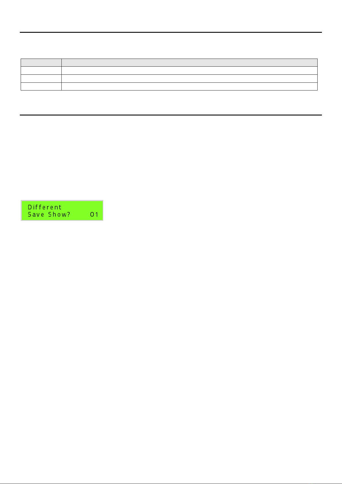
At the end of each menu there is the option to save the show in 1 of 3 possible memory
locations. If a sequence is already saved in a memory location, it will be displayed with an *
next to the location. It can be overwritten if required.

8 of 13
GENERAL OPERATION
CONTROLS
BUTTON
Menu
Press to return to the main menu / go back.
Run
Simulate the current settings on the LEDs. The channels will not fire. This is
useful for visualizing the current settings.
Test
Press and hold to check continuity on all channels.
Fire
Only operational when sequencer is ARMED. Press to Trigger the sequencer
if no external Trigger is used.
Rotary Knob
Rotate to increase / decrease selected digit. Press for OK.
Key Switch
Power OFF / ON / ARM.
MENU
MENU ITEM
1] Equal (ALL, 1x18, 2x9, 3x6,
9x2 etc)
Set an equal time interval between all channels. Channels
may be split into preset groups.
2] Different
Set relative interval between channels.
2.1] Setup
Setup a series of intervals.
2.2] Load Show
Load a stored series of intervals.
2.3] Clear Show
Clear a stored series of intervals.
3] Clock
Set absolute time channel will fire.
3.1] Setup
Setup a series of times.
3.2] Load Show
Load a stored series of times.
3.3] Clear Show
Clear a stored series of times.
4] Step
Step to the next channel on each Trigger Input.
5] Burst
Set varying time intervals between user designated
groups.
3.1] Setup
Setup a series of intervals.
3.2] Load Show
Load a stored series of intervals.
3.3] Clear Show
Clear a stored series of intervals.
6] Setup
Device configuration options.
6.1] Pulse
Set the duration of the firing pulse per channel.
6.2] Language
Set menu language.
6.3] Reset
Restore factory defaults.

9 of 13
METHOD OF OPERATION
Note: We recommend minimising the amount of time the unit is switched on when
pyrotechnics are connected. This minimises the chance of an accidental firing.
1. Set key to ON. Ensure unit passes self test.
2. Set mode using rotary knob.
3. Set intervals using rotary knob.
4. Press PLAY button to run the sequence on LEDs. No channels will be fired.
5. When satisfied sequence is correct, carefully connect igniters to terminals.
ENSURE AREA IS CLEAR AND SAFE FOR CONTINUITY CHECK!
6. Press TEST to check channel continuity on LEDs.
7. Set key to ARM.
UNIT IS NOW DANGEROUS AND READY TO FIRE.
8. Press FIRE button or provide external Trigger Input to start the sequencer.
TIPS
1. Do not fire many cues at the same time / overlapping cues. The total current available
is limited to about 4 Amps per block of 18
channels to protect the internal circuitry. To
fire many channels at once we recommend
setting a very small delay between channels,
e.g. 10ms. This will be almost imperceptible
to the human eye but will allow each effect to
be fired individually. Pyro igniters normally
burn out open circuit under 5ms. Ideally
solenoids should not overlap. However for low
current solenoids it will be possible to overlap
several.
2. Remove igniter wires carefully by pressing
both terminals down together and removing
the wires. Grabbing a bunch of wires and
pulling them out roughly may damage the
connections. Spare user replaceable terminal
strips are available should this happen.
3. Wires can be connected neatly and securely
by wrapping each leg around the terminals as
shown opposite.

10 of 13
TRIGGER INPUT
The sequencer is very flexible and may be triggered in several ways.
The Trigger Input LED will light whenever an external trigger is sensed. This is useful
for setup and testing.
The sequencer will only fire channels when key is in the ARM position. The ARM LED
will be on whenever the key is in ARM position.
Fire Button Trigger
The sequencer can be triggered by pressing the FIRE button on the front panel.
Current Trigger
Current from an external firing system or our dedicated trigger unit can trigger the
sequencer. By default, the Trigger Input terminals are connected to the Current Mode input
on the circuit board.
Contact Closure Trigger (optional with Deadman Switch)
A Contact Closure input connector can be fitted. This allows the optional Deadman Switch to
be used or any other contact closure input. Please contact us for more information.

11 of 13
TRIGGER OUTPUT
The Trigger Output terminals can be used to connect the sequencer to another sequencer.
Several units can be chained for more shots. When operating in EQUAL and STEP mode the
Trigger Input pulses will be passed through to the second sequencer and so on.
The Trigger Output LED will light whenever there is a Trigger Output pulse.
Example 1
3 x 18 shot sequencers all in STEP mode require 3 x 18 = 54 Trigger Input pulses to fire all
channels.
Example 2
2 x 18 shot sequencers all in EQUAL [1x18] mode would require 2 x 18 = 36 Trigger Input
pulses to fire all channels
Example 3
3 x 18 shot sequencers all in EQUAL [3x6] mode would require 3 x 3 = 9 Trigger Input
pulses to fire all channels.

12 of 13
BATTERY CHARGE
The sequencer has 2 x 12V lead acid batteries installed.
Only use the supplied smart charger to charge the batteries.
The charge port should not be used to power the device directly.
The battery charger LED will flash orange when charging and steady green when battery is
full.
The unit may be switched on while charging. However, it is recommended to keep the unit
switched off to avoid false ‘end of charge’ detection.
We recommend to keep the batteries in good condition by avoiding very low discharge.
The battery voltage and firmware version are displayed on startup.
Note: Charge the battery every 3 months even if sequencer has not been used.
Note: The battery voltage should be above 23V for best operation.
SELF TEST ERROR CODES
The sequencer runs a self test on start up.
This may warn you of defects by displaying an error code.
Pressing OK will move past this error and allow operation of the sequencer.
PROCEED WITH CAUTION WHEN AN ERROR CODE IS SHOWN.
ERROR #
DESCRIPTION
ERROR 01
ARM MOSFET stuck ON.
Sequencer will not be operational. Do not use.
Contact manufacturer for repair.
ERROR 02
Any channel MOSFET stuck ON. Bank with problem channel will flash.
Press OK to proceed.
Be aware that a channel(s) are PERMANENTLY ON and could fire as
soon as an igniter is connected. PROCEED WITH CAUTION.
Contact manufacturer for repair.
ERROR 03
Any channel MOSFET stuck OFF. Channel LED will flash.
Press OK to proceed.
Be aware that channel(s) are permanently off and may not function.
Contact manufacturer for repair.

13 of 13
This manual suits for next models
1
Table of contents
Other fireStorm Recording Equipment manuals

Popular Recording Equipment manuals by other brands


MicroBoards Technology
MicroBoards Technology CopyWriter Live CWL-6200 instruction manual

Peecker Sound
Peecker Sound AMCL2 instruction manual

Enforcement Technology Group
Enforcement Technology Group 60113 operating manual

DIGISYNTHETIC
DIGISYNTHETIC Pro series Operating instruction

Klang
Klang AM-08XI quick start guide

DSPPA
DSPPA PC1010P owner's manual


