Fireye MB485ETH-CG Owner's manual

© 2020 Carrier 1
CG-1001
November 23, 2020
MB485ETH-CG
Communication Gateway
Installation and Operation
1DESCRIPTION
The MB485ETH-CG communication gateway is an
accessory designed to allow any Modbus-capable
Fireye control to communicate to a building
management system or PLC using the BACnet/IP,
BACnet MS/TP, EtherNet/IP or Modbus TCP/IP
protocols. Multiple devices can be connected to a single
communication gateway. Configuration is done using
any web browser connected to the same network as the
communication gateway, or wirelessly via the built-in
access point.
Additionally, the communication gateway provides
remote monitoring capabilities through the cloud using
SMC Cloud services.

2 © 2020 Carrier
Technical Support
Thank you for purchasing the MB485ETH-CG.
Please call Fireye for technical support of this product. Please note that the manufacturer (MSA Safety
dba Sierra Monitor) does not provide direct support for this Fireye-branded product.
Support Contact Information:
Fireye, Inc.
3 Manchester Road
Derry, NH 03038
Customer Service:
603-432-4100
For online support fill in and submit the form found at: https://www.fireye.com/Home/ContactUs.
Website: www.fireye.com

© 2020 Carrier 3
Quick Start Guide
1. Record the information about the unit. (Section 4.1)
2. Check that the MB485ETH-CG and customer device COM settings match. (Section 4.3)
3. Connect the MB485ETH-CG 3 pin RS-485 R1 port to the RS-485 network connected to each of the
devices. (Section 5.1)
4. If using a serial field protocol:
Connect the MB485ETH-CG 3 pin RS-485 R2 port to the field protocol cabling. (Section 5.2)
5. Connect power to the MB485ETH-CG 3 pin power port. (Section 5.5)
6. Connect a PC to the MB485ETH-CG via Ethernet cable or by the MB485ETH-CG’s Wi-Fi Access
Point. (Section 6)
7. Setup Web Server Security and login via web browser. (Section 7)
8. Configure the MB485ETH-CG to connect to the local network. (Section 8)
9. Integrate the MB485ETH-CG with SMC Cloud or opt out. (Section 9)
10. Use a web browser to access the MB485ETH-CG Web Configurator page to select the profile of the
device attached to the MB485ETH-CG and enter any necessary device information. Once the device
is selected, the MB485ETH-CG automatically builds and loads the appropriate configuration.
(Section 10.3)

4 © 2020 Carrier
TABLE OF CONTENTS
1DESCRIPTION........................................................................................................................................... 1
2Certification .......................................................................................................................................... 8
2.1 BTL Mark – BACnet®Testing Laboratory....................................................................................... 8
3Introduction .......................................................................................................................................... 9
3.1 MB485ETH-CG Gateway ............................................................................................................... 9
3.2 Methods of Configuration ............................................................................................................. 10
4MB485ETH-CG Setup ........................................................................................................................ 11
4.1 Record Identification Data ............................................................................................................ 11
4.2 Point Count Capacity.................................................................................................................... 11
4.3 Configuring Device Communications ........................................................................................... 12
4.3.1 Confirm the Device and MB485ETH-CG COM Settings Match.............................................. 12
4.3.2 Set Node-ID for Any Device Attached to the MB485ETH-CG ................................................ 12
4.3.3 Set IP Address for Any Ethernet Device Connected to the MB485ETH-CG .......................... 12
4.4 Attaching the Antenna .................................................................................................................. 12
5Interfacing MB485ETH-CG to Devices............................................................................................. 13
5.1 Device Connections to MB485ETH-CG ....................................................................................... 13
5.2 Wiring Field Port to RS-485 Serial Network ................................................................................. 13
5.3 Bias Resistors............................................................................................................................... 14
5.4 Termination Resistor..................................................................................................................... 15
5.5 Power-Up MB485ETH-CG ........................................................................................................... 16
6Connect to the MB485ETH-CG ......................................................................................................... 17
6.1 Connect the PC to the MB485ETH-CG........................................................................................ 17
6.1.1 Connecting to the MB485ETH-CG via Ethernet ..................................................................... 17
6.1.1.1 Changing the Subnet of the Connected PC.................................................................... 17
6.1.1.2 Connecting to the MB485ETH-CG Over Wi-Fi Access Point ......................................... 18
7Setup Web Server Security............................................................................................................... 19
7.1 Login to the MB485ETH-CG......................................................................................................... 19
7.2 Select the Security Mode.............................................................................................................. 21
7.2.1HTTPS with Own Trusted TLS Certificate .............................................................................. 22
7.2.2 HTTPS with Default Untrusted Self-Signed TLS Certificate or HTTP with Built-in Payload
Encryption ............................................................................................................................................ 22
8Configure Network Settings ............................................................................................................. 23
8.1 Navigate to the Network Settings ................................................................................................. 23
8.2 Change the MB485ETH-CG IP Address ...................................................................................... 24
8.2.1 Common Settings.................................................................................................................... 24
8.2.2 Wired Network Settings........................................................................................................... 25
8.2.3Wi-Fi Client Settings................................................................................................................ 26
8.2.4 Wi-Fi Access Point Settings .................................................................................................... 27
9SMC Cloud User Setup, Registration and Login ............................................................................ 28
9.1 Choose Whether to Integrate SMC Cloud.................................................................................... 28
9.2 User Setup.................................................................................................................................... 30
9.3 Registration Process .................................................................................................................... 32
9.4 Login to SMC Cloud ..................................................................................................................... 36
10 Configure the MB485ETH-CG ....................................................................................................... 38
10.1 Navigate to the MB485ETH-CG Web Configurator ................................................................ 38
10.2 Select Field Protocol and Set Configuration Parameters ....................................................... 39
10.3 Setting MB485ETH-CG Active Profiles................................................................................... 40
10.4 Verify Device Communications ............................................................................................... 41
10.5 BACnet: Setting Node_Offset to Assign Specific Device Instances ....................................... 42

© 2020 Carrier 5
10.6 How to Start the Installation Over: Clearing Profiles............................................................... 43
Appendix A Troubleshooting................................................................................................................... 44
Appendix A.1 Lost or Incorrect IP Address ............................................................................................. 44
Appendix A.2 Viewing Diagnostic Information ........................................................................................ 45
Appendix A.3 Checking Wiring and Settings........................................................................................... 46
Appendix A.4 LED Diagnostics for Communications Between MB485ETH-CG and Devices................ 47
Appendix A.5 Taking a MB485ETH-CG Diagnostic Capture .................................................................. 48
Appendix A.5.1 Taking a Capture with Older Firmware ...................................................................... 49
Appendix A.6 Wi-Fi Signal Strength ........................................................................................................ 51
Appendix A.7 Factory Reset Instructions ................................................................................................ 51
Appendix A.8 Internet Browser Software Support................................................................................... 51
Appendix B Additional Information......................................................................................................... 52
Appendix B.1 Updating Firmware............................................................................................................ 52
Appendix B.2 BACnet: Setting Network_Number for More Than One MB485ETH-CG on the Subnet.. 52
Appendix B.3 Mounting ........................................................................................................................... 53
Appendix B.4 Physical Dimension Drawing ............................................................................................ 54
Appendix B.5 Change Web Server Security Settings After Initial Setup................................................. 55
Appendix B.5.1 Change Security Mode............................................................................................... 56
Appendix B.5.2 Edit the Certificate Loaded onto the MB485ETH-CG ................................................ 57
Appendix B.6 Change User Management Settings................................................................................. 58
Appendix B.6.1 User Management...................................................................................................... 58
Appendix B.6.1.1 Create Users........................................................................................................ 59
Appendix B.6.2 Edit Users................................................................................................................... 60
Appendix B.6.2.1 Delete Users ........................................................................................................ 61
Appendix B.6.3 Change MB485ETH-CG Password............................................................................ 62
Appendix B.7 SMC Cloud Connection Warning Message ...................................................................... 63
Appendix B.8 System Status Button ....................................................................................................... 64
Appendix C Reference.............................................................................................................................. 65
Appendix C.1 Specifications.................................................................................................................... 65
Appendix C.1.1 Compliance with UL Regulations ............................................................................... 65
Appendix D Device Mapping.................................................................................................................... 66
Appendix D.1 YB110_FSG Modbus RTU Mappings to Field Protocols.................................................. 67
Appendix D.2 PPC4000_NXF4000 Modbus RTU Mappings to Field Protocols ..................................... 69
Appendix D.3 ZB110_FSG Modbus RTU Mappings to Field Protocols.................................................. 72
Appendix D.4 PPC6000_NX6100 Modbus RTU Mappings to Field Protocols ....................................... 75
Appendix D.5 E110 Modbus RTU Mappings to Field Protocols ............................................................. 82
Appendix D.6 MicroM Modbus RTU Mappings to Field Protocols .......................................................... 84
Appendix D.7 BurnerPRO_Gen_3 Modbus RTU Mappings to Field Protocols ...................................... 85
Appendix D.8 NXCES02 Modbus RTU Mappings to Field Protocols ..................................................... 87
Appendix D.9 FX_Series_Servos Modbus RTU Mappings to Field Protocols........................................ 88
Appendix D.10 ACS550 Modbus RTU Mappings to Field Protocols ...................................................... 90
Appendix D.11 Insight_Insight_II_Scanner Modbus RTU Mappings to Field Protocols ......................... 91
Appendix D.12 NXTSD507HD_NXTSD512HD Modbus TCP/IP Mappings to Field Protocols............... 95

6 © 2020 Carrier
LIST OF FIGURES
Figure 1: Method of Configuration for the Devices ..................................................................................... 10
Figure 2: MB485ETH-CG Part Numbers .................................................................................................... 11
Figure 3: Supported Point Count Capacity ................................................................................................. 11
Figure 4: Points per Device......................................................................................................................... 11
Figure 5: COM Settings............................................................................................................................... 12
Figure 6: RS-485 Connections from Devices to the MB485ETH-CG ......................................................... 13
Figure 7: Connection from MB485ETH-CG to RS-485 Field Network........................................................ 13
Figure 8: Bias Resistor DIP Switches ......................................................................................................... 14
Figure 9: Termination Resistor DIP Switch................................................................................................. 15
Figure 10: Required Current Draw for the MB485ETH-CG ........................................................................ 16
Figure 11: Power Connections.................................................................................................................... 16
Figure 12: Ethernet Port Location ............................................................................................................... 17
Figure 13: Web Server Security Unconfigured Window ............................................................................. 19
Figure 14: Connection Not Private Warning ............................................................................................... 19
Figure 15: Warning Expanded Text ............................................................................................................ 20
Figure 16: MB485ETH-CG Login................................................................................................................ 20
Figure 17: Security Mode Selection Screen................................................................................................ 21
Figure 18: Security Mode Selection Screen – Certificate & Private Key .................................................... 22
Figure 19: Web App Landing Page............................................................................................................. 23
Figure 20: Settings Tabs............................................................................................................................. 23
Figure 21: FS-GUI Landing Page ............................................................................................................... 23
Figure 22: Common Network Settings ........................................................................................................ 24
Figure 23: Ethernet Port Network Settings ................................................................................................. 25
Figure 24: Wi-Fi Client Network Settings .................................................................................................... 26
Figure 25: FS-GUI Wi-Fi AP Network Settings ........................................................................................... 27
Figure 26: Generic Web App Page – First Login ........................................................................................ 28
Figure 27: SMC Cloud Opt Out Warning Window ...................................................................................... 29
Figure 28: Welcome to SMC Cloud Email .................................................................................................. 30
Figure 29: Setting User Details ................................................................................................................... 31
Figure 30: SMC Cloud Registration Message............................................................................................. 32
Figure 31: SMC Cloud Registration – Installer Details ............................................................................... 33
Figure 32: SMC Cloud Registration – Site Details ...................................................................................... 33
Figure 33: SMC Cloud Registration – Gateway Details.............................................................................. 34
Figure 34: SMC Cloud Registration – SMC Cloud Account........................................................................ 34
Figure 35: Device Registered for SMC Cloud............................................................................................. 35
Figure 36: SMC Cloud Login Page ............................................................................................................. 36
Figure 37: SMC Cloud Privacy Policy ......................................................................................................... 36
Figure 38: SMC Cloud Landing Page ......................................................................................................... 37
Figure 39: Web App Landing Page............................................................................................................. 38
Figure 40: Configuration Tab ...................................................................................................................... 38
Figure 41: Web Configurator Showing Protocol Selector Parameter ......................................................... 39
Figure 42: Web Configurator Showing no Active Profiles........................................................................... 40
Figure 43: Profile Selection Menu............................................................................................................... 41
Figure 44: Web Configurator Showing Active Profile Additions.................................................................. 41
Figure 45: Web Configurator Node Offset Field ......................................................................................... 42
Figure 46: Active Profiles ............................................................................................................................ 42
Figure 47: Ethernet Port Location ............................................................................................................... 44
Figure 48: Error Messages Screen ............................................................................................................. 45
Figure 49: Diagnostic LEDs ........................................................................................................................ 47
Figure 50: Ethernet Port Location ............................................................................................................... 49
Figure 51: Wi-Fi Signal Strength Listing ..................................................................................................... 51
Figure 52: Web Configurator – Network Number Field............................................................................... 52
Figure 53: DIN Rail...................................................................................................................................... 53
Figure 54: MB485ETH-CG FPA-W44 Dimensions ..................................................................................... 54

© 2020 Carrier 7
Figure 55: FS-GUI Landing Screen ............................................................................................................ 55
Figure 56: FS-GUI Security Setup .............................................................................................................. 56
Figure 57: FS-GUI Security Setup – Certificate Loaded............................................................................. 57
Figure 58: FS-GUI User Management ........................................................................................................ 58
Figure 59: Create User Window.................................................................................................................. 59
Figure 60: Setup Users ............................................................................................................................... 60
Figure 61: Edit User Window ...................................................................................................................... 60
Figure 62: Setup Users ............................................................................................................................... 61
Figure 63: User Delete Warning ................................................................................................................. 61
Figure 64: MB485ETH-CG Password Update via FS-GUI ......................................................................... 62
Figure 65: SMC Cloud Connection Problems Message ............................................................................. 63
Figure 66: Specifications............................................................................................................................. 65

8 © 2020 Carrier
2CERTIFICATION
2.1 BTL Mark – BACnet® 1 Testing Laboratory
1BACnet is a registered trademark of ASHRAE
The BTL Mark on the MB485ETH-CG is a symbol that indicates that a product
has passed a series of rigorous tests conducted by an independent laboratory
which verifies that the product correctly implements the BACnet features
claimed in the listing. The mark is a symbol of a high-quality BACnet product.
Go to www.BACnetInternational.net for more information about the BACnet
Testing Laboratory. Click here for the BACnet PIC Statement.

© 2020 Carrier 9
3INTRODUCTION
3.1 MB485ETH-CG Gateway
The MB485ETH-CG wireless gateway is an external, high performance building automation multi-
protocol gateway that is preconfigured to automatically communicate between Fireye’s devices (hereafter
simply called “device”) connected to the MB485ETH-CG and automatically configures them for BACnet/IP,
BACnet MS/TP, Modbus TCP/IP and EtherNet/IP.
It is not necessary to download any configuration files to support the required applications. The MB485ETH-
CG is pre-loaded with tested profiles/configurations for the supported devices.
Connectivity Diagram:
The MB485ETH-CG can connect with the SMC Cloud. The SMC Cloud allows technicians, the OEM's
support team and MSA Safety's support team to remotely connect to the MB485ETH-CG. The SMC Cloud
provides the following capabilities for any registered devices in the field:
•Remotely monitor and control devices.
•Collect device data and view it on the SMC Cloud Dashboard and the SMC Smart Phone App.
•Create user defined device notifications (alarm, trouble and warning) via SMS and/or Email.
•Generate diagnostic captures (as needed for troubleshooting) without going to the site.
For more information about the SMC Cloud, refer to the SMC Cloud Start-up Guide.
10 © 2020 Carrier
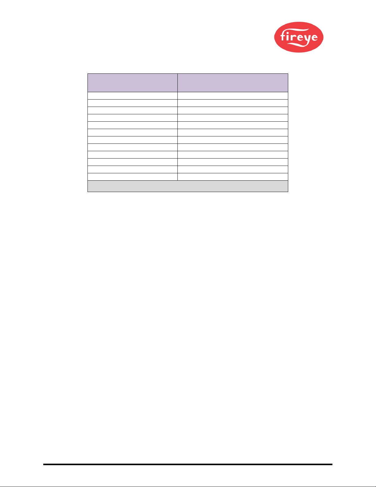
3.2 Methods of Configuration
Devices Communication Protocol
YB110_FSG
Modbus RTU
PPC4000_NXF4000
Modbus RTU
ZB110_FSG
Modbus RTU
PPC6000_NX6100
Modbus RTU
E110
Modbus RTU
MicroM
Modbus RTU
BurnerPRO_Gen_3
Modbus RTU
NXCESO2
Modbus RTU
FX_Series_Servos
Modbus RTU
ACS550
Modbus RTU
Insight_Insight_II_Scanner
Modbus RTU
NXTSD507HD_NXTSD512HD
Modbus TCP/IP
Figure 1: Method of Configuration for the Devices

© 2020 Carrier 11
4MB485ETH-CG SETUP
4.1 Record Identification Data
Each MB485ETH-CG has a unique part number located on the side or the back of the unit. This number
should be recorded, as it may be required for technical support. The numbers are as follows:
Model Part Number
MB485ETH-CG
FPA-W44-0042
Figure 2: MB485ETH-CG Part Numbers
•FPA-W44 units have the following 4 ports: Ethernet + Wi-Fi + RS-485 + RS-485/RS-232
4.2 Point Count Capacity
The total number of points presented to the device(s) attached to the MB485ETH-CG cannot exceed:
Part number Total Points
FPA-W44-0042
10,000
Figure 3: Supported Point Count Capacity
Devices Points Per Device
YB110_FSG
96
PPC4000_NXF4000
168
ZB110_FSG
163
PPC6000_NX6100
439
E110
77
MicroM
32
BurnerPRO_Gen_3
82
NXCESO2
42
FX_Series_Servos
71
ACS550
51
Insight_Insight_II_Scanner
245
NXTSD507HD_NXTSD512HD
306
Figure 4: Points per Device

12 © 2020 Carrier
4.3 Configuring Device Communications
4.3.1 Confirm the Device and MB485ETH-CG COM Settings Match
•Any connected serial device MUST have the same baud rate, data bits, stop bits, and
parity settings as the MB485ETH-CG.
•Figure 5 specifies the device serial port settings required to communicate with the MB485ETH-CG.
Port Setting NXCESO2 E110, Micro M Other Devices
Protocol Modbus RTU
Modbus RTU
Modbus RTU
Baud Rate 57600
4800
9600
Parity None
None
None
Data Bits 8
8
8
Stop Bits 1
1
1
Figure 5: COM Settings
4.3.2 Set Node-ID for Any Device Attached to the MB485ETH-CG
•Set Node-ID for the device attached to MB485ETH-CG. The Node-ID needs to be uniquely
assigned between 1 and 255.
•Document the Node-ID that is assigned. The Node-ID assigned is used for deriving the Device
Instance for BACnet/IP and BACnet MS/TP.(Section 10.5)
NOTE: The Modbus TCP/IP field protocol Node-IDs are automatically set to be the same value as
the Node-ID of the device.
4.3.3 Set IP Address for Any Ethernet Device Connected to the MB485ETH-CG
•Ensure the device is set to Modbus TCP/IP to communicate with the MB485ETH-CG.
•The device needs to be on the same IP subnet as the MB485ETH-CG and the configuration PC.
•Record the following device information to start the setup:
oIP Address
oIP port
oTCP_ID
NOTE: This information is required for Section 10.3.
4.4 Attaching the Antenna
Wi-Fi Antenna:
Screw in the Wi-Fi antenna to the front of the unit as shown in Figure 54.
NOTE: Using an external antenna is also an option. An external antenna can be plugged into the
SMA connector. The best antenna for the job depends on the range, topography and
obstacles between the two radios.

© 2020 Carrier 13
5INTERFACING MB485ETH-CG TO DEVICES
5.1 Device Connections to MB485ETH-CG
The MB485ETH-CG has a 3-pin Phoenix connector for connecting RS-485 devices on the R1 port. See
specific device bulletins for details on how to properly connect Modbus to each.
NOTE: Use standard grounding principles for RS-485 GND.
5.2 Wiring Field Port to RS-485 Serial Network
•Connect the RS-485 network wires to the 3-pin RS-485 connector on the R2 port. (Figure 7)
oUse standard grounding principles for RS-485 GND
•See Section 6 for information on connecting to an Ethernet network.
Device Pins
MB485ETH-
CG Pin
Label
Pin
Assignment
RS-485 +
TX+
RS-485 +
RS-485 -
RX-
RS-485 -
RS-485 GND
GND
RS-485 GND
BMS
Wiring
MB485ETH-
CG Pin
Label
Pin
Assignment
RS-485 +
+
RS-485 +
RS-485 -
-
RS-485 -
-
GND
RS-485 GND
Figure 7: Connection from MB485ETH-CG to RS-485 Field Network
G
-
+
Figure 6: RS-485 Connections from Devices to the MB485ETH-CG
G
-
+

14 © 2020 Carrier
5.3 Bias Resistors
To enable Bias Resistors, move both the BIAS- and BIAS+ dip switches to the right as shown in
Figure 8.
The MB485ETH-CG bias resistors are used to keep the RS-485 bus to a known state, when there is no
transmission on the line (bus is idling), to help prevent false bits of data from being detected. The bias
resistors typically pull one line high and the other low - far away from the decision point of the logic.
The bias resistor is 510 ohms which is in line with the BACnet spec. It should only be enabled at one
point on the bus (for example, on the field port were there are very weak bias resistors of 100k). Since
there are no jumpers, many gateways can be put on the network without running into the bias resistor
limit which is < 500 ohms.
NOTE: See www.ni.com/support/serial/resinfo.htm for additional pictures and notes.
NOTE: The R1 and R2 DIP Switches apply settings to the respective serial port.
NOTE: If the gateway is already powered on, DIP switch settings will not take effect unless the
unit is power cycled.
R1 Bias Resistor DIP
Switches (2 and 3)
Figure 8: Bias Resistor DIP Switches
R2 Bias Resistor DIP
Switches (2 and 3)

© 2020 Carrier 15
5.4 Termination Resistor
If the MB485ETH-CG is the last device on the serial trunk, then the End-Of-Line Termination Switch needs
to be enabled. To enable the Termination Resistor, move the TERM dip switch to the right as shown
in Figure 9.
Termination resistor is also used to reduce noise. It pulls the two lines of an idle bus together. However,
the resistor would override the effect of any bias resistors if connected.
NOTE: The R1 and R2 DIP Switches apply settings to the respective serial port.
NOTE: If the gateway is already powered on, DIP switch settings will not take effect unless the
unit is power cycled.
R1 Termination
Resistor DIP Switch (1)
Figure 9: Termination Resistor DIP Switch
R2 Termination
Resistor DIP Switch (1)

16 © 2020 Carrier
5.5 Power-Up MB485ETH-CG
Check power requirements in the table below:
Power Requirement for MB485ETH-CG External Gateway
Current Draw Type
MB485ETH-CG Family
12VDC
24VDC/AC
FPA – W44 (Typical)
250mA
125mA
NOTE: These values are ‘nominal’ and a safety margin should be added to the power supply of
the host system. A safety margin of 25% is recommended.
Figure 10: Required Current Draw for the MB485ETH-CG
Apply power to the MB485ETH-CG as shown below in Figure 11. Ensure that the power supply used
complies with the specifications provided in Appendix C.1.
•The MB485ETH-CG accepts 9-30VDC or 24VAC on pins L+ and N-.The NXF4000 or PPC4000
can supply 24VDC voltage, all other devices will require an external 24VDC power supply.
•Frame GND should be connected.
Power to
MB485ETH-CG
MB485ETH-
CG
Pin Label
Pin
Assignment
Power In (+)
L +
V +
Power In (-)
N -
V -
Frame Ground
FG
FRAME GND
Figure 11: Power Connections

© 2020 Carrier 17
6CONNECT TO THE MB485ETH-CG
6.1 Connect the PC to the MB485ETH-CG
There are two ways to connect the PC to the MB485ETH-CG, either by Ethernet cable (Section 6.1.1) or
Wi-Fi Access Point (Section 6.1.2).
6.1.1 Connecting to the MB485ETH-CG via Ethernet
Connect a Cat-5 Ethernet cable (straight through or cross-over) between the local PC and MB485ETH-CG.
6.1.1.1 Changing the Subnet of the Connected PC
The default IP Address for the MB485ETH-CG is 192.168.1.24, Subnet Mask is 255.255.255.0. If the PC
and MB485ETH-CG are on different IP networks, assign a static IP Address to the PC on the 192.168.1.xxx
network.
For Windows 10:
•Find the search field in the local computer’s taskbar (usually to the right of the windows icon )
and type in “Control Panel”.
•Click “Control Panel”, click “Network and Internet” and then click “Network and Sharing Center”.
•Click “Change adapter settings” on the left side of the window.
•Right-click on “Local Area Connection” and select “Properties” from the dropdown menu.
•Highlight and then click the Properties button.
•Select and enter a static IP Address on the same subnet. For example:
•Click the Okay button to close the Internet Protocol window and the Close button to close the
Ethernet Properties window.
Ethernet Port
Figure 12: Ethernet Port Location

18 © 2020 Carrier
6.1.2 Connecting to the MB485ETH-CG Over Wi-Fi Access Point
When the MB485ETH-CG is first powered up, the Wi-Fi Access Point will be enabled allowing direct
connection to the MB485ETH-CG with Wi-Fi.
To connect to the MB485ETH-CG Wi-Fi Access Point:
•Click the icon (found in the bottom-right corner of the computer screen) to open the available
Wireless Network Connections.
•Select the desired MB485ETH-CG and click Connect.
•Enter the Security key. The default is “12345678”.
The available Wireless Network Connection menu should now show that the computer is connected to
the MB485ETH-CG.

© 2020 Carrier 19
7SETUP WEB SERVER SECURITY
Navigate to the IP Address of the MB485ETH-CG on the local PC by opening a web browser and entering
the IP Address of the MB485ETH-CG; the default Ethernet address is 192.168.1.24, the default Wi-Fi
Access Point address is 192.168.50.1.
NOTE: If the IP Address of the MB485ETH-CG has been changed, the IP Address can be
discovered using the FS Toolbox utility. See Appendix A.1 for instructions.
7.1 Login to the MB485ETH-CG
The first time the MB485ETH-CG GUI is opened in a browser, the IP Address for the gateway will appear
as untrusted. This will cause the following pop-up windows to appear.
•When the Web Server Security Unconfigured window appears, read the text and choose whether
to move forward with HTTPS or HTTP.
•When the warning that “Your connection is not private” appears, click the advanced button on the
bottom left corner of the screen.
Figure 14: Connection Not Private Warning
Figure 13: Web Server Security Unconfigured Window

20 © 2020 Carrier
•Additional text will expand below the warning, click the underlined text to go to the IP Address. In
the Figure 15 example this text is “Proceed to 10.40.50.94 (unsafe)”.
•When the login screen appears, put in the Username (default is “admin”) and the Password (found
on the label of the MB485ETH-CG).
NOTE: There is also a QR code in the top right corner of the MB485ETH-CG label that shows the
default unique password when scanned.
NOTE: A user has 5 attempts to login then there will be a 10-minute lockout. There is no timeout
on the MB485ETH-CG to enter a password.
NOTE: To create individual user logins, go to Appendix B.6.
Figure 15: Warning Expanded Text
Figure 16: MB485ETH-CG Login
Table of contents
Popular Gateway manuals by other brands

ZyXEL Communications
ZyXEL Communications SBG3600-N SERIES quick start guide

Verizon
Verizon FiOS Quantum Quick setup guide

SSTOMM
SSTOMM GT200-DP-MT user manual

Juniper
Juniper SRX3600 Getting started guide

Dension
Dension GWL-9231-1 General user guide

CHAFFOTEAUX
CHAFFOTEAUX ChaffoLINK 3318888 Assembly and operation instructions


ZIGBEE
ZIGBEE SEG-X3 quick start guide

Agilent Technologies
Agilent Technologies Agilent E5810A Getting started

Fujitsu
Fujitsu BACnet UTY-ABGX instruction manual

ZyXEL Communications
ZyXEL Communications AMG1302-T11C quick start guide

Fortinet
Fortinet FortiGate 3040B quick start guide

IQRF
IQRF GW-GSM-02A user guide