Firich Enterprise RichPOS-2000 User manual
U
Us
se
er
r'
's
s
M
Ma
an
nu
ua
al
l
RichPOS-2000 with FIR-ULV600~1G-DVR main board, 8.4 & 14.1 inch LCD’s

Federal Communications Commission (FCC)
This equipment has been tested and found to comply with the limits for a Class A digital device,
pursuant to Part 15 of the FCC Rules. These limits are designed to provide reasonable
protection against harmful interference in a residential installation. This equipment generates,
uses, and can radiate radio frequency energy and, if not installed and used in accordance with
the instructions, may cause harmful interference to radio communications. However, there is no
guarantee that interference will not occur in a particular installation. If this equipment does
cause harmful interference to radio or television reception, which can be determined by turning
the equipment off and on, the user is encouraged to try to correct the interference by one or
more of the following measures:
Reorient or relocate the receiving antenna.
Increase the separation between the equipment and the receiver.
Connect the equipment to an outlet on a circuit different from that to which the receiver is
connected.
Consult the dealer or an experienced radio/TV technician for help.
Shielded interconnect cables and shielded AC power cables must be employed with this
equipment to insure compliance with the pertinent RF emission limits governing this device.
Changes or modifications not expressly approved by the system’s manufacturer could void the
user’s authority to operate the equipment.
Declaration of Conformity
This device complies with part 15 of the FCC Rules. Operation is subject to the following two
conditions:
1. This device may not cause harmful interference, and
2. This device must accept any interference received, including interference that may cause
undesired operation.

Important Safety Information
SAFETY INSTRUCTIONS
1. Please read these safety instructions carefully.
2. Keep this User’s Manual for later reference.
3. Don’t use liquid or spray detergent for cleaning. Use only a moistened sheet or cloth.
4. For pluggable equipment, the socket-outlet should be installed near the equipment and
should be easily accessible.
5. Keep this equipment from extreme humidity areas.
6. Lay this equipment on a stable surface when installing.
7. Do not leave this equipment in a non-air conditioned environment, or in a storage
temperature above 60∘C. Such conditions may damage the equipment.
10. Place the power cord so that it will not be stepped on. Do not place anything over the
power cord. The power cord must be rated for the product and for the voltage and current
marked on the product’s electrical ratings label. The voltage and current rating of the cord
should be greater than the voltage and current rating marked on the product.
11. All cautions and warnings on the equipment should be noted.
12. If the equipment is not used for a long time, disconnect the equipment from the mains to
avoid damage.
14. Never open the equipment. For safety reasons, qualified service personnel should only
open the equipment.
15. If one of the following situations arises, get the equipment checked by service personnel:
a. The Power cord or plug is damaged.
b. Liquid has penetrated the equipment.
c. The equipment has been exposed to extreme moisture conditions.
d. The equipment does not work well or you cannot get it work according to the user’s
manual.
e. The Equipment has been dropped and damaged.
f. The equipment has obvious signs of damage.

Copyright
The information in this guide is subject to change without prior notice.
The manufacturer shall not be liable for technical or editorial errors or omissions contained
herein, nor for incidental or consequential damages resulting from the furnishing, performance,
or use of this material.
This manual contains information protected by copyright. No part of this manual may be
photocopied or reproduced in any form without prior written consent from the manufacturer.
© 2005 All rights reserved.
The software described in this guide is furnished under a license agreement or nondisclosure
agreement. The software may be used or copied only in accordance with the terms of the
agreement.
Product names mentioned herein may be trademarks and/or registered trademarks of their
respective companies.
First Edition December 2005

T
Ta
ab
bl
le
e
o
of
f
C
Co
on
nt
te
en
nt
t
C
Ch
ha
ap
pt
te
er
r
1
1
1
1
Introduction 1
RichPOS-2000 Characteristics..............................................................................................1
How to Use This Manual .......................................................................................................2
A Visual Tour of RichPOS-2000............................................................................................3
8.4” RichPOS-2000 ........................................................................................................ 4
14.1” RichPOS-2000 ...................................................................................................... 4
Single LCD Panel Holder................................................................................................ 5
Dual LCD Panel Holder..................................................................................................5
What comes with RichPOS-2000................................................................................... 6
RichPOS-200 Dimensions.............................................................................................. 7
Connector Panels..................................................................................................................9
Font Connector Panel..................................................................................................... 9
Rear Connector Panel..................................................................................................10
C
Ch
ha
ap
pt
te
er
r
2
2
1
11
1
Hardware Setup 11
RichPOS-2000 Assembly....................................................................................................11
Hard Disk Drive Installation.......................................................................................... 11
60keys Keyboard Installation........................................................................................ 13
14” 1st TFT-LCD Display Installation............................................................................ 14
8.4” 2nd TFT-LCD Display Installation ......................................................................... 16
VFD Customer Display Installation...............................................................................19
MCR Parameter Modification ....................................................................................... 22
Cash Drawer Installation .............................................................................................. 23
CMOS Setup .......................................................................................................................23
C
Ch
ha
ap
pt
te
er
r
3
3
2
24
4
Software Setup 24
Operating System Installation..............................................................................................24
Windows 98 SE installation..........................................................................................24
Windows 2K/XP installation.......................................................................................... 25
Device Driver Installation.....................................................................................................26
Please follow this installation sequence exactly..................................................................26
Intel Chip Set Driver Installation for all Windows Operating Systems .................................26
VGA Driver Installation........................................................................................................28
852GM driver installation Windows 98 & ME ...............................................................28
852GM driver installation Windows 2000 & XP............................................................30
Enable second LCD panel setting Windows 2000/Windows XP.................................. 32
LAN Driver Installation.........................................................................................................36
Realtek LAN Driver Installation Windows 98................................................................36
Realtek LAN Driver Installation Windows 2000 and Windows XP................................ 38

Audio Driver Installation.......................................................................................................39
Audio Driver Installation for all Windows Operating Systems.......................................39
USB Driver Installation ........................................................................................................41
USB 2.0 Installation for Windows 98 & ME ..................................................................41
USB 2.0 Installation for Windows 2000 and XP ........................................................... 44
ELO Touch Tools Installation ..............................................................................................45
ELO Touch Tools Installation for Windows 98.............................................................. 45
ELO Touch Tools Installation for Windows 2000 and Windows XP............................. 47
ELO Control Panel........................................................................................................ 50
TouchKit Tools Installation ..................................................................................................53
TouchKit Tools Installation for all Windows Operating Systems .................................. 53
TouchKit Control Panel................................................................................................. 56
Wireless LAN Driver Installation for all Windows Operating Systems (Optional) .........57
C
Ch
ha
ap
pt
te
er
r
4
4
5
58
8
Specifications 58
RichPOS-2000 (W/O Capture card) Specifications............................................................. 58
RichPOS-2000 (W/Capture card) Specifications.................................................................60
MainBoard Configuration.....................................................................................................62
I/O board Configuration....................................................................................................... 72
9000CB0810 I/O Board Pin Definition..........................................................................72
C
Ch
ha
ap
pt
te
er
r
5
5
7
76
6
Troubleshooting 76
Power is on, but there is no Panel Display................................................................... 76
Cannot Detect HDD...................................................................................................... 77
Touch Panel Does not Work......................................................................................... 77
ELO Touch Panel Cannot Calibrate Correctly..............................................................77
PS/2 Keyboard is not Functioning Normally................................................................. 77
MCR is not Functioning Properly.................................................................................. 78
VFD Display is not Functioning Properly...................................................................... 78
LAN is not Functioning Properly................................................................................... 78
COM1, COM2, COM5, COM6 are not Functioning Properly........................................78
Cash Drawer Port is not Functioning Properly ............................................................. 79
USB device is not Functioning Properly.......................................................................79

FIR-ULV600-DVR Main Board
1
C
Ch
ha
ap
pt
te
er
r
1
1
I
In
nt
tr
ro
od
du
uc
ct
ti
io
on
n
RichPOS-2000 Characteristics
•RichPOS-2000 uses a high speed processor capable of handling a high capacity of
data efficiently.
•RichPOS-2000 solid quality Aluminum housing distinguishes it from ordinary plastic
housings.
•The RichPOS-2000 touch terminal all-in-one is a robust, fanless design and is suitable
for a multitude of business types.
•RichPOS-2000 is very suitable for the retail market environment.
•The LCD panel can be tilted at multiple angles for operator ease of use.
•RichPOS-2000 functionality extends far beyond the standard setup. RichPOS-2000
can be adapted for a variety of uses with the addition of any of the following options:
Capture Card, Magnetic Card Reader, VFD/LCD customer display and Cash drawer,
Hard disk, Modem, LAN, Audio devices, Compact Flash, Camera, Biometric reader and
a wide variety of USB devices (all available upon request).
•RichPOS-2000 security is designed to prevent data theft. The RichPOS-2000 system
can be totally diskless or may be equipped with an internal 3.5” HDD. Data Backup can
be constrained to Backup Servers in a network environment, or to (optional) removable
external Storage devices making it hard to copy data without authority.
•RichPOS-2000 is a fanless solution, which utilizes the solid aluminum housing to
dissipate any excess heat.
•Additionally the aluminum casing also assures compliance to vigorous EMI radiation
testing.

FIR-ULV600-DVR Main Board
2
How to Use This Manual
This manual contains all the information you need to set up and use RichPOS-2000. In addition,
you can also consult the manuals for the operating system and any additional hardware manuals
for peripherals that you may have added.
Chapter 1 Provides an introduction to RichPOS-2000 and this manual.
Chapter 2 Provides all necessary information for all hardware setup.
Chapter 3 Provides the necessary information for installing the video drivers, touch screen
tools, audio, USB and LAN drivers.
Chapter 4 Lists all RichPOS-2000 specifications and Information for the main board
configuration.
Chapter 5 Provides information for troubleshooting the RichPOS-2000.

FIR-ULV600-DVR Main Board
3
A Visual Tour of RichPOS-2000
Before you start, take a few moments to become familiar with RichPOS-2000.
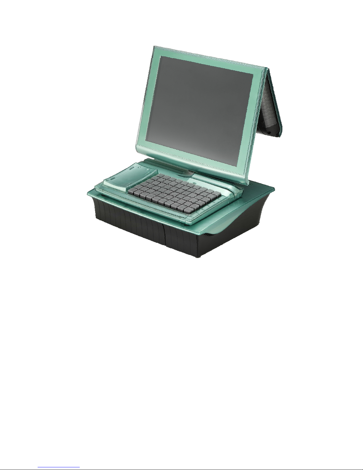
RichPOS-2000
Keyboard Connector Board
9000
C
B0830
HDD Case
HDD
Internal I/O Connector Board
9000CB0810
Front I/O Door
Aluminum Base
Front I/O Panel
Acrylic Top Cover
Memory Heatsink
Rear I/O Panel
FIR-ULV600-DVR Main Board
4
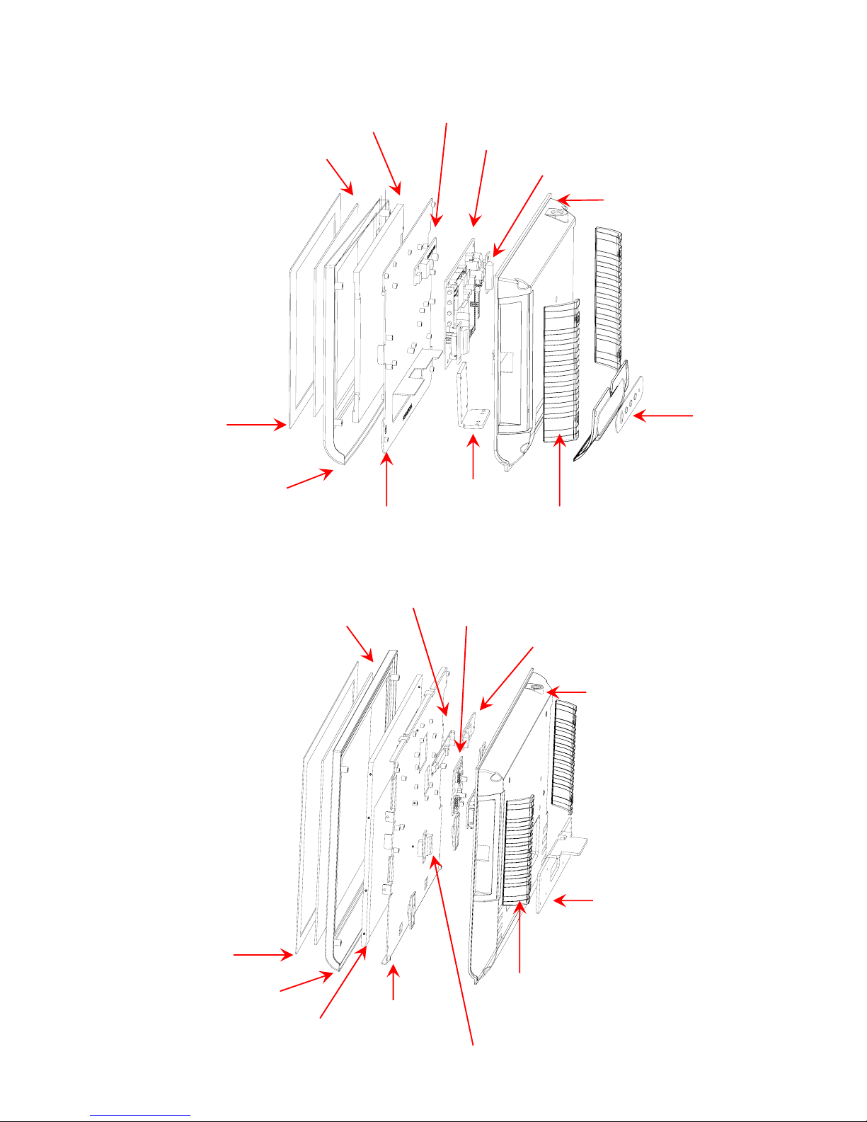
8.4” RichPOS-2000
14.1” RichPOS-2000
Hinge Holder
Blanking Covers
PC Film
Acrylic Front Cover
LCD Panel Panel Holder
IC Card Reader Connector Board
Aluminum Back Cover
MCR Connector Board
Touch Panel Inverter LVDS Converter Board
OSD Keypad
Blanking Covers
Hinge Holder
Panel Holder
Acrylic Front Cover
PC Film
Touch Panel
LCD Panel Inverter
A/D Board
MCR Connector Board
Aluminum Back Cover
FIR-ULV600-DVR Main Board
5
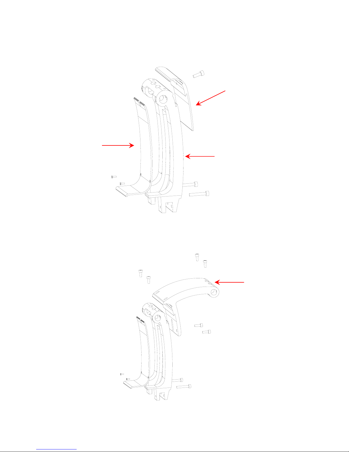
Single LCD Panel Holder
Dual LCD Panel Holder
Hinge Cover
LCD Mounting Post
Cable Cover
Secondary LCD
Mountin
g
Post

FIR-ULV600-DVR Main Board
6
What comes with RichPOS-2000
14” RichPOS -2000
With VFD customer display
14” RichPOS-2000
With 8.4” TFT-LCD Panel customer display
The following items are standard with
RichPOS-2000:
•Main system with 14” or 8” LCD
panel
•Power adapter
•User’s guide
•FIR-ULV600-DVR motherboard
user’s guide
•Motherboard chipset driver CD
•AC power cord
The following items are optional:
•8.4” TFT-LCD Customer
Display
•60 keys keyboard with
Magnetic Card Reader
(MCR).
•VFD customer display
•Wireless LAN
FIR-ULV600-DVR Main Board
7
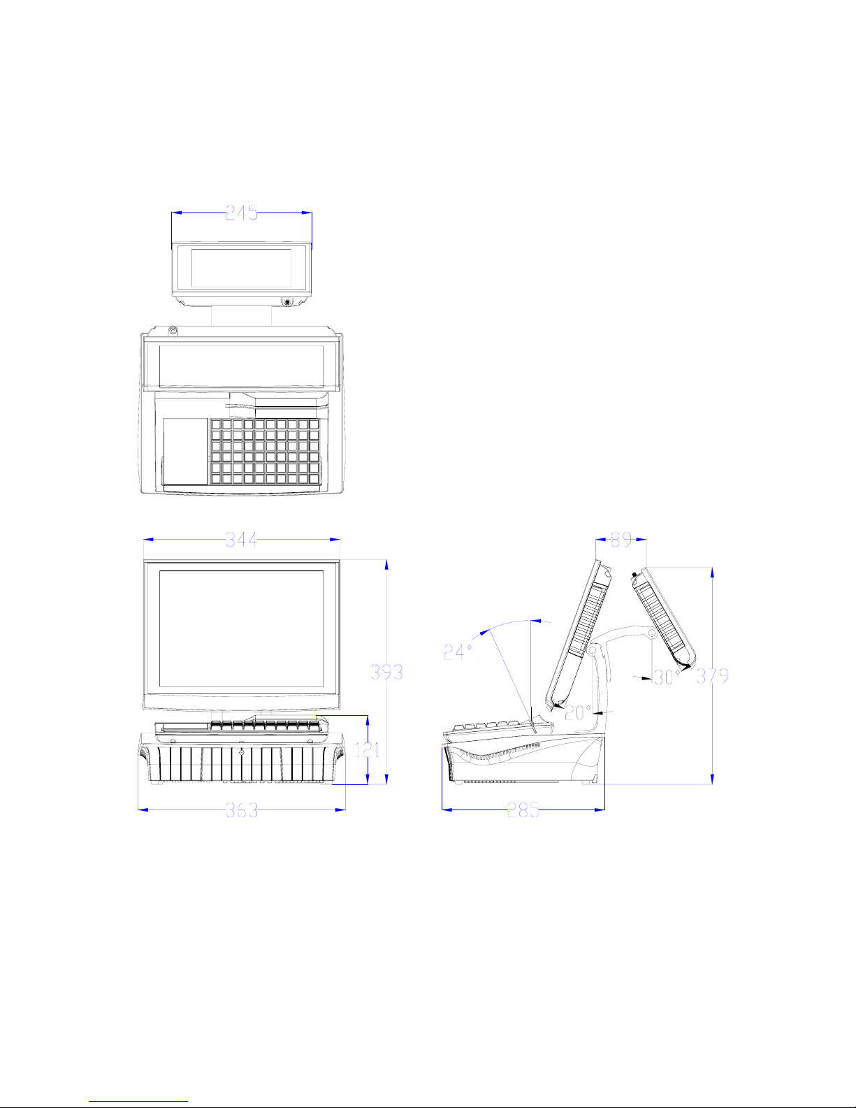
RichPOS-200 Dimensions

FIR-ULV600-DVR Main Board
8
FIR-ULV600-DVR Main Board
9
Connector Panels
Font Connector Panel
I/O Port Connector Type Description
USB 3 & 4 USB Type A These are USB version 2.0 ports and can be used
to connect most USB devices.
VGA VGA Connector The VGA port is for use with an external LCD or
CRT monitor.
K/B PS/2 Keyboard
Connector The K/B port for an external keyboard.
PWR SW Power Switch
Tactile Switch ATX power switch function.
PWR LED Power LED
PWR PWR K/B USB VGA
LED SW 3&4

FIR-ULV600-DVR Main Board
10
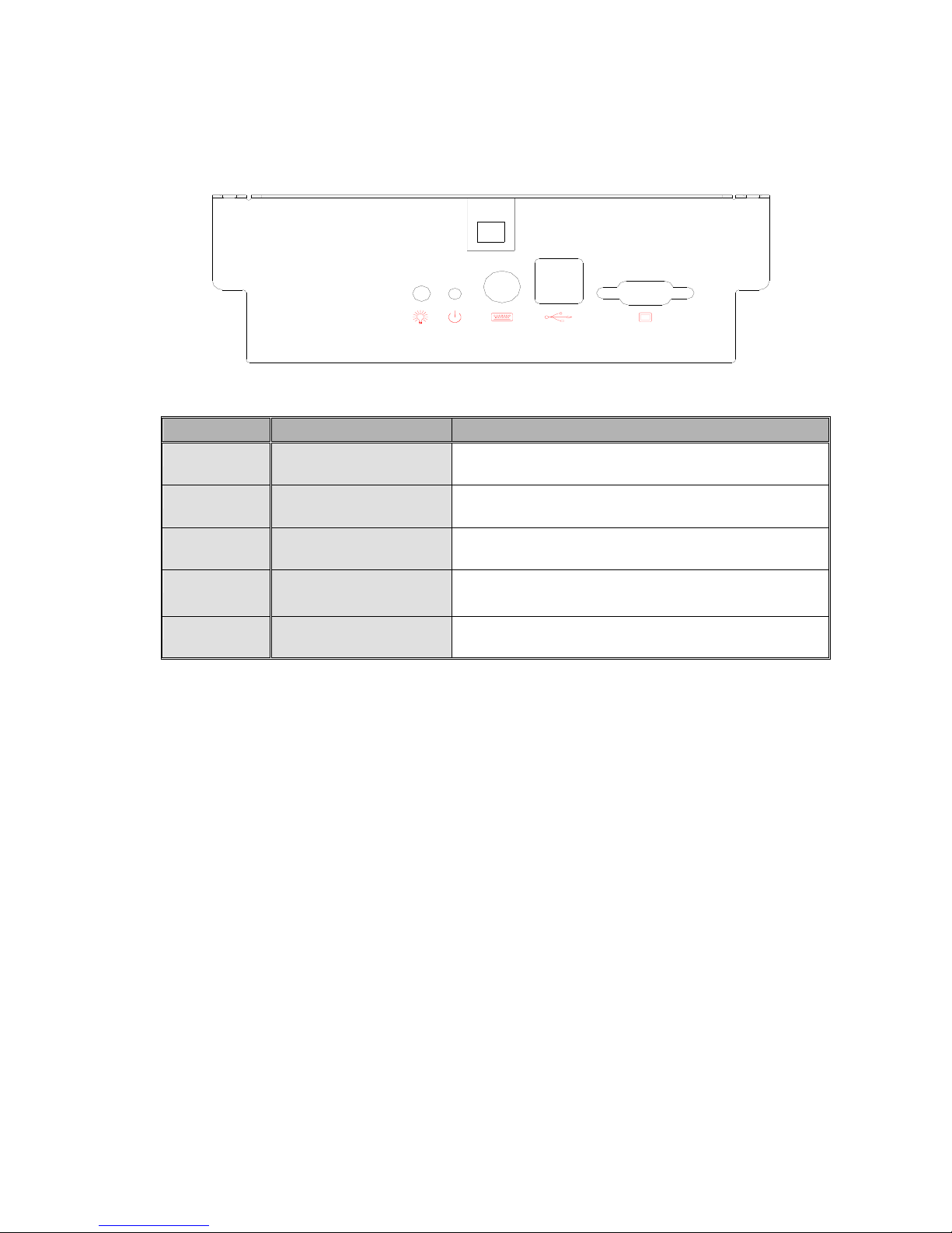
Rear Connector Panel
I/O Port Connector Type Description
Power DC Power Connector Connects RichPOS-2000 to the power supply.
Cash Drawer RJ11 Connector Cash Drawer Connector, 12 V Actuation support
for solenoid.
Line Out Earphone Connector The audio port is for speakers.
LAN LAN RJ45 Connector The LAN port is used to hook RichPOS-2000 to a
local area network.
COM1、COM2
COM5、COM6 D-sub Connector
The serial ports COM1/COM2/COM5/COM6 can
be used to connect serial devices such as a serial
printer or a fax/modem. (Note 1)
COM4 VFD/ COM4 RJ45
Connector This RJ45 port is used to attach a VFD customer
display or may be used as an additional serial port.
USB 1 USB A Connector This is a USB version 1.1 for additional devices
Note1: Com5 & Com6 ports will be assigned with DVR Application
Powe
r
LINE LINE
IN
OUT
USB1 LAN COM4
COM2 COM1
COM5 COM6
C
as
h
Drawer
LPT1
FIR-ULV600-DVR Main Board
11
C
Ch
ha
ap
pt
te
er
r
2
2
H
Ha
ar
rd
dw
wa
ar
re
e
S
Se
et
tu
up
p
RichPOS-2000 Assembly
Please make sure that the power supply is disconnected when making any hardware changes to
RichPOS-2000.
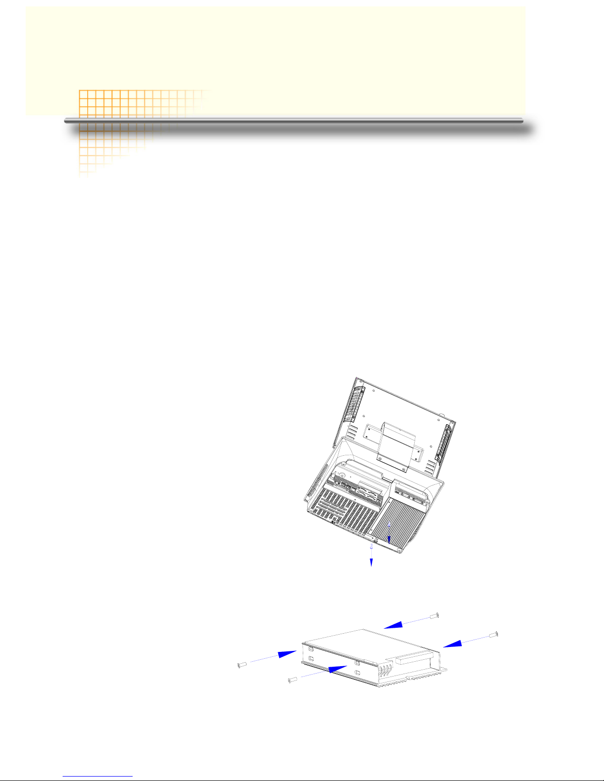
Hard Disk Drive Installation
A standard RichPOS-2000 comes without a hard disk drive (HDD), unless it is pre-requested.
Installing a HDD
1. Turn off power and remove power cable from main unit.
2. Remove two screws
from the HDD cover
3. Place HDD on the
HDD cover with 4
screws.

FIR-ULV600-DVR Main Board
12
4. Connect the existing 40pin ribbon cable and 4pin power cable to the HHD
5. Screw the cover back
to the unit with two
screws.
6. Connect the main unit power.
Note: If the HDD does not work normally, please refer to troubleshooting

FIR-ULV600-DVR Main Board
13
60keys Keyboard Installation
Installing60Keys Keyboard
1. Turn off power and remove power cable from RichPOS-2000.
2. The Keyboard is install or
replace at the vertical
direction
There are two types of
keyboard available , one
include USB 4 ports Hub,
this is reserved for customer
specific devices the other is
without USB Hub function,
please refer to 9000PB0810
I/O Board Jumper setting
USB2 signal routing Jumper
J2 and J3
Keyboard
Socket

FIR-ULV600-DVR Main Board
14
14” 1st TFT-LCD Display Installation
Installing 1st VGA Display
1. To remove60 Key’s
keyboard
2. To remove 2 screw of the
cover from the neck
3. Insert 1st LCD Panel Cable
through the neck and to
Case bottom
LCD Cable
Table of contents


