Firmtec ELB 1985 User manual

Connection to Vehicle
It is strongly recommended that the unit is connected to the vehicle
through a fused supply using the supplied cable.
When using the supplied cable the positive connection is made to the
core white wire. The negative (ground) connection is made to the
outer core (screening). It is not possible to damage the unit through
connecting the cable the wrong way around however the unit will
only work when connected correctly.
Specification
Supply Voltage 11 15VDC
Power Connector 2.1mm (5.5mmOD) +VE centre pin
GPS Chipset SiRF Star III
Accuracy Max 0.1ms-1
Antenna 1575.42MHz Chip (L1C)
We hope you enjoy using this product as much as we enjoyed developing it!
Developed and Manufactured by
Advent Controls Ltd, Liverpool, UK
Made in UK
RETRO GPS<….……
speedometer
ELB 1985
2-Digit GPS Speedometer
with Speed Warning Alarm
www.firmtec.co.uk

EMC/EMI Compliance Statement: CE Mark Declaration of Conformance
This product conforms to the following specifications:
• EMC: EN55 22
• Safety: EN6 95
• Immunity: EN55 24
This product complies with European Directive 199 / /EC.
Manufacturer's Disclaimer Statement
The information in this document is subject to change without notice and does not repre-
sent a commitment on the part of the vendor. No warranty or representation, either ex-
pressed or implied, is made with respect to the quality, accuracy or fitness for any particu-
lar purpose of this document. The manufacturer reserves the right to make changes to the
content of this document and/or the products associated with it at any time without obli-
gation to notify any person or organisation of such changes. In no event will the manufac-
turer be liable for direct, indirect, special, incidental or consequential damages arising out
of the use or inability to use this product or documentation, even if advised of the possibil-
ity of such damages. This document contains materials protected by copyright. All rights
are reserved. No part of this manual may be reproduced or transmitted in any form, by
any means or for any purpose without expressed written consent of its authors. Product
names appearing in this document are mentioned for identification purchases only. All
trademarks, product names or brand names appearing in this document are registered
property of their respective owners.
Contents
Introduction 3
Operation 3
Touch Switches 4
Menu Items 5
Display Modes 5
Display Units 6
Power Management 6
Touch Switch Sensitivity 7
Speed Limit Warning Alarm 7
Connection to Vehicle 8
Specification 8
Touch Switch Sensitivity
The capacitive touch switches are more sensitive to large fingers than smaller
ones. If the user finds the switches are too sensitive they can decrease the
sensitivity of the switches by increasing the ‘Sensor Adjust’ value as shown in
Table 1. Conversely if the user finds the sensor is too insensitive the ‘Sensor Ad
just’ value can be decreased. Note sensitivity is the inverse of the sensor ad
just value.
Speed Limit Warning Alarm
The speedometer incorporates a speed limit warning alarm and pre alarm.
The user can set a speed limit between 1 and 99units (kph or mph). When the
vehicle travels over this speed an alarm will sound. A pre alarm can also be
set to assist the driver in maintaining a constant speed below the limit. The
pre alarm can be set between 1 and 9units below the alarm speed. The
speed limit warning alarm is more accurate than the value on the display as it
is not affected by rounding errors.
To set the speed limit alarm the right hand ‘DOWN’ touch switch is pressed
once. The speedometer will then display the current alarm speed setting.
The user can then press the ‘UP’/’DOWN’ switches to vary the alarm speed.
The amount either the ‘UP’ or ‘DOWN’ switch increments or decrements the
speed is controlled by the ‘Speed Limit Increment Value’ set in the main
menu. By default this is set to 10 (N.B. a value of 10 is shown as ‘0’ in the
menu).
The pre alarm is a useful feature which warns the driver that he/she is ap
proaching the alarm speed. The default tone is very discreet and can sound
continuously without causing annoyance.
To change the pre alarm and alarm tone the values of ‘P’ and ‘A’ in the main
menu are set as per Table 2.
Table 2 Tone Selection
Value Description
0 Bleep Pause
1 Alternating Tone
2 Melody
3 Infinite Tone

Display Units
The speedometer can display speed in either kph or mph. To switch
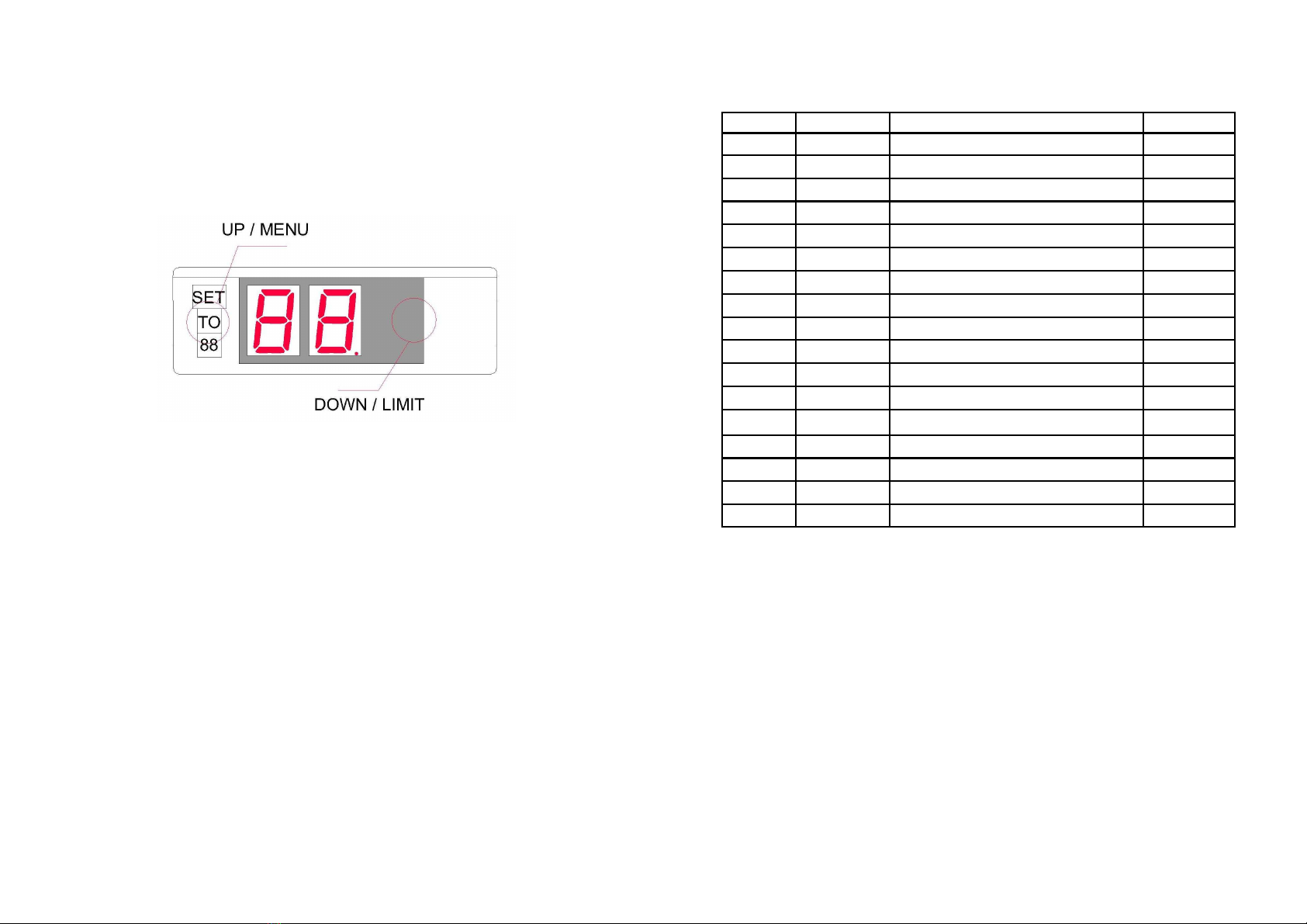
between kph and mph scroll though the menu by pressing the left
hand side ‘UP’ touch switch until ‘U’ is displayed on the left hand (tens)
display. Press the ‘DOWN’ touch switch to modify the value as per Ta-
ble 1. The units selected also affect the speed limit alarm speed and
the pre/alarm speed difference value. These are re calculated auto
matically.
Power Management
When stationery, the speedometer automatically shuts down after the
‘Auto shutdown time’ (see Table 1 for details). If this is undesirable the
device can operate in ‘Always on’ mode. To switch between auto
power management and always on modes scroll though the menu by
pressing the left hand side ‘UP’ touch switch until ‘E’ is displayed on the
left hand (tens) display. Press the ‘DOWN’ touch switch to modify the
value as per Table 1.
The unit can be shutdown at any time by scrolling through the menu
until ‘0n’ is displayed and pressing the ‘DOWN’ touch switch. Please
note that to restart the speedometer either the ‘UP’ or ‘DOWN’ touch
switch must be pressed – the speedometer will not restart in response to
movement if shutdown this way.
If the speedometer is operating in auto power management mode it
automatically shuts down the display after the ‘Auto shutdown time’.
The GPS chipset will then enter trickle power mode to keep the internal
clock synchronised with the GPS satellites. If the vehicle then travels at
a speed greater than 5knots then the device wakes from sleep and
resumes normal operation.
Note if the vehicle is parked in a covered area, such as a garage, the
GPS chipset will remain at full power in an attempt to reacquire a lock
with the satellites. It would take approximately 2 months for the device
to discharge a typical car battery in this mode and is likely not to be
the greatest drain on the vehicle battery when not in use. However, if
the vehicle is regularly parked up for several days we recommend dis
connecting the speedometer.
Introduction
The Firmtec Retro GPS speedometer uses the GPS satellite cluster to calculate
the speed of the vehicle and requires only a simple power connection. It is
able to display speeds of up to 199mph and can display vehicle speed in
miles per hour (mph) or kilometres per hour (kph).
The speedometer is based around the best in class SiRF Start III GPS chipset
which features low power consumption, high sensitivity and accurate dop
pler corrected velocity measurements.
The speedometer also incorporates a speed limit warning alarm and pre
alarm and a menu accessed by capacitive touch sensitive switches. The user
can set a speed limit between 1 and 99units (kph or mph). When the vehicle
travels over this speed an alarm will sound. A pre alarm can also be set to
assist the driver in maintaining a constant speed below the limit. The pre
alarm can be set between 1 and 9units below the alarm speed.
Operation
The unit will only operate in full view of the sky when oriented the right way
up. GPS signals will pass through thin non metallic surfaces, such as a car
windscreen, but it is not able to operate indoors.
If the unit has been disconnected for over two hours then it will need to up
date almanac and ephemeris data from the GPS satellites. This may take up
to 3 minutes depending on the strength of the GPS signal. If the unit receives
a momentary disconnection of power then valid data should be ready within
8 seconds.
The decimal point will illuminate only when sufficient satellites have been ac
quired and they are supplying valid data. On certain models a reading will
only be displayed when valid data is present and at least 4 satellites have
been acquired.
The accuracy of the unit will increase as more satellites are acquired. This will
take several minutes from a cold start. Please note the GPS module has an
internal battery to store ephemeris data which is used to perform a warm
start. When shipped this battery will be discharged and may take several
hours of normal operation to charge.

Touch Switches
The menu functions and speed limit alarm speed are accessed using
the capacitive touch sensitive switches on the front of the speed
ometer. Capacitive touch sensors were used to add a lot of func
tionality without affecting the overall appearance of the speedome
ter. The sensors are located behind the ‘TO’ legend and in the far
right centre of the bezel as shown in Figure 2.
Figure 2 Touch Switch Locations
During the initial splash screen which displays
‘ELB’
the capacitive
touch sensors are undergoing rapid calibration and must not be
touched during this time. If the switches are pressed during this time
they may remain un responsive to touch for up to a minute whilst slow
recalibration occurs in normal operation.
The left hand ‘UP’ touch switch is used to access the main menu,
scroll through the menu items and increment the value on display.
The menu item is shown on the left hand display and the value is
shown on the right hand display. To select a menu item the right
hand ‘DOWN’ switch is pressed. The ‘UP’ and ‘DOWN’ switches are
then used to modify the value of the menu item. Once the value has
been selected the user waits for the menu to close saving the modi
fied value.
In normal operation the right hand ‘DOWN’ switch is used to enter the
speed limit warning set speed menu. See ‘Speed Limit Warning
Alarm’ for more information.
Menu Items
Table 1 Menu Items
Display Modes
The unit can operate in two display modes; scroll and step. In scroll mode,
if the vehicle acceleration is less than 10units per second, the display will
scroll incrementally through every number up (or down) to a steady state
speed. In step mode the display is updated every second with the current
vehicle speed. Lag is reduced in step mode and is hence more accurate.
To switch between scroll and step modes scroll though the menu by press
ing the left hand side ‘UP’ touch switch until ‘S’ is displayed on the left hand
(tens) display. Press the ‘DOWN’ touch switch to modify the value as per
Table 1.
Item Range Description Default
L
0 3 Brightness 3
0
Shutdown
b
0 2 Buzzer Volume 2
s
0 1 Scroll Mode (en=1, dis=0) 1
d
0 9 Pre/Alarm Difference 3
U
0 1 Units (mph=0, kph=1) 0
P
0 3 Pre alarm Tone 0
A
0 3 Alarm Tone 2
t
0 9 Auto shutdown time 3
E
A/n Auto (A)/Always on (n) A
r
Reset Defaults
o
1 10 Speed Limit Increment Value 0 (10)
|-
0 9 Left Sensor Adjust 5
-|
0 9 Right Sensor Adjust 5
v
Display Firmware Version
@
Display Satellite Data
Popular Automobile Accessories manuals by other brands

Menabo
Menabo HIMALAYA installation instructions

Kenwood
Kenwood KCA-BT100 instruction manual

Uebler
Uebler 15720 Mounting and operating instructions

Tuffy
Tuffy 182 installation instructions

Havis-Shields
Havis-Shields Side Slide-Out Step 1997-2007 Chevrolet Full Size Van... installation instructions

TruXedo
TruXedo TRUXPORT Pro X15 owner's manual

Axxess
Axxess AXDSPL-WR installation instructions

Car-Interface
Car-Interface CI-RL2-MZD manual

Whelen Engineering Company
Whelen Engineering Company SAK23 installation guide

Thule
Thule Awning 326 Assembling instructions

Front Runner
Front Runner FATF006 quick start guide

Whistler
Whistler WBU-1000 user guide