Husky GM UPRIGHTS Assembly instructions

All Products limited to Vehicle Tow Rating, see Vehicle Owners Manual. Visit www.huskytow.com for Warranty Information /
Tech Support / Product Updates. 2021 Keystone Automotive Operations Inc. All Rights Reserved. 05/17/2021-Rev1 Page-1
APPLICATION:
GM 2500/3500– vehicle must have OEM 5th wheel/Gooseneck Hitch Prep Package
This kit is to be used ONLY with Husky kits:
32998 (HUSKY 16KW/26W CROSSMEMBER KIT), 32998 REQUIRES THE PURCHASE OF 31569 (16KW) OR 33157 (26KW)
32999 (HUSKY 16KS CROSSMEMBER KIT), 32999 REQUIRES THE PURCHASE OF 31453
If the truck is raised, be sure that the truck is properly blocked and restrained to prevent the truck from
falling. Failure to do so may result in the truck suddenly falling, causing death or serious injury.
CAUTION:
These instructions are guidelines only. Actual installation is the responsibility of the installer and the
owner. Always measure truck and trailer before installing hitch to be sure that there is clearance at the
cab and at the bumper to allow for turns.
NOTICE
Husky recommends to always drive the king pin into the hitch throat and not drop the king pin from above into the
hitch head to avoid incorrect hook-ups. Please read Operating Instruction to understand how this important Safety
Feature operates.
Refer to instructions: 32998 & 32999 for proper installation of those products.
Never exceed the
towing capacity of the tow vehicle.
Use only the supplied bolts, nuts, and washers to install this kit. All
nuts and bolts are Grade 5 unless specified otherwise.
Assembly, Installation, Operation and
Maintenance Instructions
GM UPRIGHTS
P/N: 33221
60-90 minutes
Dealer / Installer: Provide a copy of these instructions to the end user of this product. These
instructions provide important operating and safety information for proper usage of
this product. Demonstrate the proper use of the product with the end user. Have the
end user demonstrate that they understand the proper use of the product.
End User: Read and follow all instructions included in this manual. Ask your Dealer / Installer
for assistance if you do not understand the proper use of the product. Never remove
any decals from the product. Failure to follow these instructions can result in injury
or death.
WARNING
WARNING
WARNING

All Products limited to Vehicle Tow Rating, see Vehicle Owners Manual. Visit www.huskytow.com for Warranty Information /
Tech Support / Product Updates. 2021 Keystone Automotive Operations Inc. All Rights Reserved. 05/17/2021-Rev1 Page-2
Parts Diagram
1
4
7
2
3
5
11
6
9
8
12
10
PARTS LIST
ITEM NO. DESCRIPTION QTY.
1UPRIGHT2
2 ADAPTOR 4
3T-BOLT4
4 HANDLE ASSEMBLY 4
5 TAB WASHER 4
6 1”-14 JAM NUT 4
7 3/16” LOCK PIN 4
8¾”-10 X 1-3/4” SOCKET HEAD
CAP SCREW 4
9 ¾”-10 NYLOCK HEX NUT 4
10 5/16" LOCK PIN 2
11 SPACER 4
12 INSTRUCTIONS 1

All Products limited to Vehicle Tow Rating, see Vehicle Owners Manual. Visit www.huskytow.com for Warranty Information /
Tech Support / Product Updates. 2021 Keystone Automotive Operations Inc. All Rights Reserved. 05/17/2021-Rev1 Page-3
1. Place both uprights into GM 5th Wheel adaptor installed in your truck from the factory. The handles and T-bolts
must be rotated into the Un-locked position.
Handles and T-Bolts are shown
in the Un-Locked Position
Truck bed NOT shown for
clarification purposes
Handles and T-Bolts are
shown in the Un-Locked
Position
Handles and T-Bolts are shown
in the Locked Position
T-Bolts are shown parallel to 5th
Wheel adaptor
Handles and T-Bolts are shown
in the Un-Locked Position
T-Bolt
5th Wheel adaptor

All Products limited to Vehicle Tow Rating, see Vehicle Owners Manual. Visit www.huskytow.com for Warranty Information /
Tech Support / Product Updates. 2021 Keystone Automotive Operations Inc. All Rights Reserved. 05/17/2021-Rev1 Page-4
2. Once uprights are installed; turn handles into the locked position. Adjust the T-bolts for a looser or tighter fit by
rotating them in the handles.
3. Install the cross member from kit 32998 or 32999 to uprights (#1) using the ¾”-10 bolts (#8) and ¾”-10 nylock nuts (#9).
Kit 32998 shown below as an example; kit 32999 installs similarly.
Important: install bolts on the inside of the crossmember and nuts on the outside of the crossmember.
Handles and T-Bolts are shown
in the Locked Position
Handles and T-Bolts are shown
in the Locked Position

All Products limited to Vehicle Tow Rating, see Vehicle Owners Manual. Visit www.huskytow.com for Warranty Information /
Tech Support / Product Updates. 2021 Keystone Automotive Operations Inc. All Rights Reserved. 05/17/2021-Rev1 Page-5
4. Once the crossmember is installed; make sure the adaptor sits FLAT with the 5th Wheel Adaptor at ALL 4 contact locations.
Torque all four ¾”-10 bolts and ¾”-10 nylock nuts to 250 ft.lbs.
APPLY TORQUE WRENCH TO THE NUTS NOT THE BOLTS.
GM 5th Wheel Adaptor
AdaptorAdaptor
5. Rotate handles to the locked and unlocked positions. All 4 handles should rotate easily. Check to be sure that hitch
assembly (uprights & crossmember) do NOT “rock” back and forth easily and that the adaptors remain flat with the GM 5th
wheel adaptor. If the handles do not rotate easily OR if the hitch assembly “rocks” and does not stay flat; you need to
adjust the T-bolts up or down by rotating them in the handles. We recommend you do this in half turn increments. Plus, this
may take a few times to get adjusted correctly. All trucks are not made the same and require different amounts of
adjustment. BE PATIENT.
6. Rotate handles to the unlocked position and remove hitch assembly (uprights & crossmember) from the GM 5th wheel
adaptors. IF the hitch assembly does NOT remove easily; loosen the 1” jam nuts and adjust the adaptors so that the hitch
assembly easily removes. Re-tighten 1” jam nuts.
7 Once the hitch assembly removes easily, the handles rotate easily AND there is no “rock” in the hitch assembly with the
GM 5th Wheel adaptor you can tighten the 1” jam nuts with an adjustable wrench until tight.
8. Bend 1 of the tabs on each of the tab washers (5) up and against the side of the jam nut. This will keep the 1” jam nut from
loosening.
Handles and T-Bolts are shown
in the Locked Position
Area to be flat
Area to be flat
Bent Tab on
Tab Washer

All Products limited to Vehicle Tow Rating, see Vehicle Owners Manual. Visit www.huskytow.com for Warranty Information /
Tech Support / Product Updates. 2021 Keystone Automotive Operations Inc. All Rights Reserved. 05/17/2021-Rev1 Page-6
9. Finally, install the 5/16” D-Lock pins through the handles and the uprights.
5/16" LOCK
PIN WITH THE
CLASP
OPENED AND
UN-LOCKED
PAD LOCK
SHOWN
LOCKING
THE
HANDLES
SECURELY
5/16” LOCK
PIN WITH THE
CLASP
CLOSED AND
LOCKED
5/16" LOCK PIN WITH THE CLASP
CLOSED AND LOCKED
NEVER TOW WITHOUT LOCKING THE 5TH WHEEL HITCH HANDLES WITH EITHER THE PROVIDED
5/16" LOCKPINS OR A PAD LOCK.
NEVER TOW WITHOUT LOCKING THE HANDLES WITH THE PROVIDED 3/16" LOCKPINS.
3/16" LOCK PIN SECURED AND LOCKED
THRU THE HANDLE AND T-BOLT
WARNING

All Products limited to Vehicle Tow Rating, see Vehicle Owners Manual. Visit www.huskytow.com for Warranty Information /
Tech Support / Product Updates. 2021 Keystone Automotive Operations Inc. All Rights Reserved. 05/17/2021-Rev1 Page-7
Preparing For First Use
1. Verify that the cross member is set at the proper height to provide a minimum of 6" clearance between the bottom of the
trailer nose and the top of the truck bed sides and allows for a level-towing attitude of the 5th Wheel Trailer (See Figure 1
below).
2. With top face of head level measure up to top of pickup box (dimension Y in Figure 1). On the trailer measure up from the
face of the pin box to the underneath of the trailer (dimension X in Figure 1). Measurement X less measurement Y gives the
amount of clearance between the top of the pickup box and the underneath of the trailer.
At a minimum this should be 6”, if the trailer and tow vehicle are going off-road then this needs to be 8” to 10”.
If this dimension is less than 6” DO NOT USE THIS TRAILER WITH THIS TOW VEHICLE. Severe damage may occur
to both the pickup box and the trailer.
3. If necessary, adjust the cross member to the proper height, ensuring the fasteners are re-torqued to 250 ft.lbs.
4. Ensure the 5th Wheel Trailer wheels are blocked front & rear & that the rear stabilizer jacks are fully retracted.
5. Also make sure the 5th Wheel Trailer landing leg feet are on a stable surface.
6. With hitch head level, set trailer king pin box ½” to 1” below hitch so trailer will ride up and onto hitch. Back Up the truck
under the trailer so the king pin enters the hitch.
Figure 1

All Products limited to Vehicle Tow Rating, see Vehicle Owners Manual. Visit www.huskytow.com for Warranty Information /
Tech Support / Product Updates. 2021 Keystone Automotive Operations Inc. All Rights Reserved. 05/17/2021-Rev1 Page-8
7. Open the handle to your 5th wheel according to the instructions provided to that specific product.
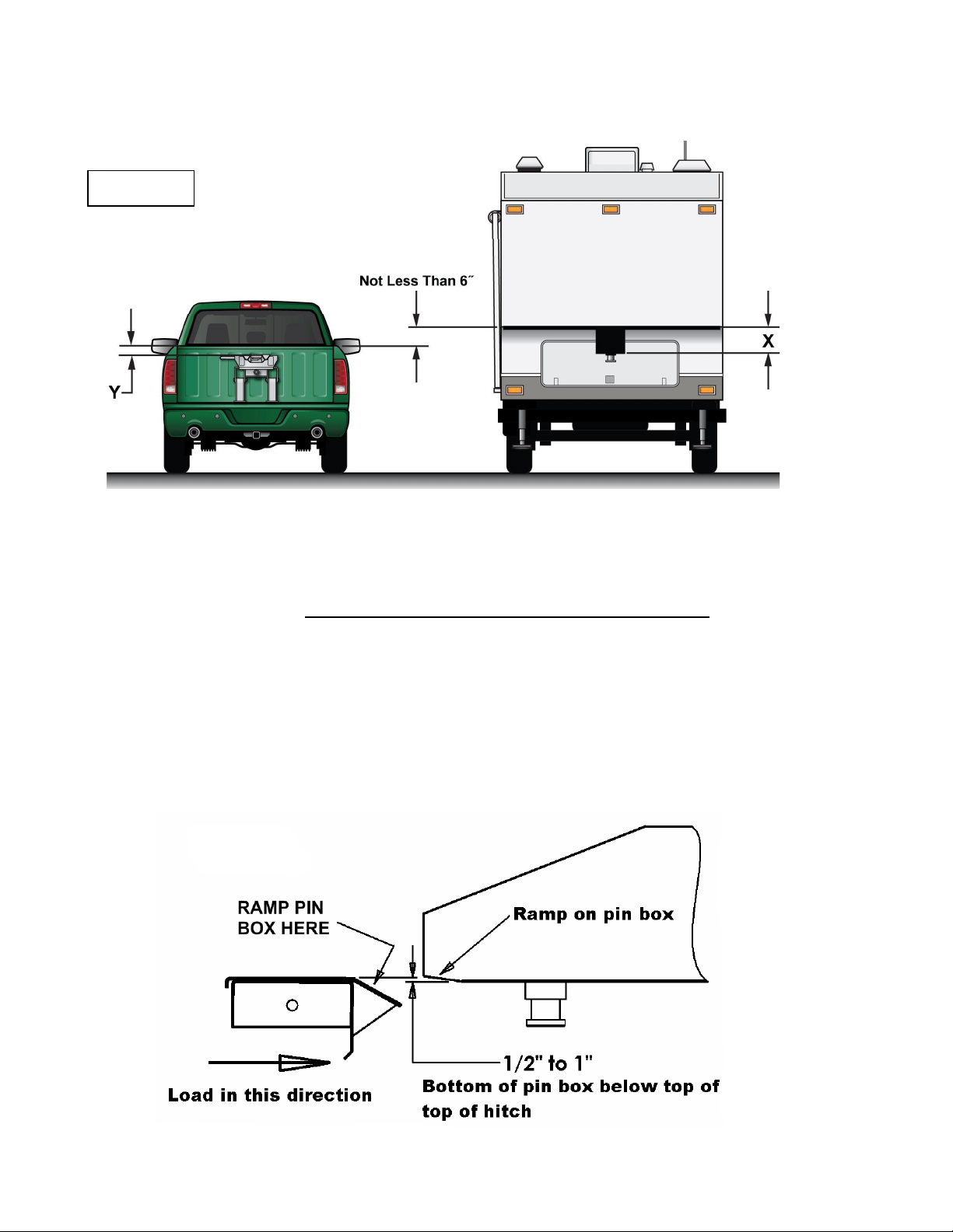
8. Slowly back the truck so that the bottom plate of the king pin box slides onto the 5th wheel plate & the king pin slides fully
into the throat of the hitch head. Set the parking brake of the truck & place the transmission into park.
9. Visually verify that the 5th wheel slide bar or jaw has closed behind the king pin and the king pin box is resting on the 5th
wheel plate.
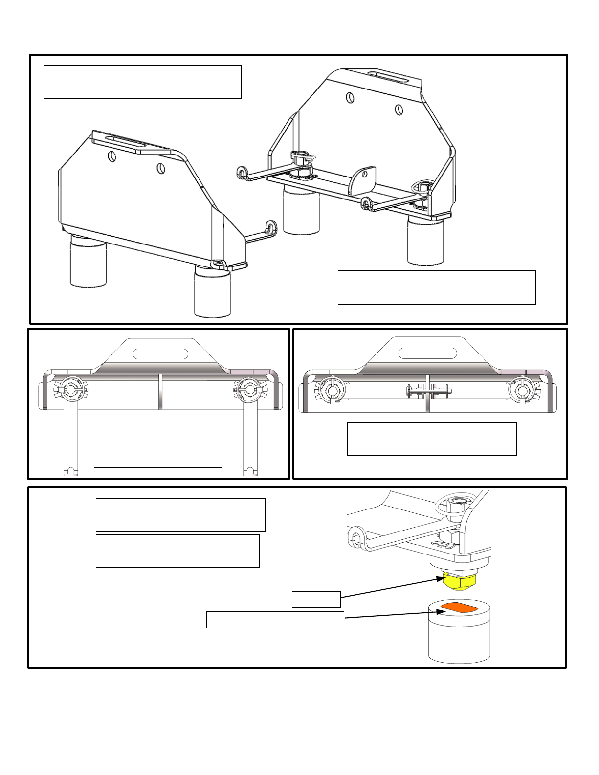
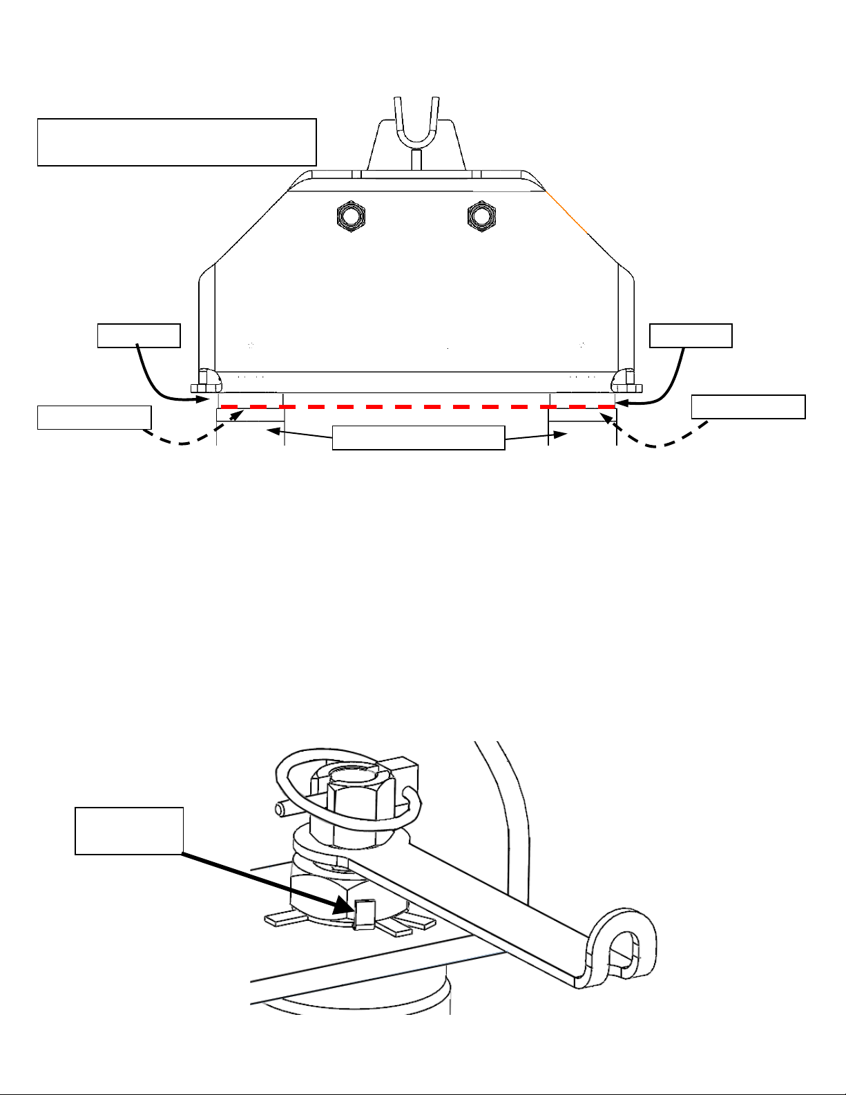
If using 5th wheel head 31453 (16KS): Positively lock the slide bar by rotating the handle clockwise so the handgrip is
pointing straight down at the bed of the truck. The red indicator sleeve on the handle shaft should not be visible when
correctly hitched up and the green indicator shaft should be protruding from the side of the hitch head.
If using 5th wheel head 31569 (16KW) OR 33157 (26KW): Positively lock the jaw and handle so that the handle is in the
closed position and the orange indicator is covered. The indicator should be protruding from the back of the hitch head.
Install the supplied locking clevis pin or pad lock through the lock hasp to retain the hitch closed.
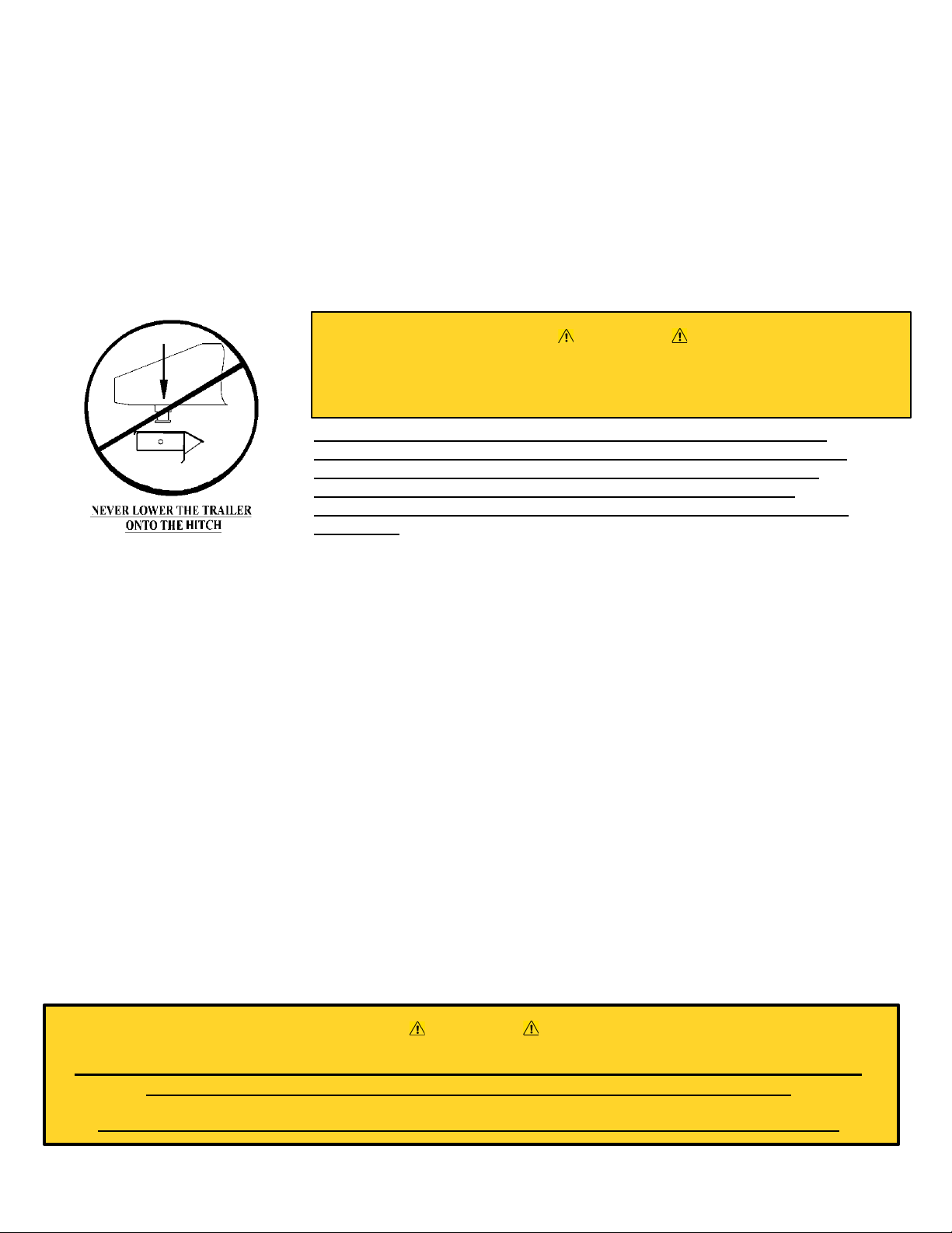
NEVER LOWER THE KING PIN INTO THE HITCH USING THE TRAILER
JACKS. THIS IS A VERY DANGEROUS PRACTICE AND WILL RESULT IN
THE KING PIN SITTING ON TOP OF HITCH INSTEAD OF INSIDE. THE
TRAILER COULD THEN BECOME DETACHED FROM THE TRUCK
DURING TOWING CAUSING SERIOUS DAMAGE AND POSSIBLY INJURY
OR DEATH.
10. Before towing perform a tug test as follows: Ensure the landing gear of the 5th Wheel Trailer are extended to the
ground, chock the tires, and attach the electrical & breakaway connectors to the proper receptacles in accordance with your
5th Wheel Trailer owner's manual. Then apply the trailer brakes, and slowly try to pull the trailer forward. The trailer should
prevent the truck from moving.
11. Remove the blocks from the wheels of the 5th Wheel Trailer; fully retract the trailer jacks and double check that the hitch is
properly attached to your tow vehicle.
Uncoupling Your Trailer
1. Block your 5th Wheel Trailer wheels front & rear.
2. If necessary, start your truck & back up against the king pin to relieve pressure on the slide bar. Set the parking brake, put
the transmission into park and then turn off your vehicle.
3. Extend the landing gear of the 5th Wheel Trailer until the weight of the 5th Wheel Trailer is just off of the 5th wheel plate of
the hitch. Do not exceed 1/16" gap between the bottom plate of the king pin box and the tabletop of the hitch. Caution:
Raising the 5th Wheel Trailer too high while still connected can damage the hitch head as well as components of
your 5th Wheel Trailer. Do not extend the rear stabilizers of the 5th Wheel Trailer prior to or during uncoupling.
4. Disconnect the electrical and breakaway connectors in accordance with your 5th Wheel Trailer owner's manual. With the
rubber grip of the handle pointing straight down towards the bed of the truck, pull it straight out and then rotate it straight up
to lock the handle in the out position.
5. You are now ready to pull your truck slowly away from the 5th Wheel Trailer..
DO NOT TRIP THE HITCH MECHANISM BY HAND AS THIS CAN RESULT IN INJURY . IN NORMAL
OPERATION LEAVE THE HITCH OPEN UNLESS IT IS COUPLED TO A TRAILER.
ALWAYS PULL ON THE HANDLE TO OPEN THE HITCH BEFORE COUPLING THE TRAILER.
Never back the tow vehicle under the trailer king pin and then lower the king pin
into the hitch. This will result in high pinning and will result in hitch damage
and possible vehicle damage, injury or death!
WARNING
WARNING

All Products limited to Vehicle Tow Rating, see Vehicle Owners Manual. Visit www.huskytow.com for Warranty Information /
Tech Support / Product Updates. 2021 Keystone Automotive Operations Inc. All Rights Reserved. 05/17/2021-Rev1 Page-9
Maintenance
1. After coupling, always visually check that the slide bar or the jaw has closed completely across the
rear of the king pin and that the indicators are working properly.
IMPORTANT! All indicating features should work when you are done hitching up for travel.
2. After the first 100 miles, and at least once a year thereafter, inspect all bolts for proper tightness. Re-
tighten nuts if needed.
3. Once or twice a week when traveling, apply a few drops of lubricant to the pivot areas of the hitch.
4. Once or twice a year, apply a light coating of wheel bearing grease to the surfaces of the slide bar that
holds the king pin in place. For best results, apply the grease with the slide bar or jaw surfaces of the
5th wheel in the closed position.
Caution: The slide bar & jaws can close with heavy force. Use extreme care to keep fingers,
hands, extremities & clothing out of the path of the slide bar. Failure to do so could result in
severe injury.
5. Periodically inspect your product for wear or damage. If excessive wear or damage is found, contact
your installing dealer or send proof of purchase and photo of wear and damage to HUSKY technical
support staff at www.huskytow.com or 1-877-544-4449.
6. Husky Towing Products recommends the use of a lube disc, contact your local Husky dealer to
purchase one.
OEM
CROSSMEMBER
HARDWARE KIT
HANDLE, T-BOLT &
ADATER KIT
33182
33178
ITEM # PART DESCRIPTION
1UPRIGHT --
2ADAPTOR --
3T-BOLT -1
4HANDLE ASSEMBLY -1
5TAB WASHER -1
61”-14 JAM NUT -1
73/16” LOCK PIN -1
8¾”-10 X 1-3/4” SOCKET HEAD CAP SCREW 4-
9¾”-10 NYLOCK HEX NUT 4-
10 5/16" LOCK PIN -1
11 SPACER -1

All Products limited to Vehicle Tow Rating, see Vehicle Owners Manual. Visit www.huskytow.com for Warranty Information /
Tech Support / Product Updates. 2021 Keystone Automotive Operations Inc. All Rights Reserved. 05/17/2021-Rev1 Page-10
TOWING TIPS
Driving Tow Vehicle
Good habits for normal driving need extra emphasis when towing a trailer. The additional weight of the trailer affects
acceleration and braking. Extra time should be allowed for passing, stopping and changing lanes. Signal well in advance of a
maneuver to let other drivers know your intentions. Severe bumps and badly undulating roads can damage your towing
vehicle, hitch and trailer, and should be negotiated at a slow, steady speed. If any part of your towing system “bottoms out” or if
you suspect damage may have occurred in any other way, pull over and make a thorough inspection. Correct any problems
before resuming travel.
Turning and backing up present new problems-plan ahead. It is highly recommended that a spotter be used when backing up
to alert the driver of possible obstacles and prevent jack knifing the trailer.
Towing a trailer will change your turning radius, the longer the trailer the larger radius turn.
Driving Conditions
When driving in conditions where the pavement is wet, icy, snowy, loose gravel, grass and dirt, reduce speed and do not make
any sudden maneuvers. Allow ample distance/time for stopping and changing lanes. If possible, wait for road conditions to
improve before driving.
Follow all state, local and provincial driving and towing laws in the location you are driving in.
Not following your tow vehicle, trailer, and Husky instructions/manuals can result in a fatal accident.
Check Your Equipment
Please refer to the MAINTENANCE section. Periodically check the condition of all your towing equipment and keep it in top
condition.
Tire Inflation
Unless specified otherwise by the towing vehicle or trailer manufacturer, tires should be inflated to their manufacturer’s towing
recommendations.
Towing Vehicle and Trailer Manufacturers Recommendations
Review the owner’s manual for your towing vehicle and trailer for specific recommendations, capacities and requirements.
Passengers in Trailers
Trailers should not be occupied while being towed. Most states enforce this regulation.
Trailer Lights, Turn Signals, Electric Brakes
Always hook up all of the trailer lights, electric brakes and break-away switch connection whenever trailer is being towed. Also
periodically check functionality of all lights before towing and repair any problems as needed.
Remove Hitch When Not Towing
Remove hitch from the towing vehicle when not towing a trailer to reduce chances of accidental damage and to reduce the
chance of parts being stolen.
Maintenance
Keep movable hitch assembly parts (jaw, pivot pin, etc…) lubricated when not in use.
Remove 5th wheel hitch from receiver and store in clean, dry place when not in use.
At The Beginning of Every Towing Day:
If electric brakes are used ensure the emergency break away cable is attached to the tow vehicle.
Check to see that all electrical hook-ups are in working order and that the safety chains are securely connected.
Towing safely is the responsibility of the driver of the vehicle. Failure to tow safely can result in vehicle damage, bodily injury or
death.

All Products limited to Vehicle Tow Rating, see Vehicle Owners Manual. Visit www.huskytow.com for Warranty Information /
Tech Support / Product Updates. 2021 Keystone Automotive Operations Inc. All Rights Reserved. 05/17/2021-Rev1 Page-11
Warranty Terms:
10 Year Limited Warranty:
This warranty applies solely to Husky 5th Wheel products manufactured by Keystone Automotive
Operations Inc. for Husky Towing Products.
Husky Towing Products and Keystone Automotive Operations Inc. make no guarantees or warranties for
products not manufactured by Keystone Automotive Operations Inc. Such products are covered solely
under any applicable warranty of the manufacturer. It is always recommended that the operating
instructions and warranty instructions provided by the manufacturer are followed.
Keystone Automotive Operations Inc. warrants its products to be free from manufacturing and material
defects to the original purchaser for the length of warranty stated above from the date of retail purchase. If
any products are found to have a manufacturing or material defect, the product will be replaced or
repaired at the option of Husky Towing Products and Keystone Automotive Operations Inc. with proof of
purchase by the original purchaser. The original purchaser shall pay all transportation and shipping costs
associated with the return of the defective product and the defective product shall become the property of
Keystone Automotive Operations Inc.
The Warranty applies to Keystone Automotive Operations Inc. products used for individual and
recreational purposes. Commercial usage of the Keystone Automotive Operations Inc. products limits the
warranty to 90-days from date of purchase.
The Warranty applies only to Keystone Automotive Operations Inc. products which are found to be
defective in manufacturing or material. This warranty does not apply to normal wear and tear of the finish
placed on Keystone Automotive Operations Inc. products.
Husky Towing Products and Keystone Automotive Operations Inc. are not responsible for any labor costs
incurred for removal or replacement of the defective product.
Husky Towing Products and Keystone Automotive Operations Inc. are not responsible for repair or
replacement of any product under the limited warranty where the product was improperly installed,
misapplied, altered, abused, neglected, overloaded, misused or damaged as a result of an accident,
including any use of the product not in accordance with all product operating and safety instructions.
Without limiting the generality of the foregoing, Husky Towing Products and Keystone Automotive
Operations Inc. shall under no circumstances be liable for any incidental or consequential loss or damage
whatsoever arising out of, or in any way relating to any such breach of warranty or claimed defect in, or
non-performance of the products. Some states do not allow the exclusion or limitation of incidental or
consequential damages, so the above exclusion or limitation may not apply to you.
This limited warranty gives you specific legal rights, and you may also have other rights that vary from
state to state.

All Products limited to Vehicle Tow Rating, see Vehicle Owners Manual. Visit www.huskytow.com for Warranty Information /
Tech Support / Product Updates. 2021 Keystone Automotive Operations Inc. All Rights Reserved. 05/17/2021-Rev1 Page-12
EXIGENCE :
GM 2500/3500 – vehicle must have OEM 5e roue/ Ensemble de préparation pour attelage à col de cygne
À utiliser SEULEMENT pour les kits Husky :
32998 (HUSKY 16KW/26W KIT DE TRAVERSE), 32998 NÉCESSITE L'ACHAT DE 31569 (16KW) OU 33157 (26KW)
32999 (HUSKY 16KS KIT TRANSVERSAL), 32999 NÉCESSITE L'ACHAT DE 31453
Si le véhicule est soulevé, assurez-vous qu'il est correctement bloqué et retenu pour éviter qu'il ne tombe.
Le non-respect de cette consigne peut entraîner la chute soudaine du véhicule et provoquer des blessures
graves ou mortelles.
ATTENTION :
Ces instructions ne sont que des lignes directrices. L'installation réelle est la responsabilité de
l'installateur et du propriétaire. Mesurez toujours le véhicule et la remorque avant d'installer l'attelage
pour vous assurer qu'il y a un espace libre au niveau du pare-chocs pour permettre les virages.
REMARQUE
Husky recommande de toujours enfoncer le pivot d'attelage dans la gorge de l'attelage et de ne pas introduire le
pivot d'attelage par le haut dans la tête d'attelage afin d'éviter des accrochages mal réalisés. Veuillez lire les
instructions d'utilisation pour comprendre le fonctionnement de cet important dispositif de sécurité.
Veuillez vous référer aux instructions : 32998 & 32999 pour une utilisation correcte
de ces produits.
Ne jamais excéder la
capacité de traction du véhicule de remorquage
N’utilisez que les boulons, écrous et rondelles fournis pour installer ce kit.
Tous les écrous et boulons sont de classe 5, sauf indication contraire.
Instructions sur le montage,
l'installation, l'utilisation et l'entretien
UPRIGHTS GM
P/N: 33221
60-90 minutes
Revendeur /
Installateur :
Fournissez une copie de ces instructions à l'utilisateur final de ce produit. Ces
instructions contiennent des informations importantes sur le fonctionnement et la
sécurité pour une utilisation normale de ce produit. Présentez l'utilisation normale du
produit à l'utilisateur final. Demandez lui de confirmer qu'il a tout compris.
Utilisateur final : Veuillez lire et suivre toutes les instructions contenues dans ce manuel. Demandez
l'aide de votre revendeur / installateur si vous ne comprenez pas l'utilisation normale
du produit. Ne retirez jamais les autocollants du produit. Le non-respect de ces
instructions peut entraîner des blessures ou la mort.
AVERTISSEMENT
AVERTISSEMENT
AVERTISSEMENT
Tous les produits sont limités à l'évaluation de la capacité de remorquage du véhicule, voir le manuel du propriétaire du véhicule.
Consultez www.huskytow.com pour les informations sur la garantie / l'assistance technique / les mises à jour des produits. ©2021
Keystone Automotive Operations Inc. Tous droits réservés. 17/05/2021-Rév 1 Page 12

All Products limited to Vehicle Tow Rating, see Vehicle Owners Manual. Visit www.huskytow.com for Warranty Information /
Tech Support / Product Updates. 2021 Keystone Automotive Operations Inc. All Rights Reserved. 05/17/2021-Rev1 Page-13
Diagramme des pièces
1
4
7
2
3
5
11
6
9
8
12
10
LISTE DES PIÈCES
N° PIÈCE DESCRIPTION QTÉ.
1 SUPPORT 2
2 ADAPTATEUR 4
3BOULON EN T4
4 ASSEMBLAGE DE LA POIGNÉE 4
5 RONDELLE-FREIN 4
6 ÉCROU DE SERRAGE 1”-14 4
7GOUPILLE DE VERROUILLAGE
3/16” 4
8VIS À TÊTE CYLINDRIQUE À
SIX PANS CREUX ¾”-10 X 1-3/4 4
9ÉCROU HEXAGONAL NYLOC
¾”-10 4
10 GOUPILLE DE VERROUILLAGE
5/16" 2
11 CALE D’ESPACEMENT 4
12 INSTRUCTIONS 1
Tous les produits sont limités à l'évaluation de la capacité de remorquage du véhicule, voir le manuel du propriétaire du véhicule.
Consultez www.huskytow.com pour les informations sur la garantie / l'assistance technique / les mises à jour des produits. ©2021
Keystone Automotive Operations Inc. Tous droits réservés. 17/05/2021-Rév 1 Page 13

All Products limited to Vehicle Tow Rating, see Vehicle Owners Manual. Visit www.huskytow.com for Warranty Information /
Tech Support / Product Updates. 2021 Keystone Automotive Operations Inc. All Rights Reserved. 05/17/2021-Rev1 Page-14
1. Placez les deux montants dans l'adaptateur de la sellette GM installée en usine sur votre véhicule. Les
poignées et les boulons en T doivent être tournés en position déverrouillée.
Les poignées et les boulons en
T sont représentés en position
déverrouillée.
La caisse du véhicule n'est pas illustrée
pour une représentation plus claire
Les poignées et les boulons
en T sont représentés en
position déverrouillée
Les poignées et les boulons en T sont
représentés en position verrouillée
Les boulons en T sont
représentés parallèlement à
l'adaptateur de la sellette.
Les poignées et les boulons en T
sont représentés en position
déverrouillée
Boulon en T
Adaptateur de sellette
Tous les produits sont limités à l'évaluation de la capacité de remorquage du véhicule, voir le manuel du propriétaire du véhicule.
Consultez www.huskytow.com pour les informations sur la garantie / l'assistance technique / les mises à jour des produits. ©2021
Keystone Automotive Operations Inc. Tous droits réservés. 17/05/2021-Rév 1 Page 14

All Products limited to Vehicle Tow Rating, see Vehicle Owners Manual. Visit www.huskytow.com for Warranty Information /
Tech Support / Product Updates. 2021 Keystone Automotive Operations Inc. All Rights Reserved. 05/17/2021-Rev1 Page-15
2. Une fois les montants installés, placez les poignées en position verrouillée. Réglez les boulons en T pour un
ajustement plus ou moins serré en les tournant dans les poignées.
3. Fixez le kit transversal 32998 ou 32999 aux montants (#1) en utilisant les boulons ¾"-10 (#8) et les écrous nylock ¾"-10
(#9). Le kit 32998 est présenté ci-dessous à titre d'exemple ; le kit 32999 s'installe de la même manière.
Important: installez les boulons à l'intérieur de la traverse et les écrous à l'extérieur de la traverse.
Les poignées et les boulons en T sont
représentés en position verrouillée
Les poignées et les boulons en
T sont représentés en position
verrouillée
Tous les produits sont limités à l'évaluation de la capacité de remorquage du véhicule, voir le manuel du propriétaire du véhicule.
Consultez www.huskytow.com pour les informations sur la garantie / l'assistance technique / les mises à jour des produits. ©2021
Keystone Automotive Operations Inc. Tous droits réservés. 17/05/2021-Rév 1 Page 15

All Products limited to Vehicle Tow Rating, see Vehicle Owners Manual. Visit www.huskytow.com for Warranty Information /
Tech Support / Product Updates. 2021 Keystone Automotive Operations Inc. All Rights Reserved. 05/17/2021-Rev1 Page-16
4. Une fois la traverse installée, assurez-vous que l'adaptateur repose À PLAT sur l'adaptateur de la sellette AUX 4 POINTS
DE CONTACT. Couplez les quatre boulons ¾"-10 et les écrous nyloc ¾"-10 à 250 ft.lbs.
UTILISEZ LA CLÉ DYNAMOMÉTRIQUE SUR LES ÉCROUS ET NON SUR LES BOULONS.
Adaptateur de sellette
GM
Adaptateur
Adaptateur
5. Tournez les poignées en position verrouillée et déverrouillée. Les 4 poignées doivent pouvoir tourner facilement. Vérifiez que
l'assemblage de l'attelage (montants et traverse) ne peut PAS basculer d'avant en arrière et que les adaptateurs restent à plat
avec l'adaptateur de sellette GM. Si les poignées ne tournent pas facilement OU si l'assemblage de l'attelage bouge et ne reste
pas à plat, vous devez ajuster les boulons en T du haut ou du bas en les faisant tourner dans les poignées. Nous vous
recommandons de le faire demi-tour par demi-tour. De plus, cela peut prendre plusieurs essais avant d'être ajusté
correctement. Tous les véhicules ne sont pas fabriqués de la même façon et nécessitent des réglages différents.. SOYEZ
PATIENT.
6. Faites pivoter les poignées en position déverrouillée et retirez l'ensemble de l'attelage (montants et traverse) des adaptateurs
de la sellette GM. SI l'attelage ne se retire PAS facilement, desserrez les écrous de serrage de 1" et ajustez les adaptateurs de
façon à ce que l'attelage se retire facilement. Resserrez les écrous de serrage de 1".
7 Une fois que l'ensemble de l'attelage se retire facilement, que les poignées tournent facilement ET qu'il n'y a pas de "jeu" dans
l'ensemble de l'attelage avec l'adaptateur de sellette GM, vous pouvez serrer les écrous de serrage de 1" avec une clé réglable
jusqu'à ce qu'ils soient serrés
8. Pliez une les languettes de chacune des rondelles (5) vers le haut et contre le côté de l'écrou de serrage. Cela l’empêchera de
se desserrer.
Les poignées et les boulons en
T sont représentés en position
verrouillée
Zone plate
Zone plate
Bent Tab on
Tab Washer
Tous les produits sont limités à l'évaluation de la capacité de remorquage du véhicule, voir le manuel du propriétaire du véhicule.
Consultez www.huskytow.com pour les informations sur la garantie / l'assistance technique / les mises à jour des produits. ©2021
Keystone Automotive Operations Inc. Tous droits réservés. 17/05/2021-Rév 1 Page 16

All Products limited to Vehicle Tow Rating, see Vehicle Owners Manual. Visit www.huskytow.com for Warranty Information /
Tech Support / Product Updates. 2021 Keystone Automotive Operations Inc. All Rights Reserved. 05/17/2021-Rev1 Page-17
9. Enfin, installez les goupilles de verrouillage 5/16” à travers les poignées et les montants.
GOUPILLE DE
VERROUILLAGE
DE 5/16" AVEC
LE FERMOIR
OUVERT ET
DÉVERROUILLÉ
LES VERROUS
À PATINS
ILLSUTRÉS
VERROUILLENT
LES POIGNÉES
EN TOUTE
SÉCURITÉ
GOUPILLE DE
VERROUILLAGE
DE 5/16" AVEC
LE FERMOIR
FERMÉ ET
VERROUILLÉ
GOUPILLE DE VERROUILLAGE DE
5/16" AVEC LE FERMOIR FERMÉ ET
VERROUILLÉ
NE REMORQUEZ JAMAIS SANS VERROUILLER LES POIGNÉES DE L'ATTELAGE DE LA
SELLETTE À L'AIDE DES GOUPILLES DE VERROUILLAGE 5/16" FOURNIES OU D'UN CADENAS.
NE JAMAIS REMORQUER SANS VERROUILLER LES POIGNÉES À L'AIDE DES GOUPILLES DE
BLOCAGE 3/16" FOURNIES.
GOUPILLE DE VERROUILLAGE 3/16" FIXÉE ET VERROUILLÉE
À TRAVERS LA POIGNÉE ET LE BOULON EN T.
AVERTISSEMENT
Tous les produits sont limités à l'évaluation de la capacité de remorquage du véhicule, voir le manuel du propriétaire du véhicule.
Consultez www.huskytow.com pour les informations sur la garantie / l'assistance technique / les mises à jour des produits. ©2021
Keystone Automotive Operations Inc. Tous droits réservés. 17/05/2021-Rév 1 Page 17

All Products limited to Vehicle Tow Rating, see Vehicle Owners Manual. Visit www.huskytow.com for Warranty Information /
Tech Support / Product Updates. 2021 Keystone Automotive Operations Inc. All Rights Reserved. 05/17/2021-Rev1 Page-18
Préparation pour la première utilisation
1. Vérifiez que la traverse est réglée à la hauteur appropriée pour assurer un dégagement d'au moins 6" entre le bas du nez de
la remorque et le haut des côtés de la caisse du véhicule, et que sa hauteur permet un attelage avec la remorque à sellette
(voir la figure 1 ci-dessous).
2. Avec la face supérieure de niveau, mesurez jusqu'au dessus de la caisse du véhicule (dimension Y dans la figure 1). Sur la
remorque, mesurez à partir de la face de l’attelage jusqu'au dessous de la remorque (dimension X dans la figure 1). La
mesure X moins la mesure Y donne l'espace libre entre le dessus de caisse du pick-up et le dessous de la remorque. Ce
dégagement doit être d'au moins 6 pouces, mais s'il s'agit d'un véhicule tout-terrain, il doit être de 8 à 10 pouces.
Si cette dimension est inférieure à 6 pouces, NE REMORQUEZ PAS CETTE REMORQUE AVEC CE VÉHIUCLE. Cela
pourrait causer de sérieux dégâts à la caisse du pick-up et à la remorque.
3. Si nécessaire, ajustez la traverse à la bonne hauteur, en veillant à ce que les fixations soient à nouveau serrées à 250
ft.lbs.
4. Assurez-vous que les roues de la remorque soient bloquées à l'avant et à l'arrière et que les vérins stabilisateurs arrière
sont complètement rétractés.
5. Assurez-vous également que les stabilisateurs de la remorque se trouvent sur une surface stable.
6. Avec la tête de l'attelage de niveau, placez la boîte du pivot d'attelage de la remorque de ½" à 1" en dessous de l'attelage
pour que la remorque puisse monter dessus. Reculez le camion sous la remorque pour que le pivot entre dans l'attelage.
Figure 1
Tous les produits sont limités à l'évaluation de la capacité de remorquage du véhicule, voir le manuel du propriétaire du véhicule.
Consultez www.huskytow.com pour les informations sur la garantie / l'assistance technique / les mises à jour des produits. ©2021
Keystone Automotive Operations Inc. Tous droits réservés. 17/05/2021-Rév 1 Page 18
Pas moins de 6 "

All Products limited to Vehicle Tow Rating, see Vehicle Owners Manual. Visit www.huskytow.com for Warranty Information /
Tech Support / Product Updates. 2021 Keystone Automotive Operations Inc. All Rights Reserved. 05/17/2021-Rev1 Page-19
7. Ouvrez la poignée de votre sellette en suivant les instructions fournies pour ce produit spécifique.
8. Reculez lentement avec le véhicule de façon à ce que la plaque inférieure du boîtier du pivot d'attelage glisse sur la plaque
de la sellette et que le pivot d'attelage glisse complètement dans la gorge de la tête d'attelage. Serrez le frein de
stationnement du véhicule et mettez la transmission au point mort.
9. Vérifiez que la barre ou la mâchoire de la sellette s'est refermée derrière le pivot d'attelage et que le boîtier du pivot
d'attelage repose sur la plaque de sellette. Si vous utilisez la tête de sellette 31453 (16KS) : Verrouillez bien la barre
coulissante en tournant la poignée dans le sens des aiguilles d'une montre de façon à ce que la poignée soit dirigée vers le
bas, vers la caisse du véhicule. Le manchon rouge sur l'arbre de la poignée ne doit pas être visible lorsque l'attelage est
correctement effectué. L'arbre vert doit dépasser du côté de la tête d'attelage Si vous utilisez la tête sellette 31569 (16KW)
OU 33157 (26KW) : Verrouillez bien la mâchoire et la poignée de manière à ce que la poignée soit en position fermée et
que l'indicateur orange soit recouvert. L'indicateur doit être en saillie à l'arrière de la tête d'attelage.
Installez l'axe de verrouillage ou le verrou fourni dans le moraillon de verrouillage pour maintenir l'attelage fermé.
N'ABAISSEZ JAMAIS LE PIVOT D'ATTELAGE DANS L'ATTELAGE EN
UTILISANT LES VÉRINS DE LA REMORQUE. IL S'AGIT D'UNE PRATIQUE
TRÈS DANGEREUSE. LE PIVOT D'ATTELAGE SE RETROUVERAIT SUR LE
DESSUS DE L'ATTELAGE PLUTÔT QU'À L'INTÉRIEUR. LA REMORQUE
POURRAIT ALORS SE DÉTACHER DU CAMION PENDANT LE REMORQUAGE
ET CAUSER DE GRAVES DOMMAGES, VOIRE DES BLESSURES OU LA
MORT.
10. Avant le remorquage, effectuez un essai de traction comme indiqué ici : Assurez-vous que la béquille de la remorque
à sellette est déployée jusqu'au sol, calez les pneus et raccordez les connecteurs électriques et de rupture aux prises
appropriées, conformément au manuel de la remorque à sellette. Ensuite, serrez les freins de la remorque et essayez
lentement de la faire avancer. La remorque devrait empêcher le véhicule de bouger.
11. Retirez les cales des roues de la remorque à sellette ; rentrez complètement les vérins de la remorque et vérifiez que
l'attelage est correctement fixé à votre véhicule de remorquage.
Dételage de la remorque
1. Bloquez les roues avant et arrière de votre remorque à sellette.
2. Si nécessaire, démarrez votre véhicule et reculez contre le pivot d'attelage pour relâcher la pression sur la barre coulissante.
Serrez le frein de stationnement, mettez la transmission au point mort et éteignez votre véhicule.
3. Déployez la béquille de la remorque à sellette jusqu'à ce que son poids soit juste au-dessus de la plaque de la sellette d'attelage.
Ne dépassez pas un espace de 1/16" entre la plaque inférieure du boîtier du pivot d'attelage et le plateau de l'attelage. Attention
: Lever la remorque à sellette trop haut alors qu'elle est encore connectée peut endommager la tête de l'attelage ainsi
que les composants de votre remorque. Ne déployez pas les stabilisateurs arrière de la remorque avant ou pendant le
dételage.
4. Détachez les connecteurs électriques et les connecteurs de rupture conformément au manuel d'utilisation de votre remorque à
sellette. Avec la partie en caoutchouc de la poignée pointant vers le bas en direction de la caisse du véhicule, tirez-la vers
l'extérieur et faites-la pivoter vers le haut pour la verrouiller en position sortie..
5. Vous êtes maintenant prêt à désolidariser lentement votre véhicule de la remorque à sellette…
NE PAS DÉCLENCHER LE MÉCANISME D'ATTELAGE À LA MAIN, CAR CELA PEUT ENTRAÎNER DES
BLESSURES. EN TEMPS NORMAL, LAISSEZ L'ATTELAGE OUVERT, SAUF S'IL EST ATTELÉ À UNE
REMORQUE.
TIREZ TOUJOURS SUR LA POIGNÉE POUR OUVRIR L'ATTELAGE AVANT D'ATTELER LA REMORQUE.
Ne reculez jamais le véhicule de remorquage sous le pivot d'attelage de la
remorque pour ensuite abaisser le pivot dans l'attelage. Cela entraînerait un
coincement et endommagerait l'attelage. Cela pourrait causer des
dommages au véhicule, voire des blessures ou la mort !
AVERTISSEMENT
AVERTISSEMENT
Tous les produits sont limités à l'évaluation de la capacité de remorquage du véhicule, voir le manuel du propriétaire du véhicule.
Consultez www.huskytow.com pour les informations sur la garantie / l'assistance technique / les mises à jour des produits. ©2021
Keystone Automotive Operations Inc. Tous droits réservés. 17/05/2021-Rév 1 Page 19

All Products limited to Vehicle Tow Rating, see Vehicle Owners Manual. Visit www.huskytow.com for Warranty Information /
Tech Support / Product Updates. 2021 Keystone Automotive Operations Inc. All Rights Reserved. 05/17/2021-Rev1 Page-20
Maintenance
1. Après l'attelage, vérifiez toujours visuellement que la barre coulissante ou la mâchoire s'est complètement
fermée sur l'arrière du pivot d'attelage et que les indicateurs fonctionnent correctement.
IMPORTANT ! Toutes les fonctions d'indication doivent fonctionner lorsque vous aurez fini d'atteler
pour le voyage.
2. Après les 100 premiers kilomètres, et au moins une fois par an par la suite, vérifiez que tous les boulons sont
bien serrés. Resserrez les écrous si nécessaire.
3. Une ou deux fois par semaine, lors de vos déplacements, appliquez quelques gouttes de lubrifiant sur les
zones de pivotement de l'attelage.
4. Une ou deux fois par an, appliquez une légère couche de graisse pour roulements de roues sur les surfaces de
la barre transversale qui maintient le pivot d'attelage en place. Pour de meilleurs résultats, appliquez la graisse
lorsque la barre coulissante ou les surfaces de la mâchoire de la 5e roue sont en position fermée.
Attention : La barre transversale et les mâchoires peuvent se fermer avec une grande force. Faites très
attention à ne pas laisser les doigts, les mains, les extrémités et les vêtements dans la trajectoire de la
barre coulissante. Le non-respect de cette consigne peut entraîner des blessures graves.
5. Inspectez périodiquement votre produit pour détecter toute usure ou tout dommage. Si vous constatez une
usure ou un dommage excessif, contactez votre revendeur ou envoyez une preuve d'achat et une photo de
l'usure et du dommage au personnel de l'assistance technique HUSKY à l'adresse suivante
www.huskytow.com ou 1-877-544-4449.
6. Husky Towing Products recommande l'utilisation d'un disque de lubrification. Contactez votre concessionnaire
Husky pour en acheter un.
Tous les produits sont limités à l'évaluation de la capacité de remorquage du véhicule, voir le manuel du propriétaire du véhicule.
Consultez www.huskytow.com pour les informations sur la garantie / l'assistance technique / les mises à jour des produits. ©2021
Keystone Automotive Operations Inc. Tous droits réservés. 17/05/2021-Rév 1 Page 20
This manual suits for next models
1
Table of contents
Languages:
Other Husky Automobile Accessories manuals