First Degree FLUID E720 User manual
1
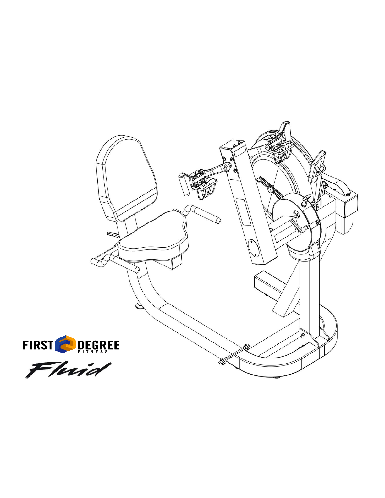
Owners Manual
E720

2 Contents
1. Contents of E720 Box.
2. E720 assembly instructions.
3. Tank filling and water treatment.
4. Long term water treatment and basic
operation.
5. E720 Control arm.
6. Maintenance.
7. Troubleshooting guide
8. The E720 Ergometer.
9. Tank belt drive adjustment.
10. Parts list and Warranty.
As with any piece of fitness equipment, consult a physician before
beginning your E720 exercise program.
CAUTION
Use two hands and follow all safety in-
structions whenever raising or lower-
ing the E720 control arm.
Warning
Do not remove feet or hands while crank is in motion. The crank
will continue to rotate and could cause injury.
Training with E720
3
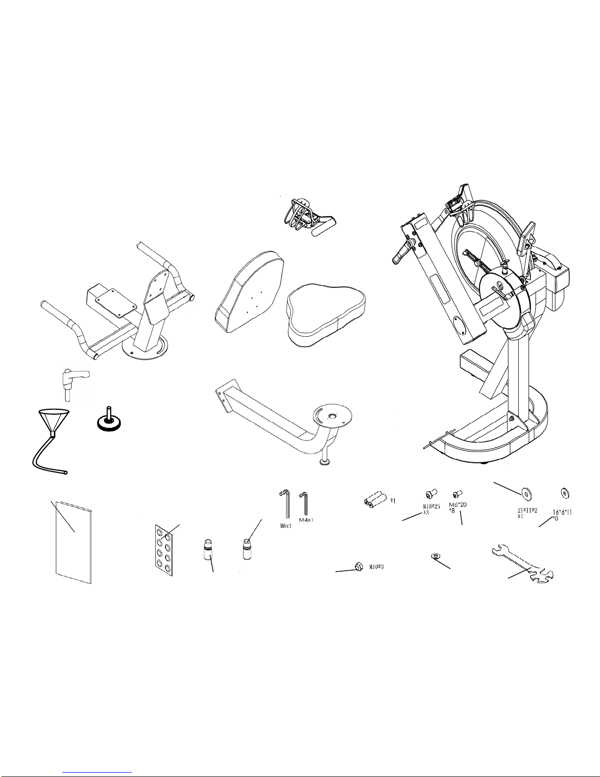
Box Contents
1x Upper seat frame
1x Main frame
1x Upper/Lower seat
frame
1x Lower seat frame
1x Right crank
pedal
1x L-pin
1x Fill funnel/hose
3x Leveler
Hex Keys 2x Batteries
3x Frame bolts 8x Seat bolts
7x Frame bolt washers
8x Seat bolt
washers
3x Main frame
Nylock nut 1x Multi-tool
M10 Plastic
Washer
Blue Dye
Owners Manual Touch Up
Paint
Chlorine Tab-
lets x 8
4
E720 Assembly Instructions
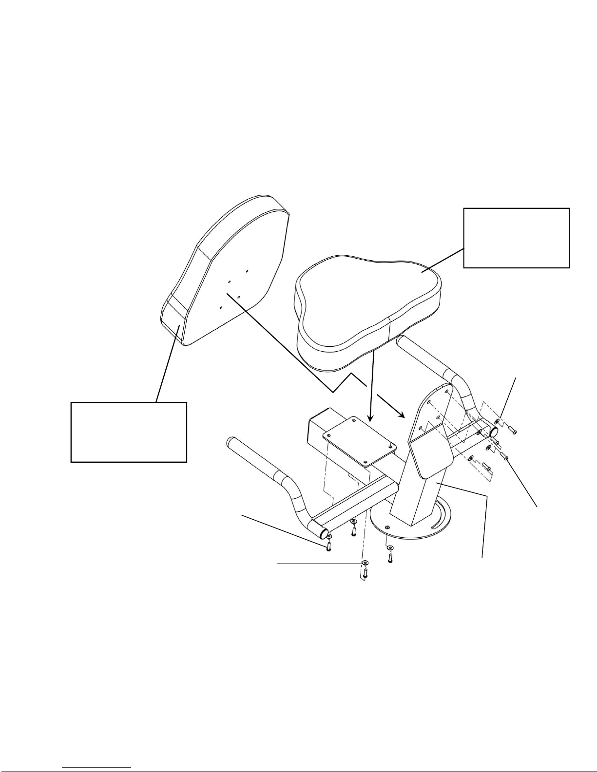
Upper seat
Lower seat
Step 1: Attach upper seat to
upper seat frame using 4x
M6x20mm bolts and 4x
16*6*l washers.
Step 2: Attach lower seat
to upper seat frame using
4x M6x20mm bolts and 4x
16*6*l washers.
Upper seat frame
M6x20mm bolt
M6*16*1 washer
M6*16*1 washer
M6x20mm bolt

5
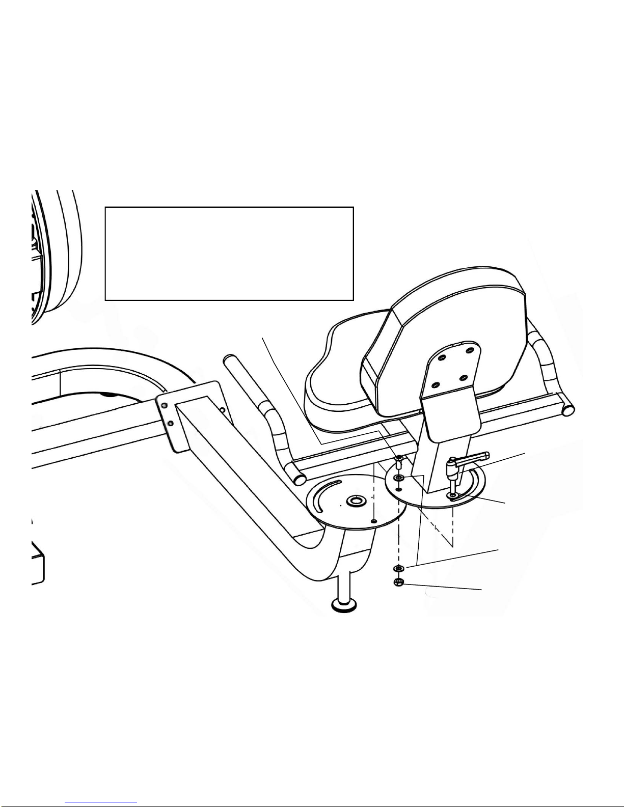
Step 3: Attach lower seat to lower
mainframe using 2x M10x25mm
bolts, 2x M10 Nylock nuts and 4x
21*11*2 washers
M10 Nylock nut
21*11*2 washer
M10x25mm bolt
E720 Assembly Instructions
6
L-Pin
M10x25mm bolt
M10 Nylock nut
21*11*2 washer
Step 4: Lower upper seat frame onto lower mainframe and
secure using 1x M10x25mm bolt, 1x M10 Nylock nut, 3x
21*11*2 washers and L-pin.
Note: Tighten the M10x25mm bolt, washers and Nylock until
lightly snug only. Over-tightening will prevent the seat from
rotating. Use the L-pin to tighten the upper seat frame once
rotated into place.
E720 Assembly Instructions
M10 plastic washer

7
Step 5: Secure right pedal onto Crank arm. The
pedal threads have a blue coating which will feel very
tight when threaded onto the crank arm. This is a
type of thread locker, and once in contact with the
crank arm threads will activate in approximately
15minutes.
Caution! Extreme over-tightening could damage the
aluminum threads on the crank arm.
Note: Allow 15 minutes for the
thread-locker to activate before
first time use.
Check pedal tightness on a regular
basis and tighten as needed with a
15mm wrench.
E720 Assembly Instructions

8
Note: A large bucket is required for filling (Not included)
In areas where tap water quality is known to be
poor, FDF recommends the use of distilled water.
Tank filling and water treatment
Open the rear upper yellow tank plug and insert hose into
tank (rotating the impeller slightly may be necessary to al-
low the hose to pass), move the tank adjuster handle to
level 20 and begin filling. Do not fill the tank higher than
the level indicator on the front of the clear shell. A prop-
erly filled tank holds approximately 8liters of water.
Warning: Do not under any circumstances put
fingers into the tank. Use the end of the hose to
move the impeller should the need arise.
Water Treatment Procedures:
1. Add Chlorine tablet.
2. Wait a minimum of 72 hours.
Then add very small amount of blue
dye and check for desired color. Im-
portant! Do not add blue dye for at
least 72 hours following Chlorine
treatment. The blue dye adds visual
appeal as well as cutting down the
amount of light affecting the tank water,
thus extending the amount of time be-
tween water treatments.
Note: The blue
dye is extremely
concentrated and
will readily stain
carpet or clothing.
Caution: Use a drop cloth when filling or
adding blue dye
Blue Dye
Yellow
tank plug
Filling hose
and funnel

9
CAUTION
Caution: It is important that a drop
cloth be used under the fluid tank whenever
the tank plug is opened for water treatment.
The level of resistance is deter-
mined by the level indicator located
on the front of the tank. Level one
indicates lightest resistance, level
twenty represents heaviest resis-
tance. Allow three to four seconds
after adjusting resistance handle for
the correct resistance level to be
achieved.
Long term water treatment:
Do not use any water treatment other than the tablets
supplied with this machine. For replacement tablets, con-
tact your local First Degree Fitness distributor.
Water treatment schedules for the E720 will vary according
to the fluid tanks exposure to sunlight, but expect 8-12
months near a bright, sunlit window and 2 years or more for
a darker location. At the point of finding the water slightly
cloudy, add a Chlorine tablet. Remember to wait 72 hours
following the chlorine tablet before adding the blue dye as
the Chlorine tablet is extremely concentrated.
Important: Do not fill past the calibration mark as indi-
cated on the tank level sticker or water spillage may occur.
See tank filling/water treatment page for details.
Long term water treatment and basic operation
Resistance:
Warning:
Use two hands when either raising or lower-
ing the control arm as pictured.
Removing hands or feet before the crank
comes to a complete stop while training can
cause injury. The crank is direct drive so as
to allow both forward and reverse rotation
during training.
10
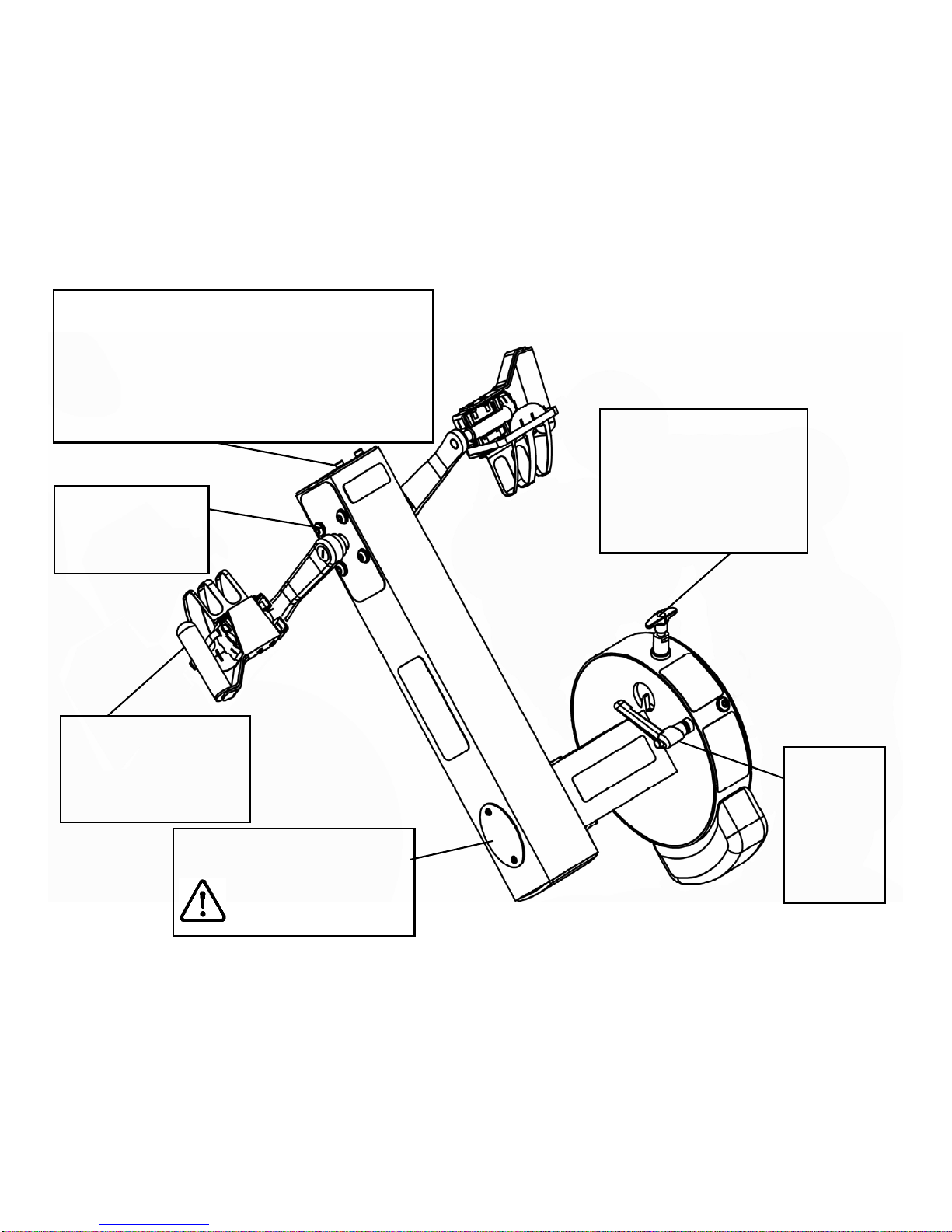
Chain tensioning bolts: Allows for tightening the chain or
adjustment from side to side. Make sure when tightening
only to adjust the same amount for both bolts, otherwise the
sprocket will be misaligned.
Note: Tightening the right bolt only will pull the right side of
the crank assembly toward you, tightening the left will pull the
left side toward you. Use this feature to realign the rear with
the front sprocket if needed or when changing to a new chain.
The E720 Pedal: This pat-
ented design allows for usage
in both the recumbent posi-
tion and for sitting/standing
upper body workouts.
L-pin: Loosen
when rotating
the control arm
and tighten
(snug only)
once the de-
sired position
has been
reached.
T-pin: The T-pin locks the con-
trol arm in any one of 72 different
positions throughout its 360 de-
gree range of motion. Pull up
the T-pin to allow the control arm
to rotate while supporting the
control arm with the other hand.
Crank arm bolts:
Loosen all 8 bolts
slightly before adjusting/
tightening chain.
The E720 Control Arm
Inspection plate: Open to check
chain tension.
Warning: Do not check
chain tension by hand!

11
Item Timeframe Instructions Notes
Seat and Frame. Weekly. Wipe down weekly with lint free
cloth or more often with heavy club
use.
PK belt tension. Monthly. Check monthly for signs of slippage.
Adjust/tighten as required.
Tank and water treatment. 12 months to 2 years. Follow instructions as specified in
the “Water Treatment” section of
this manual.
Chain drive. Check every 100 hours for correct
tension. Open the inspection plate and check
tension using a screwdriver or other
tool. Tighten as required using
chain tensioning bolts located at the
end of the control arm.
E720 pedals. Tighten weekly using 15mm box
wrench (supplied) The pedals should be checked on a
regular basis. A loose pedal can
cause damage to the crank arm alu-
minum threads, requiring replace-
ment.
Maintenance chart.

12
Fault Probable Cause Solution
Water changes color or becomes
cloudy. Rower is in direct sunlight or has
not had water treatment.
Change rower location to reduce direct exposure to sunlight.
Add water treatment and blue dye or change tank water as
directed in the water treatment section of this manual.
Knocking noise from inside the control
arm while training, especially when
changing directions.
Chain requires tightening or ad-
justment. Open inspection plate located on front of control arm and
check tension using a screwdriver or other tool. Use the
chain tensioning bolts located at the rear of the control arm
to tighten or adjust as needed. The chain should have
approx 3mm of slack when properly adjusted. See P.10 for
details.
Pedals slip during hard training. PK tank belt requires tightening. Remove large inspection plate next to the tank, insert a long
tool to push the rear end cap out from the inside, exposing
the tank belt tensioning bolt. Loosen tank bolts slightly. Re-
move upper rubber belt cover to expose the PK belt.
Tighten the tank tensioning bolt until the belt is too tight to
be twisted from side to side more than 45 degrees by hand.
See P.14 for details
Pedal is loose (either left or right) and
cannot be retightened. Aluminum crank arm threads are
stripped.
Contact service center for replacement. Then check weekly
as recommended.
Computer screen illuminates, but does
not register when rowing.
Loose or failed connection/
Sensor gap too wide (see erratic
computer display).
Check that the computer lead is connected properly. If con-
nected properly check sensor gap. Contact your local ser-
vice center if this fails to address the problem.
The E720 computer does not illuminate
after battery installation. Batteries installed incorrectly or
need replacing. Reinstall batteries in correct position and try again. If the
LCD screen fails to illuminate, try rotating the batteries
slightly in the computer. If this fails, contact your local ser-
vice center.
The E720 computer display is erratic/
slow while displaying RPM and WATTS Gap between sensor and mag-
netic ring is too wide. Remove inspection plate and check sensor gap and that
magnetic ring is not wobbly.
Troubleshooting guide:
13
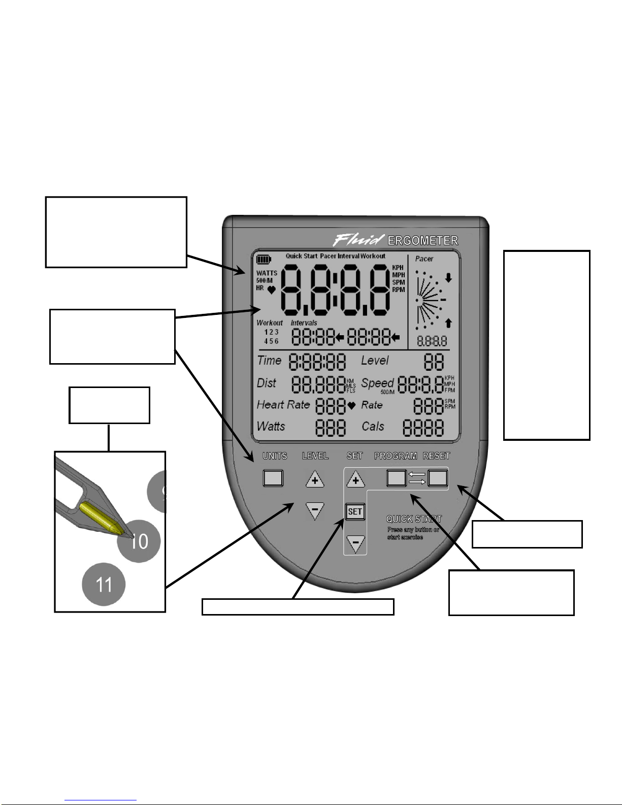
E720 Ergometer
Quick start provides instant
workout information. Just start
training to activate. You can
choose to change UNITS dis-
played.
UNITS displays
WATTS, RPM, HR, MPH,
Level Adjustable
from 1-20
Set Changes Time, Distance parameters
Program Clears current exer-
cise program
Note: For complete
operational instruc-
tions, please refer
to the computer
manual, which is
included with your
E720.
Reset Clears data
14
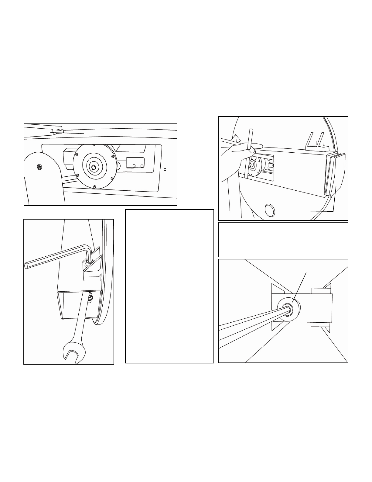
Step 1
Step 1: Remove large metal in-
spection plate as shown above
right.
Step 2: Using a long tool, push out
the rear end cap as pictured above
right. This will give you access to
the tank tensioning bolt (shown bot-
tom right).
Step 3: Loosen both the rear and
front tank bolts slightly as shown
left. Remove front rubber belt
cover.
Step 4: Using a 6mm Allen key,
tighten the belt using the tank ten-
sioning bolt until the belt no longer
slips during hard rowing.
Note: Do not over tighten tank
bolts.
Step 2
Step 3 Step 4
Tank Belt Adjustment
Tank tensioning bolt
End Cap
Rubber belt cover
Tip: Twist the belt by hand to gauge tightness. Cor-
rect tension should be obtained when no longer able
to twist more than 60 degrees.

15
P/N QTY Description
33100 1 Main Frame Assembly
20008 1 End Cap 75x75
10040 1 Bolt M12x140
10043 6 Washer M12
10066 3 End Cap 100x100mm
10067 2
Rubber Cover for Large PK
Pulley
10072 2
Small Steel Side Cover
100mm
10170 6 Washer M4
10070 18 Screw M4x10
20163 2 Semi Circle Cover
20850 1 Tension Adjustment
10082 5 Washer M10
10041 4 Nut M10 Nylock
71025 2
M10x25mm Main Shaft Rear
Bracket Bolt
10139 2 Spring Washer Flywheel Shaft
33915 1 Oil Bushing
23045 1 L Pin M10x35
33913 1 Plastic Spacer 10x25x4T
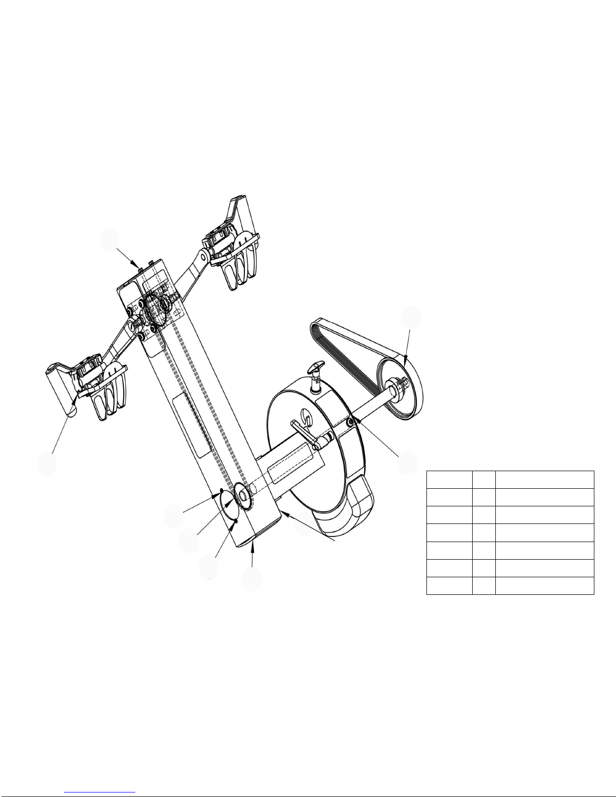
E720 Exploded Diagram:
10066
33100
10170
Refer to Control
Arm Assembly
Refer to A010
Tank Assembly
20850
Refer to Computer
Assembly
10040
10043
10067
20163
10070
10072
10082
10041
20008
71025
10139
33915
Refer to Seat Frame
Assembly
23045
33913
Refer to A037/A038
Left & Right Pedal
Assembly
Refer to Seat
Frame Assembly
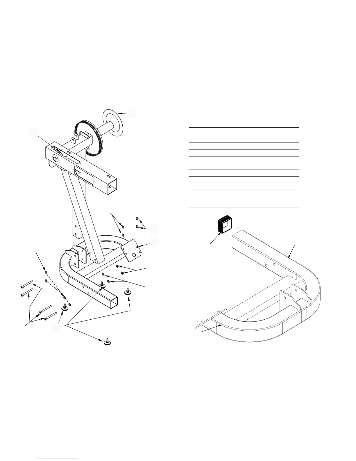
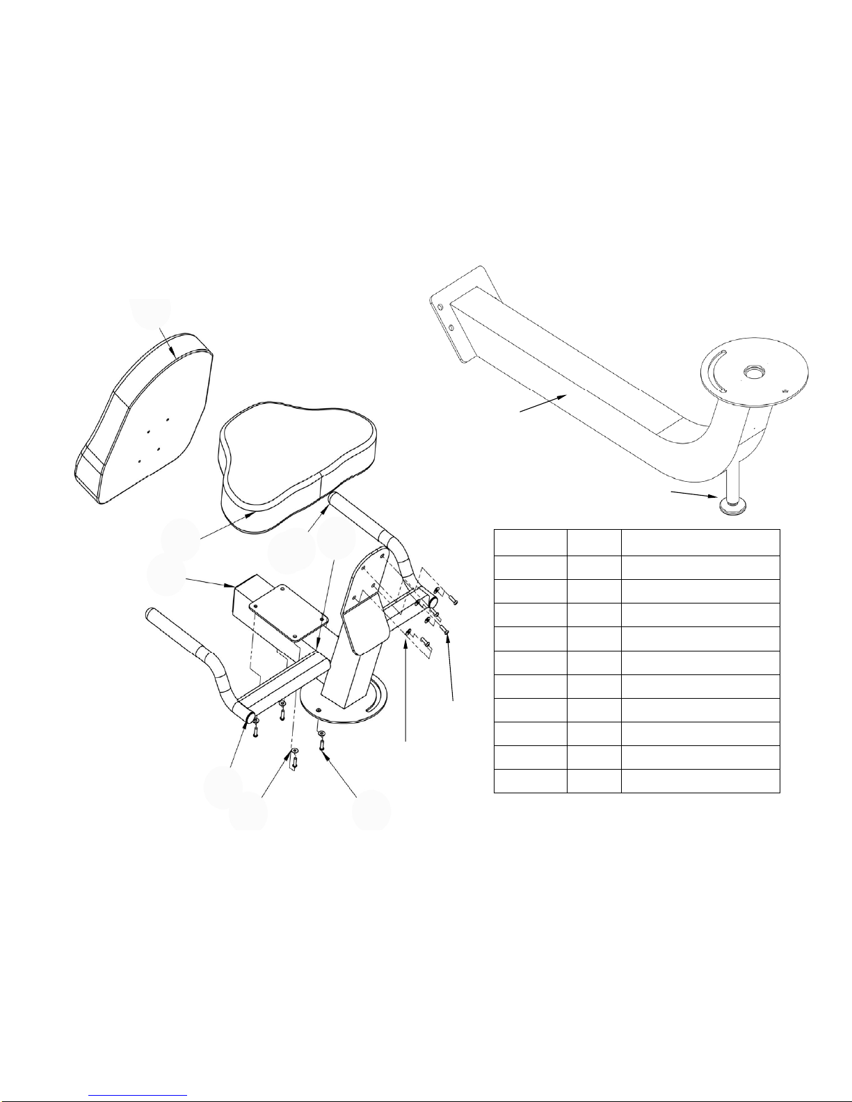
16 P/N QTY Description
20101 1 Upper Main Frame
10082 8 Washer M10
20024 1 Number Decal
33101 1 Lower Main Frame
73016 4 Foot Levelers M8x30 PVC
10041 4 Nut M10 Nylock
20009 4 Bolt M10x100
20014 1 Right Bottom Frame
30010 1 Left Bottom Frame
23008 1 End Cap 75x75 Rubber
20014
30010
10082
20024
33101
73016
20009
10041
20101
Upper/Lower Mainframe:
10041
10082
10082
23008
17
Refer to Crank Arm
Assembly
20850
20163
10066
Refer to Control Arm
Assembly
10170
30012
10070
Refer to Main Drive
Assembly
Control Arm (external) Assembly:
P/N QTY Description
30012 1 DID-25 Chain 178
10066 1 End Cap 100mm
10170 2 Washer M4
10070 2 Screw M4x10
20163 2 Semi Circle Cover
20850 1 Tension Adjustment
18
10080
10081
30014
20008
33910
30002
20115
20117
10080
10081
P/N QTY Description
20115 1 Seat LS-622
20117 1 Seat Back LS-622
10080 8 Bolt M6x20
10081 8 Washer M6
20008 1 End Cap 75x75 PVC
30014 2 End Cap
30002 2 Handle Grip
33910 1 Rotating Seat Frame Upper
73016 1 Foot Levelers M8x30 PVC
33902 1 Seat Lower Frame
73016
33902
Seat Frame Assembly:

19
P/N QTY Description
13112 1 Computer Mounting Arm
10114 4 Bushing 20x16x13x10
10082 4 Washer M10
10116 1 Bolt M10x60
10097 2 Nut Dome Head M10
10117 1 Computer Wiring 1200
10096 1 Bolt M10x70 for Aluminum Rail
30903 1 Computer
30903
10096
10117
10097
10116
10082
10114
13112
10114
10082
20068
10083
10041
20125
20045
30013
20170
10083
10082
20151
20020
20151
20064 20174
20151
10120 20170
20170
20170
20151
20032 20033
20036
20291
Computer Assembly
P/N QTY Description
20291 1 Rotating Arm
20064 1 Weight Block
10083 2 Bolt M10x20
20151 4 Washer M10
20020 1 Bolt M10x35
10082 1 Washer M10
20174 1 Eccentric Bushing
10041 1 Nut M10 Nylock
10120 1 Screw M6x15
20125 1 Plastic Washer 30*6*6
20068 1 T-Pin
20045 1 L-Pin M12x40
20170 4 Chain Protection Decal
30013 1 CXT Decal
20032 1 Warning Decal
20033 1 Arm Moving Decal
20036 1 Small Warning Decal Control Arm Assembly
20
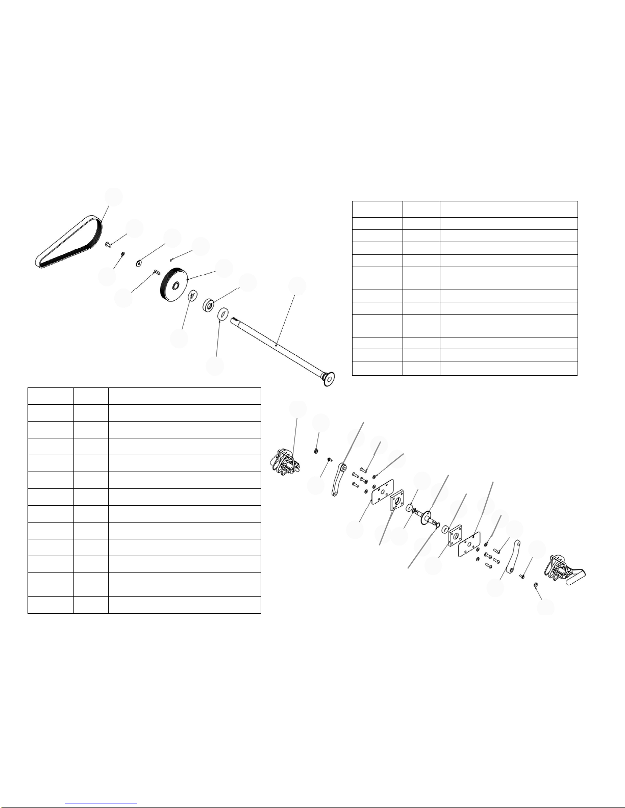
P/N QTY Description
20157 1 Shaft+Sprocket
10146 1 Ball Bearing NSK6006ZZ
10011 1 Bearing Housing
10012 1 NSK 6005ZZ Bearing
10015 1
Large PK Transmission Pulley
150mm
10017 1 Key way 7x7x32
10052 1 Grub Screw M4x6
10138 1
Shaft Washer 30x10.2x3t for Fly-
wheel, Stainless
10139 1 Spring Washer M10 for Impeller
10109 1 Belt 7PK 926mm HUTCHINSON
10083 1 Bolt M10x20
P/N QTY Description
30611 1 Right Pedal Assembly
30610 1 Cycle Axle + Cog
20052 2 Side Bearing Cover
10082 8 Washer M10
20020 8 Bolt M10x35
20134 1 Crank-Left
20135 1 Crank-Right
20132 2 France Screw M8x20xP1.0
20133 2 Crank End Cap
20190 2 Aluminum Block Bearing Housing
20193 2
NSK 6004ZZ Aluminum Block Hous-
ing Bearing
20196 2 Wave Washer 20mm
10083
10109
10139
10138 10052
10017
10015
10012
10011
10146
20157
Main Drive Assembly
20133
30611
20135
30610
20196
20193
20190
20052
20020
10082
20132
20134
20196
20193 20052
20190
20020
10082
20132
20133
Crank Arm Assembly
Table of contents
Other First Degree Fitness Equipment manuals

Popular Fitness Equipment manuals by other brands

BERGER
BERGER VP Body Slim Manual instruction

Gratz Pilates
Gratz Pilates HALF CADILLAC CONVERSION Assembly instructions

Keys Fitness
Keys Fitness Leg Press Hack Squat KF-LPHS owner's manual

Stamina
Stamina 1690 POWER TOWER owner's manual

TKO
TKO 823NVR-SM owner's manual

York Fitness
York Fitness 45072 owner's manual


