First Office HEIGHT ADJUSTABLE TABLE User manual

1. Panel
2. Initialization Procedure
The initalization procedure must be completed before the first running table after the
table is installed or parts replaced.
• Press and Hold & simultaneously for more than 3 seconds, the legs begin to move
down at half speed of normal operation.
• Keep pressing the & , notice the legs move down to the lowest position and rebound
2-5 mm, then stop.
• Then release & together, the initialization process is complete.
3. Move Up & Down
• Press and Hold and the legs move up.
• Release and the legs stop.
• Press and Hold and the legs move down.
• Release and the legs stop.
4. Set Memory Positions
• Press and Hold & , then release and run the legs to the position you want the table surface to be.
• Click button S, and then click button 1 , 2 , or 3 within next 3 seconds, this is how you save the positions.
5. Move to the Memorized Positions
• Press and hold the button 1 , 2 , or 3, and the legs will return to corresponding positions saved.
6. Verify the Display Switch Data to Table Height
Check the switch display format in inches or centimeters and toggle to the unit you like and match
to the actual measurement. In inches format, the minimum adjustable height is 0.5 inches, while in
centimeters format is 1 centimeter.
• Set the table at any height (reccommended at the bottom position), measure the table actual height
and write down the number in inches or in centimeters.
• Press and Hold the button S, then press and hold , keep for about 3 seconds. The first number should
start flashing on the screen.
• Release the buttons and click on either or to change the first number. The first number is being
increased or decreased to the first number you measured.
• Click button S and the second number should start flashing on the screen.
• Click or to change the number, the second number is being increased or decreased to the second
number you measured.
• Click button S, the third number should start flashing on the screen.
• Click or to change the number, The third number is being increased or decreased to the third
number you measured.
• Click button S, completed.
DIGITAL HANDSET OPERATION
OPERATION INSTRUCTIONS
RANGE INSTRUCTION SHEET #2577INS
PART #1730534
• 1 Button: Preset 1
• 2 Button: Preset 2
• Display: Reads in 1/2" Increments
• 3 Button: Preset 3
• S Button: Select

HEIGHT ADJUSTABLE BENCH KIT
ASSEMBLY INSTRUCTIONS
RANGE
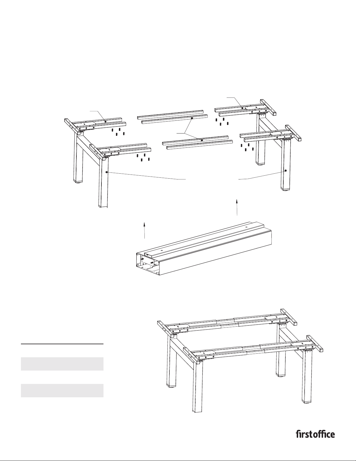
1. Attach cross tubes A & B and the strut tube to the leg
column by inserting the plastic screw guides into the
mounting holes and securing with (2) m6x15 machine
screws per tube.
2. Repeat step 1 to complete 4 leg assemblies.
INSTRUCTION SHEET #2576INS
PART #1730533
1
3. With 2 leg assemblies and 1 cross bar
assemble one half of the bench.
Note: make sure the inserts of the cross
bar face toward the kneespace.
4. Slide cross bar over mounting tab on leg
assembly and attach using supplied bolts.
2 Bolts per leg.
Note: make sure cross bar is seated
square and flush with leg assembly. And
bolts are tight. Loose connections will
aect the stability of the bench.
5. Repeat steps 3 & 4 to complete the other
half of the bench assembly.
CROSS TUBE A
CROSS TUBE B
LEG ASSEMBLY
STEPS 1-2
HEIGHT ADJUSTABLE
LEG COLUMN
STRUT TUBE
HALF BENCH ASSEMBLY
STEPS 3-5
LEG ASSEMBLY
MOUNTING
TAB
CROSS BAR
NOTE: INSERTS FACE
TO KNEE SPACE
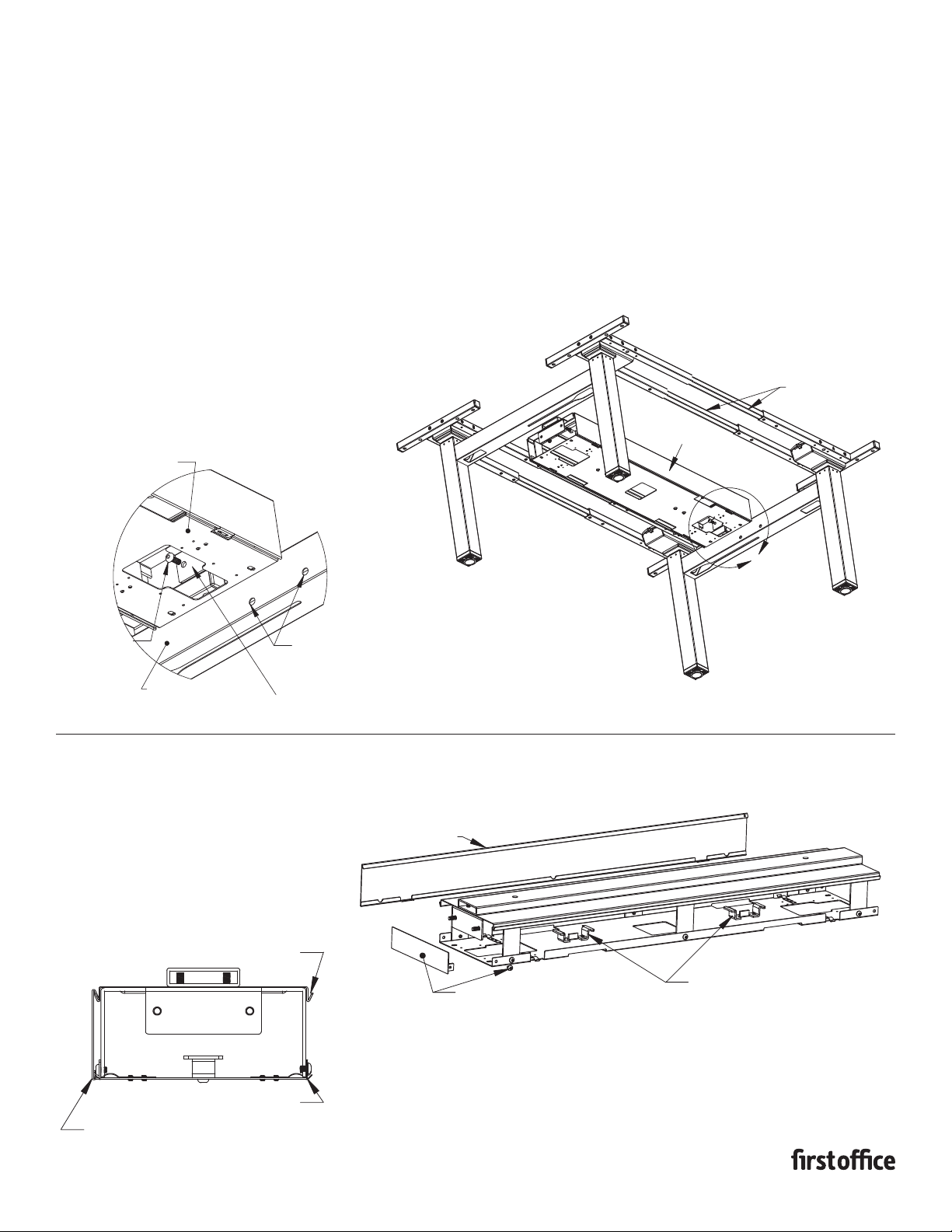
6. Insert spanner bars into cross tubes of one bench assembly
half with notch facing downward and secure with m10x25 set
screws. (See chart for Spanner Bar insertion depth)
7. Slide the other bench assembly half onto the spanner bars.
If no cable carrier needs installed tighten remaining set
screws and bench assembly is compelte. If cable carrier is to
be installed leave second bench assembly half loose for final
adjustament and refer to cable carrier installation guide.
SPANNER BARS
CROSS TUBES
CROSS TUBES
BENCH ASSEMBLY HALF
BENCH
SIZES
SPANNER
BAR DEPTH
54 12.75"
60 9.75"
66 6.75"
72 3.75
INSTRUCTION SHEET # 2576INS
2
CABLE CARRIER
CABLE CARRIER
ASSEMBLY INSTRUCTIONS
CABLE CARRIER
EXTRA FEATURES
RANGE
1. Adjust the benching frame assembly to have a distance
between cross bars slightly larger than the width of the
cable carrier. Leave one end of the spanner bars loose
for final adjustment.
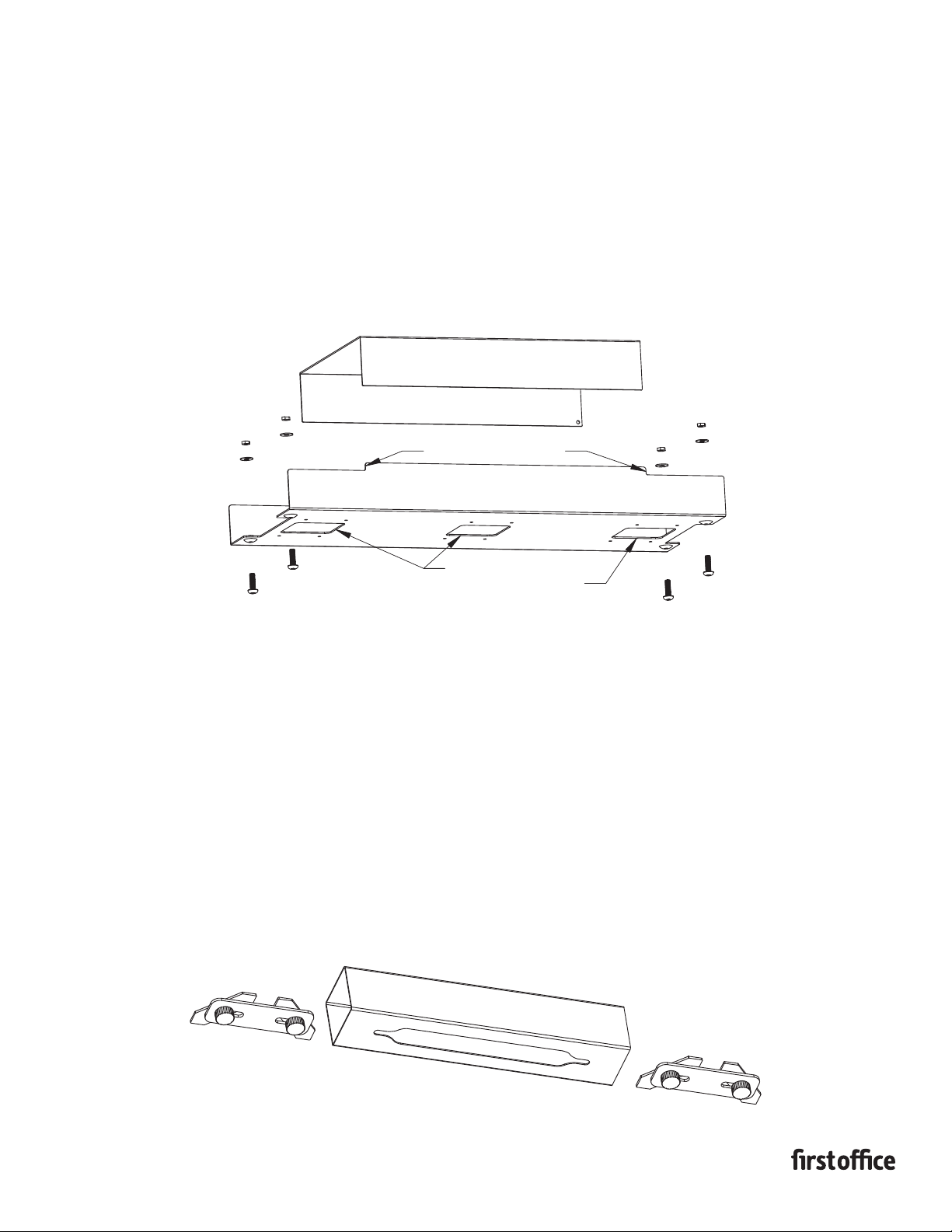
2. Attach the cable carrier to the cross bars using (4) M8x20
bolts through the inside of the cable carrier mounting
L-bracket and into the insert nuts in the side of the benching
cross bars.
3. Once the cable carrier is secured to the benching cross bars
tighten the remaining spanner bar set screws.
INSTRUCTION SHEET # 2575INS
PART #1730532
A
SPANNER BARS
CABLE CARRIER
NOTE: ILLUSTRATION SHOWN
FROM UNDERNEATH
DETAIL A
SCALE 1 : 4
(4) M8x20
MACHINE SCREW CROSS BAR INSERT NUT
MOUNTING L BRACKET
BENCHING CROSS BAR
CABLE CARRIER ASSEMBLY
A
LOWER SPRING CLIP
UPPER HANGING LEDGE
TO REMOVE PULL OUTWARD AT BOTTOM EDGE
TO RELEASE THE SPRING CLIP AND LIFT UPWARD
TO REMOVE FROM THE HANGING LEDGE
REMOVING THE ACCESS PANELS
PRE-ASSEMBLED ELECTRICAL
BRACKETS TO ATTACH POWER BLOCK
REMOVABLE ACCESS
PANEL BOTH SIDES
END CAP SLIDES INTO END
OF CABLE CARRIER & ATTACHES
WITH (2) M6X8 MACHINE SCREWS
GANGING TRAY
ASSEMBLY INSTRUCTIONS
RANGE
1. Insert end of ganging tray into open end of cable carrier of bench until it stops
againts the built in spacing ledge.
2. Attach with (2) m4x20 bolts inserted from bottom side through mounting holes
and secured with washer and nut from top side. Note: do not over tighten bolts.
3. Slide next bench into position inserting the other end of the ganging tray into the
end of the cable carrier up to the spacing ledge and secure repeating step 2.
INSTRUCTION SHEET #2578INS
PART #1730535
GANGING RAIL
ASSEMBLY INSTRUCTIONS
RANGE
1. Insert one end of each thumb screw bracket into slot in bottom of rail and
turn thumb screw to tighten. Leave loose for adjustment until benches are
in final position.
2. Insert opposite end of one of the thumb screw brackets in the slot in the
bottom of the benching cross bar. Once rail is centered in and flush to
side of cross bar tighten the thumb screws to secure rail to bench.
3. Move the next bench in place tight up against the ganging rail, positioning
the rail centered and square to the benches cross bar and attach with the
tumb screw bracket.
REMOVABLE ACCESS PANEL
(LIFT OFF TO REMOVE)
3 CABLE ENTRY POLE
ATTACHING LOCATIONS
BUILT IN SPACING LEDGE
This manual suits for next models
11
Table of contents
Other First Office Indoor Furnishing manuals


Popular Indoor Furnishing manuals by other brands

Regency
Regency LWMS3015 Assembly instructions

Furniture of America
Furniture of America CM7751C Assembly instructions

Safavieh Furniture
Safavieh Furniture Estella CNS5731 manual

PLACES OF STYLE
PLACES OF STYLE Ovalfuss Assembly instruction

Trasman
Trasman 1138 Bo1 Assembly manual

Costway
Costway JV10856 manual


