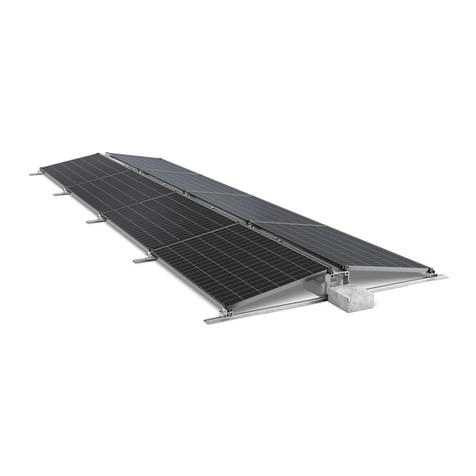
TOLEDO SOLAR TS2-WS User manual

User Guide:
Toledo Solar TS2-WSModule
North America
User Guide
REV 0.0
TS2-WS Module User Guide—North America | 1 of 18

Table of Contents
1 Introduction...................................................................................................................................................................3
1.1 Before You Begin..............................................................................................................................................3
1.2 Key Product Features .......................................................................................................................................3
1.3
Safety ...............................................................................................................................................................4
2 Regulatory Compliance..................................................................................................................................................5
3 ElectricalSpecifications .................................................................................................................................................6
3.1 SystemDeratingFactors...................................................................................................................................6
4 Installation .....................................................................................................................................................................7
4.1 Mounting..........................................................................................................................................................7-8
4.2 ModuleOrientation .........................................................................................................................................9
4.3 ModuleShadingConsiderations.......................................................................................................................9
4.4 ElectricalInterconnection ................................................................................................................................10-12
5 MechanicalSpecifications&Drawings.........................................................................................................................13
6 ProperOperatingConditions .......................................................................................................................................14
7
Service .........................................................................................................................................................................15
8 WarrantyTerms&Conditions......................................................................................................................................15
9 Notice ..........................................................................................................................................................................16
10 Document References..................................................................................................................................................17
11 Revision History ...........................................................................................................................................................18
TS2-WS Module User Guide—North America | 2 of 18

1 Introduction
Toledo Solar TS2-WSModules are manufactured in state-of-the-art facilities using ahighly innovative process that rapidly
deposits thin films of semiconductor on glass. The modules have been designed to have along operating life and high en-
ergy yield when installed, operated, and serviced in accordance with the instructions in this User Guide.
1.1 Before You Begin
ThisdocumentprovidesguidelinesandinformationonToledoSolarTS2-WS modulesofmodelforsystem
designers, installers, andmaintenancepersonnel. ReadthisUserGuidethoroughlybeforebeginninganyworkrelatedtothe
installation, operation, or maintenance of the Toledo Solar TS2-WS.Only qualified personnel should install, operate, or main-
tain aPV module or system.
Failuretofollowinstallationandhandlinginstructionsmayresultininjury.
Failuretomaintainproperoperatingconditionrequirementsforthemoduleswillvoidtheapplicablewarranties.
ThisuserguidepertainstomodulesinstalledwithinNorthAmericaonly.IfamoduleisbeinginstalledoutsideofNorth
America,contactToledoSolar(info@toledo-solar.com)fortheUserGuideappropriate forother geographic areas.
Keep this User Guide for future reference.
Guidelinesrelatedtosystemconstructionarebeyondthescopeofthisdocumentandarenotcoveredinthisdocument.
1.2 Key Product Features
• Highenergyyieldsinreal-worldcondions.
• Sizeandweightthatenablesecienthandlingandinstallaon.
• Easy,quick-connectwiringforfastinterconnecon.
• Compablewithadvanced1500Vplantarchitectures.
• Internaonallyrecognizedproductcercaons.
• Thirtyyearlimitedperformancewarranes.
TS2-WS Module User Guide—North America | 3 of 18

1.3 Safety
The TS2-WSModules may produce voltage up to 110 Volts DC (VDC) or current up to 3.0 Amps when exposed to
sunlight. A single module could create a lethal shock hazard during hours of daylight, including periods of low
light levels. The danger increases as modules are connected together in series and/or parallel.
To avoid fire and/or injury due to ground fault and associated electrical hazards:
• Do not unplug PV module connecons while under load. Do not disconnect the module connectors
during daylight hours unless the module is in an open circuit condion or all modules in series and
parallel are covered with an opaque material, such as a tarp or blanket.
• Repair or replace damaged wires immediately. Keep all array wiring out of reach of non-qualied
personnel.
• Do not concentrate light on the module in an aempt to increase power output.
• Never allow the PV array system voltage to exceed 1500VDC under any condion.
• Replace broken modules immediately.
• Repair any ground faults immediately.
• Do not work on modules or systems when the modules or wiring are wet.
Reverse currents higher than the rated values for a Toledo Solar module (reverse current overload), may result
in module failure, including module breakage. Extreme and continuous reverse current overload conditions
may cause a fire or create electrical shock hazards. To avoid reverse current overload:
• Maintain equivalent voltage in parallel strings by installing an equal number of modules per string within
the same source circuit. Failure to install modules with balanced voltage in parallel strings can result in
voltage imbalance.
• Comply with all pracces as stated in this document and repair ground faults.
It is the responsibility of the PV system installer to ensure compliance with all local building codes. As a minimum
level of protection, all building mounted PV systems should utilize Ground Fault Circuit Interrupters and Arc Fault Circuit
Interrupters to minimize risk of electrcal shocks and fires.
Wear safety glasses (ANSI Z87.1-2003) and cut-resistant gloves when working on non-interconnected modules or
systems. Wear electrically rated PPE when working on interconnected modules or system components.
TS2-WS Module User Guide—North America | 4 of 18

2Regulatory Compliance
Itistheresponsibility oftheinstallerand/orsystemintegratortoensurecompliancewithalllocalelectricalcodes whichmay
beapplicabletotheinstallationanduseofToledo Solar Suite Modules.
•BeforebeginningthePVsystemdesignandinstallaon,contactappropriatelocalauthoriestodeterminelocal
code,permit,andinspeconrequirements.
•ForsystemsinstalledinCanada,installaonshallbeinaccordancewithCSAC22.1,SafetyStandardforElectrical
Installaons,CanadianElectricalCode,Part1.
Toledo SolarTS Suite ModulesareListedbyaNationallyRecognizedTestLaboratorytoUL61730,thestandardforFlat-
Plate Photovoltaic Modules and Panels.
Tomaintainthemodules’applicaonasaULListedproduct:
•UseonlycomponentsthathavebeenRecognizedorListedbyUnderwritersLaboratories(UL)fortheirintended
purpose.
•EnsurethePVarrayopen-circuitvoltagedoesnotexceed1500VDC(1000VDCforULCanada).
•InstallmoduleswithmountingsystemsthathavebeenevaluatedforULListedapplicationasspecifiedinToledo
Solar ApplicationNoteTSI-PD-400-04 NA.
•ProtectmodulesfromreversecurrentsinexcessoftheMaximumSeriesFuseratingof4.0A.
WhenusingMC4 connectors,TS2-WS Modules meet the requirements of ProtectionClass IIfor 600VDCsystemsand
ProtectionClass0for1000VDCsystems.WhenusingMC4-EVO2connectors,TS2-WSModulesmeettherequirements
ofProtectionClassIIfor1000VDCand1500VDCsystems.TS2-WS ModulesaretestedandcertifiedperIEC61730with
maximumovercurrentprotectionratingsof4.0A.TS2-WS ModulesaretestedandcertifiedperIEC61646/IEC61215for
amaximumsystemvoltageof1000V.
TS2-WS Module User Guide—North America | 5 of 18

3 Electrical Specicaons
1.Class A Spread of Flame / Class CBurning Brand. Roof mounted fire rating is established by assessing rack and solar module as a unit
2.Limited power output and product warranties subject to warranty terms and conditions
3.Ensures 98% rated power in first year, -0.5%/year through year 30
4.All ratings ± 10%, unless specified otherwise. Specifications are subject to change
5.Measurement uncertainty applies
6.Application Class A for 600V (class II), Application Class B for 1000V (class 0) with MC4; Application Class A for 600V and 1000V (class II) with MC4-EVO
7.Multi-Contact: MC4 (PV-KST4/PV-KBT4) MC4 EVO 2 (PV-KST-EVO 2 / PV-KBT-EVO 2).
8.Higher load ratings can be met with additional clips or wider clips, subject to testing
3.1 SystemDerangFactors
Undernormaloperaon,aphotovoltaicmodulemayexperiencecondionsthatproducemorecurrentand/orvoltagethan
reportedatStandardTestCondions.Accordingly,thedatasheetandlabelspecicaonvalueslistedforSTCshouldbe
mulpliedbyafactorof1.25forvoltageandcurrentwhendeterminingcomponentrangs.Adjustmentsofthosefactors
mightbeneededtorespectsitespecicclimatecondions.AsdenedintheNaonalElectricCodeandIEC62548,the
maximumsystemvoltageforaPhotovoltaicSystemisdeterminedusingtheopencircuitvoltageofthePVmodules.
Module Name TS2-105 TS2-110 TS2-115 TS2-120
Test Condition STC NOCT STC NOCT STC NOCT STC NOCT
Maximum Power (Pmp, W) (-
0/+5W) 105.0 78.9 110.2 82.4 115.0 85.9 120.0 89.9
Voltage @ Max Power (Vmp, V) 66.2 62.1 67.5 63.4 69.3 64.6 70.8 66.6
Current @ Max Power (Imp, A) 1.59 1.27 1.63 1.30 1.66 1.33 1.69 1.35
Open Circuit Voltage(Voc, V) 78.0 73.8 78.6 74.3 79.1 74.8 79.6 75.2
Short Circuit Current (Isc, A) 1.82 1.59 1.83 1.60 1.83 1.60 1.87 1.60
Maximum System Voltage 1000 V
Safety Class Class 0
Application Class Class B
Fire Rating Type 3
Temperature Coefficient of Pmpp -0.28% / ºC(from 25º Cto 75º C)
TemperatureCoefficient of Voc -0.28% / ºC
Temperature Coefficient of Isc +0.04% / ºC
Efficiencyat 200W/m22% greater than efficiency at 1000 W/m2
Normal Operating Cell Temperature(NOCT) 45ºC
Limiting Reverse Current (IR)4A
Maximum Source Circuit Fuse (ICF)4A
TS2-WS Module User Guide—North America | 6 of 18

4 Installaon
4.1 Mounng
Physically damaged modules may cause ground faults and associated electrical hazards. To avoid these
condions:
Do not install the modules during high wind or wet condions to reduce the likelihood of injury.
Wear safety glasses (ANSI Z87.1-2003) and cut-resistant gloves when working on non-interconnected modules or
systems.
Wear electrically rated PPE when working on interconnected modules or system components.
• Handle modules with care during installation, as heavy impact on the front, back, or edges could result in damage
to the module. Do not walk or stand on modules or retaining clips.
• Do not stack or carry multiple modules on top of one another after removal from factory packaging to minimize
the risk of breakage.
• Do not lift or pull on modules using lead wires to minimize the risk of wire damage.
MountingoftheTS2 Moduletoasuitablestructurecanbedonebyattachingthemoduledirectlytothestructureusing
retainingclips(seeFigure5.1.
Anymodulewithoutaframe(laminateshallnotbeconsideredtocomplywiththerequirementsofUL1703unlessthe
moduleismountedwithhardwarethathasbeentestedandevaluatedwiththemoduleunderthisstandardorbyafield
inspection certifying that the installed module complies with the requirements of UL 61730.The TS2-WS Module is aframe
less laminate and is considered to be in compliance with UL 61730 only when the module is mounted usingapprovedhard-
wareinthemannerspecifiedbythemountinginstructionsinToledo SolarApplicationNoteTSI-PD-400 04.
Additionalmountingsystemsmaybeapprovedforuse.Theinterfaceofthemountingstructuretothemodule(including
theretainingclipandrubberinsulator)mustmeetthetechnicalrequirementsspecifiedinToledo SolarApplicationNoteTSI-
PD-400-04andmustbeapprovedforusebyToledo Solarpriortoinstallation.Themountingsystemdesignmustprovide
adequatesupportforthemoduletopreventdamagefromoccurringwhenthemoduleissubjectedtopressuresof2400Pa
(whichequatestowindpressureof130km/h(80.8mph),withasafetyfactorof3forgustyconditionsbasedonIEC61646/
IEC61215).Thelocationoftheclipsshallbealongthe1200mm(47.25in)lengthofthemoduleandthecenterpointofthe
clipshallbelocatedbetween250mm(9.84in)and300mm(11.81in)fromthemoduleedge.SeeFigure5.1forallowed
location.Rubberinsulatormaterial,orequivalentmustbeusedbetweenthemoduleandboththeclipandmounting
structuretoprovideadequateprotectionofthemoduleandmustmeetallrequirementsdescribedinTSI-PD-400 TSI
ModuleMounting.Clamps must be bolted with a torque of 50 in.-lbs. Nodirectcontactofrigidstructuresispermitted
againstthesurfaceoredgesofthemodule.
Allmountingstructuresmustprovideaflatplaneforthemodulestobemountedon,andmustnotcauseanytwistorstress
tobeplacedonthemodule.
Modulesshouldnotbeinstalledinawaythatrestrictsaircirculationtotheundersideofthemodule.Modulesgenerate
heatandrequireadequateairflowforcooling.
!
!
!
!
TS2-WS Module User Guide—North America | 7of 18

Installationlocationsandmodulesupportstructuresshouldbeselectedtoensuremodulesandconnectors(openormated)
areneversubmersedinstandingwater.Toledo Solarmodulesaretestedandcertifiedforapplicationsinvolvingpressures
fromsnow/ice/windupto2400Pa(50.13lb/ft2)whenmountedproperly.Snowdriftscouldresultinanonuniformloading
ofthemoduleswhichexceedsthetestedpressure.Ifitisexpectedthatloadswillexceed2400Pa(50.13lb/ft2),
itisrecommendedtoclearsnowfrommodules,andensurethatice/thaw/freezecyclesundersnowdrisdonotresultin
excessive stresses on the module.
Heavyconstruconandtrenchingshouldbecompletedpriortomoduleinstallaontominimizedebrisanddust.
Ensureanysitepreparaonormaintenancechemicals(soilbindingagentsorchemicalsusedforon-sitedustcontrolorweed
control)donotspray,splash,ordriftontothesurfaceofthemodulesoritsassociatedcomponents.
TheULapproveddesignloadofTS2-WS Modulesis30lb/ft2(1436Pa).
Maximumallowablepressureonmodulesmaynotexceed2400Pa(50.13lb/ft2)withoutadditionalmodulesupportthat
mustbetestedandapprovedbyToledo Solartoreceiveaprojectspecificapproval.
Forrooopmounng,modulesmustbemountedoverareresistantroofcoveringratedfortheapplicaon.The
recommendedminimumstandoheightis3.25in(82.55mm).ModulesusedinULListedrooopapplicaonsmustbe
installedwithapprovedmounngsystems.Ifalternatemounngmeansareemployed,thismayaecttheLisngreclass
rangsandaddionalULretesngmayberequired.Thererangofthismoduleisvalidonlywhenmountedinthe
mannerspecifiedinthemechanicalmountinginstructions.
TS2-WS Module User Guide—North America | 8of 18

4.2 ModuleOrientaon
PVperformancemodelingsowareshouldbeusedtodeterminetheopmumorientaonandltangleforeachlocaon.
Forltedfree-eldapplicaonsorsingle-axistrackerapplicaonswherethereisrowtorowshading,modulesshallbe
installedinlandscapeorientaon.
4.3 ModuleShadingConsideraons
Tomaximizeperformance,modulesshouldbelocatedinanareathatreceivesdirectsunlightfrommid-morningtomid-
aernoon(typically9:00a.m.to3:00p.m.).Installaonmustavoidlocangthemoduleswhereshadowsmaybecausedby
buildings,trees,etc.
Specicshadingpaernscancausedamagetomodulecellsduetothecreaonoflocalizedareasofreversebias.Reverse
biasisgeneratedbyoneormoreseries-connectedcellsbeingshadedwhiletherestofthecellsarefullyilluminated.When
shadinggeometryissuitablefordamagetooccur,itcanhappeninveryshortduraons(secondstominutes)andundera
widerangeofirradiance(aslowas160W/m2).Anexampleofprohibitedshadingorientaonispresentedbelow.
Thereisnoriskofmoduledamagedueto“row-to-row”shadinginlandscapeorientaon.Thereisalsonoriskifshading
occurswhilemodulesareinopencircuitcondionsornoriskfromdiuseshadingforobjectsgreaterthan2metersor7
feet.
Thereisariskofmoduledamageduetoshadingfromwalkingorstandinginfrontofoperatingmodulesorfromparkingor
drivingvehiclesinfrontofoperatingmodulesduringilluminatedtimes.Bestpracticeistostayclosetothebacksideofthe
adjacentrackasonetravelsdownarowofoperatingmodules.
InstancesofshadingthatwillleadtoavoidedwarrantyincludetheHighRiskitemslistedbelow.
High Risk (Prohibited) Shading
1. Restingoradheringslenderobjects(tools,brooms,clothing,wires,tape)onsunnysideofoperatingmodules,orwhen
nearerthan~5-7feetaboveoperatingmodules,especiallywhenshadoworientedparalleltocells.
2. Fixedobjectswithin~5-7feetaboveoperatingmodulesthatcastashadowoverthelongdimensionofthecells.Close
objectslikeposts,ropes,signs,fences,orequipmentcanbegintoincreaseriskofpartialshadingoffullcellswhen nearer
than~5-7feetfromthesunny-sideofoperatingmodule.
3. Asupportframeormountingmethodontheshortedge(s)ofmodulesthatfullyshadestheentirelengthofacell(either
partiallyorcompletely).
4. Workingcontinuouslywithoutstretchedarmsortoolsoveroperatingmodules.
5. Cleaningapparatus,includingcleaningrobotsandothermechanismsthattraversethemodulerepeatedlywhilethe
systemisoperating(unlessevaluatedandapprovedbyToledo Solar).
TS2-WS Module User Guide—North America | 9 of 18

4.4 ElectricalInterconnection
Toledo SolarModulesarepre-configuredwithindustrystandardconnectors thatare“touchproof”withallliveparts
protectedagainstaccidental contactandprotected againstpolarityreversal.Thecables andMC4connectorsareUVand
weatherresistantfrom–40°Cto+85°C,andratedfor 1500VDCand22.5A(minimum,beforederatingforambient
temperature).The cablesand MC4-EVO2connectorsareUVandweatherresistantfrom–40°Cto+85°C, andrated for
1500VDCProtectionClassIIapplicationsand39A(ambienttemperature).
Modules with different TS Suite desginations (i.e. SS(LV) vs. WS(HV) have significantly different electrical
operating characteristics and should not be interconnected within the same inverter or MPPT to prevent power
output loss and voltage imbalance conditions that may create the risk of reverse current overload.
Damaged wires, connectors, or juncon boxes may cause ground faults, and associated electrical hazards,
including electrical shock. To avoid these condions:
•Protect unmated connectors from dust and moisture by using sealing caps (not provided, available from connector
manufacturer).
•Limit module connectors to 10 or fewer plug cycles.
•Do not pull lead wires tight at any time. After installation, the connected wire must not be under stress or
tension.
•Connector bodies and cables should not be tightly secured at both ends to any mounting structure to allow for
thermal expansion and contraction.
•Secure wire or connected components so that no loose wires or components are hanging within 1.5 feet (0.46m)
of the ground in free field applications, and so that wire/components are hanging clear of roof coverings or pooled
water in rooftop applications.
•Ensure connectors are fully mated.
•Ensure wire securement methods, such as use of cable ties, do not damage wire insulation. The minimum module
lead wire bend radius is 5 times wire diameter. Observe minimum bend radius specifications on all other PV
system wiring.
•Ensure wires are not in contact with sharp edges of the mounting structure to avoid abrading the wire sheath.
•Inspect and maintain wire management requirements over the life of the plant.
Componentsusedtointerconnectthemodulesmustbecompablewiththeconnectors,andprovidepropersystem
operaonandfaultproteconasrequiredbyanyapplicablecodes.Fieldwiringmustberatedfor90°C,andbeofatype
approvedforuseinaccordancewiththeNEC.
!
!
TS2-WS Module User Guide—North America | 10of 18

Module-to-moduleandmodule-to-harnessinterconnectionisadvisedtobedonebetweensamemanufacturerandtypeof
connectorsorusingconnectorscertifiedasmateable.TheToledo Solarmodulewarrantyisnotaffectedbythe
interconnectionofdifferentsupplierconnectors,however,Toledo Solarcannotguaranteethatdifferentconnectortypes
willbemateableineveryconnectioninstance.
Connector Idencaon
MC4connectorsofpartnumbers(PV-KST4/PV-KBT4)
MC4-EVO2connectorsofpartnumbers(PV-KST-EVO2/PV-KBT-EVO2)
Connectormanufacturerwebsite:hp://ec.staubli.com/
4.4.1 Inverter Compatibility
TSSuite Modulesaredesignedforutilitygridconnected,residential, commercialandindustrial,off-gridenergyaccess,and
fueldisplacementapplications.Toledo SolarTS SuitePVModulesarecompatiblewitharangeofstring,central,and
transformerlessinverters.Whenconnectingmodulesormodulestringsinseriesensureinverterratingsareappropriate.
WhenconnectingToledo SolarModulesinaseriesstring,ensurethatthesystemdesignvoltageandinverterdesign
specificationsarenotexceeded.For1000VDCapplications,thisistypicallyensuredbylimitingseriesstringsto10modules
orless.For1500VDCapplications,thisistypicallyensuredbylimitingseriesstringsto15modulesorless.
TheMaximumPowerPoint(MPPvoltageofamodulearraymustbeconsideredforcompatibilitywiththespecifiedMPP
windowoftheinverter.Similartothemaximumopen-circuitvoltage,theMPPvoltageofthearrayisdependentonambient
conditions,andthesystemshouldbedesignedtoensurethattheMPPvoltageofthearrayremainswithintheMPPwindow
forexpectedoperatingconditions.
Whenselectinganinverter,systembiasconditionsandgroundingshouldalsobeconsidered.TS SuitePVModulescan
beusedinnegative-groundedorungroundedinstallations.Useinbi-polarsystemsshouldbereviewedindetailbyToledo
Solarpriortoapproval.TS SuitePVModulesshouldnotbeusedinpositive-groundedsystems.
TS2-WS Module User Guide—North America | 11of 18

4.4.2 Grounding Method
PertherequirementsofUL 61730,amodulewithexposedconductivepartsisconsideredtobeincompliancewithUL 61730
onlywhenitiselectricallygroundedinaccordancewiththeinstructionspresentedandtherequirementsoftheNational
Electrical Code.
Toledo SolarTS2-WS Modules have no exposed conductive surfaces and do not require equipment grounding as long as aclip
length of 100mm for astandard 4clip mounting is not exceeded. In the U.S., the mounting structure must be grounded per
the requirements of the NEC, sections 250 and 690.
Toledo Solar TS2-WS Modules can be used in negative-grounded, ungrounded, floating, and bi-polar system
architectures,providedallappropriatedesignrequirementsaremetandapprovedbyToledo Solar.TSISeriesPVModules
shouldnotbeusedinpositive-groundedsystems.
4.4.3 Overcurrent Protection
TS2-WS Moduleshaveamaximumseriesfuseratingof4.0AasdefinedbyUL 61730testmethods.
TS2-WS Moduleshaveamaximumovercurrentprotectionratingof4.0AasdefinedbyIEC61730testmethods.
PVsystemsshouldbedesignedtocomplywithandprovidemoduleovercurrentproteconconsistentwithlocalcodesas
appropriatefortheintendedapplicationclassofthesystem.
Connectionofparallelstringsmustincorporatemeasurestoprotectmodulesagainstreversecurrentsexceedingtheirrating.
TS2-WS Module User Guide—North America | 12of 18

5 Mechanical Specicaons & Drawings
Table 5.1: Mechanical Specicaons
Specicaons TS2-WS Modules
Length 1200 mm 47.25 in
Width 600 mm 23.63 in
Thickness 6.8 mm 0.27 in
Total Area 0.72 m2 7.752
IndividualLeadwire1675mm 26.57 in
LeadwireConneconSpan21350 mm 53.14 in
Weight 12kg 26.5lbs
Fire Performance Type3Type 3Module
Class A Spread of Flame
Class CBurning Brand
OperangTemperature -40°Cto+85°C
1Minimum from strain relief to connector mang surface
²Minimum from posive strain relief to negave strain relief of adjacent module
3Roof mounted fire rating is established by assessing rack and module as a unit
Figure 5.1 Mechanical Drawing for TS2-WS Modules
TS2-WS Module User Guide—North America | 13of 18

6 Proper Operang Condions
Theproperoperangcondionrequirementslistedbelowmustbemaintained.
Important: Failure to maintain proper operang condion requirements for the modules will void the applicable
warranes.
Requirements:
•Shortcircuitoperationispermittedonlyduringshortdurationsystemsafetytestingorinfail-safesystemstates.
•Allelectroniccomponentsthatareinterconnectedtomodulesmustberatedforthemaximumoperatingvoltageof
thearray,musthaveanoperatingvoltagewindowthatmatchesthemaximumpowerpointofthearray,andmust
be capableofoperatingthearrayatthemaximumpowerpoint.
•Modulesmusthaveadequateventilationandairflowtopreventoperatingtemperaturesabove85°C.
•Modulerow-to-rowshadinginlandscapeorientationisacceptable;Modulerow-to-rowshadinginportrait
orientationisprohibited.
•Ifmodulecleaningisundertaken,modulesmustbecleanedonlywheninopencircuit–eitherdisconnectedfrom
load,orduringtimeswheninverteristurnedoffandotherwiseinaccordancewith "PVModule CleaningGuidelines”.
•ModuleboxesmustbehandledperBoxHandlingandStorage.FailuretofollowtheBoxHandlingand Storage
guidelinesmayresultindamagetomodulesthatwouldnotbecoveredundertheModuleWarrantyTerms and
Conditions.
TS2-WS Module User Guide—North America | 14of 18

7 Service
Cleaning acvies create risk of damage to the modules and array components, as well as the potenal for electric
shock.Largeamountsofdustanddirtonthesurfaceofthemodulecanreducethepowerproduced.Natural
rainfallwilltypicallyremovemostdust.Shouldauxiliarycleaningberequired,modules must be disconnected and in
open circuit. Do not use abrasives, harsh detergents or high pressure to clean modules. Failuretocomply with
these guidelinesmayvoidwarranty.
Broken modules should be replaced immediately. Periodically,annuallyataminimum,inspectmodulesforany
signsofdamageorbrokenglass.Ifbrokenmodulesarefound,placematerialintoaclosedcontainerforreturn
toToledo Solarrecyclingprogram,ordisposeofmoduleinaccordancewithlocalrequirements.Pleasevisitwww.
toledo-solar.com/recyclingforfurtherdetailsontherecyclingprogram.
•Itisnormalforthemodulestoexhibitvisualirregularitieswhichdonotimpactpower.
•Checkthatallelectricalconnectionsaretightandcorrosionfree.
ThemostcommoncausesoflowerthanexpectedPVsystempoweroutputare:
•Inverter failure
•Improperorfaultyeldwiringorconnecons
•Blownfusesortrippedcircuitbreakers
•Excessive amounts of dirt and dust on the modules
•Shadingofmodulesbytrees,poles,orbuildings
•Improperlycalibratedormalfunconingmonitoringequipment
8 Warranty Terms & Condions
PleaserefertoToledo Solarforindividualmodulewarrantyterms,limitations,andproductreturnpolicies.
!
!
TS2-WS Module User Guide—North America | 15of 18

9 Notice
ChangestocertaincomponentsofthemodulearecommonasToledo Solarcontinuouslystrivesforproductimprovements.
Changesmaybearesultofcomponentimprovementsorchangesbyasupplier,orbyminordesignmodificationsinitiated
byToledo Solar.Allproductswithinthesamemodelclassificationremainfunctionallyequivalentandfullycompatiblewith
oneanother,eventhoughtheremaybeslightdifferences,providedappropriatesystemdesignpracticesareemployed.
Modificationsthatdonotimpactthefunctionalityoftheproductwilltypicallybemadewithoutcustomernotification.
Internaltesting,andrevieworretestingbyacertifyingagency,willbecompletedbeforecomponentordesignchangesare
introduced into the manufacturing process.
Toledo Solarreservestherighttomakechangesinsolarmoduledesignand/orspecificationsatanytimewithoutnotice.
Accordingly,thereaderiscautionedtoverifythatdatasheetsarecurrentbeforeplacingordersorfinalizingsystem
permittingand/ordesign.InformationfurnishedbyToledo Solarisbelievedtobeaccurateandreliable.However,no
responsibilityisassumedbyToledo Solaroritssubsidiariesforitsuse;norforanyinfringementsofpatentsorotherrights
ofthirdpartieswhichmayresultfromitsuse.Nolicenseisgrantedbyimplicationorotherwiseunderanypatentorpatent
rightsofToledo Solaroritssubsidiaries.
IntheeventofaconictbetweenthismoduleUserGuideandtheinstruconsofoneofthesystemcomponent
manufacturers,thesystemcomponentinstructionsshouldprevail.
ForinformationregardingToledo Solaranditsproducts,pleasevisitwww.toledo-solar.com.Fortechnicalsupport,please
contactinfo@toledo-solar.com.
Global
Toledo Solar,Inc.
1775 Progress Drive
Perrysburg, OH 43551
TS2-WS Module User Guide—North America | 16of 18

10 Document References
DocumentNumber Document Title
TSI-PD-400-05
TSI-PD-400-04 TSIPVModuleMounting
TSI BoxHandlingandStorage
TS2-WS Module User Guide—North America | 17of 18

11 Revision History
RevisionNumber Amendment Detail Revision Date
TS2-WS Module User Guide—North America | 18of 18
This manual suits for next models
4
Table of contents
Popular Solar Panel manuals by other brands
CORAB
CORAB T-021 installation manual

CanadianSolar
CanadianSolar CS5AH-180M installation manual
Qcells
Qcells Q.PEAK DUO XL-G11.2 Series Installation and operation manual

CanadianSolar
CanadianSolar HiKu7 Startup/unpacking instructions
Num'axes
Num'axes NGPIEACC021 user guide
Qcells
Qcells Q.Pro-G4 Installation and operation manual
