Firstrate FST100-QXZ-01 User manual

FST100-QXZ-01 Environmental Monitoring System
Environmental Monitoring
System
Product Manual
(V1.3)

FST100-QXZ-01 Environmental Monitoring System
2
● Important statement
Thank you very much for purchasing the Firstrate sensor (transmitter), we will serve you
sincerely forever. Firstrate pursues outstanding and extraordinary quality and pays more attention
to good after-sales service. If you have any questions, please dial: +86-731-86171990。
Operation errors will shorten the life of the product, reduce its performance, and may cause
accidents in severe cases. Please read this manual carefully before use. Give this manual to the
end user. Please keep the manual in a safe place for reference when needed. The manual is for
reference only, and the actual design and appearance shall prevail.
● Product description
Firstrate Meteorological and Environmental Monitoring System can highly integrate 30+
weather station type products such as campus, community forest fire prevention, agricultural
planting, construction site, etc. required by users. The system adopts advanced sensing
technology and cloud architecture mode to realize the collection of environmental data such as
temperature and humidity, atmospheric pressure, wind speed and direction, rain and snow rainfall,
air quality, organic pollutant gas, soil environmental nutrition analysis, etc. through wireless NB-
IoT/ 4G CAT1 and other transmission methods are connected to the cloud to realize automatic
storage of environmental data and online analysis and monitoring. Users can analyze data through
the management platform or APP to obtain relevant environmental data in the area to achieve real-
time monitoring and accurate analysis.

FST100-QXZ-01 Environmental Monitoring System
3
● System parameters
Power supply
Mains 220V power supply / solar 12V DC power supply
Voltage range
220V mains power supply system/9~30VDC (12VDC
recommended)
Solar Subsystem
Photovoltaic battery pack 20AH output 12V, 60W monocrystalline
silicon solar panel (high efficiency, sufficient W)
Wireless
communication method
NB-IoT,4G-CAT1
Wireless
communication protocol
LWM2M/MQTT
Wired communication
interface
RS485
Wired communication
protocol
MODBUS-RTU
Equipment bracket
3 meters, 114mm to 76mm segmented, 2mm wall thickness high-
strength pole
LED protection
Outdoor dedicated LED plug-in light screen, 960x480mm, 6x3
Chinese character dot matrix display
Working environment
-20~65℃,0%~100%RH

FST100-QXZ-01 Environmental Monitoring System
4
● Sensor parameters
The weather monitoring system can accurately measure many parameters: PM2.5, PM10,
noise, temperature, humidity, wind speed, wind direction, atmospheric pressure and rainfall,
radiation, soil temperature and humidity, electrical conductivity and PH value and other
environmental factors.
Technical
Parameters
Measuring
range
Resolution
Precision
Unit
Temperature
-40-80℃
0.1
±0.5(0-60)
±0.8℃(-40-0,60-80)
℃
Humidity
0-100%RH
0.1
±3%(20-80)
±5%(0-20,80-100)
%RH
PM2.5
0-500
1
±10(25℃,<100 ug/m3)
±10%(25℃,≥100ug/m3)
ug/m3
PM10
0-500
1
±10(25℃,<100 ug/m3)
±10%(25℃,≥100ug/m3)
ug/m3
Atmospheric
pressure
30-110
0.01
±0.15kPa
(30kPa~110kPa,0~65℃)
kPa
Illuminance
0-65535
1
±7%(25℃)
Lux
Wind speed
0-50
0.1
±3%FS
m/s
Wind direction
0-360
1°
±3
°
Noise
30-120
0.1
±0.5dB (at reference pitch,
94dB@1kHz)
dB
Rainfall
0-4
0.2
±3%
mm/min
Soil
temperature
-40-80℃
0.1
±0.5
℃
Soil moisture
0-100
0.1
±3%(0-50% RH)
±5%(50-100% RH)
%RH
Soil PH
3-9
0.1
±0.3
PH

FST100-QXZ-01 Environmental Monitoring System
5
SO2
0-20
0.1
±3.5%FS(25℃)
ppm
NO2
0-20
0.1
±3.5%FS(25℃)
ppm
CO
0-100
0.1
±(0.5ppm+3%FS)
ppm
O3
0-10
0.01
±(0.05ppm+5%FS)
ppm
CO2
400~5000
1
±50ppm+5% of reading value
ppm
● Parts List
Subsystem
name
System
type
Accessories
Quantity
Specification
Pole (including
installation
accessories)
Universal
Pole base
1
114mm diameter, 1.5m long
pole base
Pole top pole
1
76mm in diameter, 1.5m in
length
Lightning rod
1
Ground cage
1 set
Crossbar
1
Optional, according to
meteorological parameters
Solar
Subsystem
(Including
installation
accessories)
Solar
energy
Solar
photovoltaic
panel
1 piece
60W high power photovoltaic
panel
Battery base
1 piece
20Ah large capacity lithium
battery
Electric control
cabinet
Universal
Rail air switch
1 piece
Rail power
1 piece
DTU
1 piece
Optional, 4G CAT1/NB-IoT
DTU
Antenna
1 piece
Communication Pagoda
Antenna
LED display
subsystem
(Including
installation
Mains
version
Mains version
1 set
960mm*480mm LED screen

FST100-QXZ-01 Environmental Monitoring System
6
accessories)
Sensor
Universal
Wind speed and
direction,
shutters, soil,
other
environmental
monitoring
sensors, etc.
1 set
Optional, Firstrate
environmental series RS485
sensors, all support access

FST100-QXZ-01 Environmental Monitoring System
7
● System installation
Read before installation:
※Firstrate wind direction sensor defaults to the north direction with the outgoing direction of the
aviation plug;
※The horizontal angle of solar panel installation is recommended to be set to 30 degrees in the
area south of the Yangtze River, 45 degrees in the area north of the Yangtze River, and the
direction of the panel is toward the south.
Installation renderings:

FST100-QXZ-01 Environmental Monitoring System
8
1. Installation location
The meteorological environment monitoring system should be installed in a location where the
sun is unobstructed and the wind direction is unobstructed, and should not be installed on the
surface where it is easy to collapse, settle, or landslide.
2. Ground cage orientation
After the wind direction sensor (if there is no wind direction sensor in the system, which can be
ignored) is determined, the accurate cage position is calculated. The area and weight of the
cement base of the ground cage must be sufficient to support the entire weather station system. It
is recommended that it be no less than 600x600x600mm and the cement surface should be level.
3. Install the pole
Splicing the upper and lower 1.5-meter vertical poles;

FST100-QXZ-01 Environmental Monitoring System
9
4. Install the sensor
4.1 Install wind speed, wind direction, louver boxes and other sensors on different cross bars;
4.2 Fix the cross bar to the top pole of the vertical pole, and lead the sensor cable through the
inside of the vertical pole from the outlet of the base of the vertical pole;

FST100-QXZ-01 Environmental Monitoring System
10
5. Install solar energy subsystem
Please first press the switch to observe whether the power indicator is normal with red and
green lights. All 4 indicators are on, which means full. The second red light starts to flash after each
full space, until all 4 lights are full. The fifth indicator light is on, it means normal output, and if it’s
off, it means no output. Do not turn off the switch during normal use, otherwise charging and
discharging will be turned off.
5.1 Photovoltaic panel fixing
5.2 Angle adjustment of photovoltaic panel

FST100-QXZ-01 Environmental Monitoring System
11
5.3 Camera installation (if any)
5.4 Mating the photovoltaic panel and the battery base connector
5.5 Battery output DC power supply and the DTU connector of the electric control cabinet system
are mated

FST100-QXZ-01 Environmental Monitoring System
12
5.6 After completion, use the hoop to install the solar sub-system at a suitable position on the top
of the pole, as shown in the figure below:
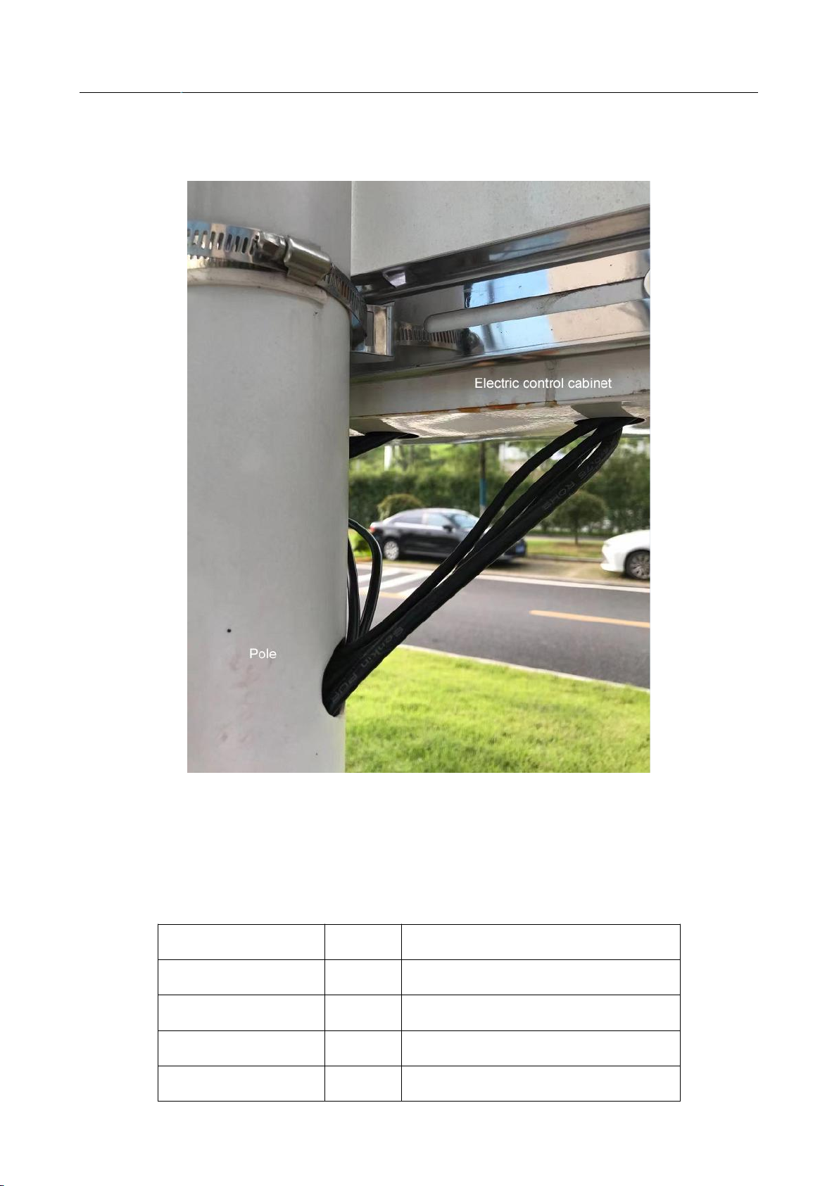
6. Install the electric control cabinet
6.1 Use the accessory hoop to install the electric control cabinet above the upper and lower pole
interfaces, as shown in the figure below:
FST100-QXZ-01 Environmental Monitoring System
13
6.2 The LED subsystem and sensor outlets are connected to the electric control cabinet through
the outlets at the bottom of the cabinet, as shown in the figure below:
6.3 The antenna should be as close as possible to the top of the electric control cabinet.
7. Subsystem electrical connection
7.1 LED display subsystem and electric control cabinet
LED cable
Docking
Electric control cabinet cable
AC FireWire
<->
Open fire line
AC neutral
<->
Open zero line
LED RS485 A
<->
DTU RS485 A
LED RS485 B
<->
DTU RS485 B
FST100-QXZ-01 Environmental Monitoring System
14
7.2 Solar and electric control cabinet (solar version)
Solar cable
Docking
Electric control cabinet cable
12V DC power output
<->
12V DC power input
7.3 Sensor and DTU
Sensor cable
Docking
Electric control cabinet cable
Sensor RS485 A
<->
DTU RS485 A
Sensor RS485 B
<->
DTU RS485 B
Power supply V+
<->
Rail power supply 12V +
(Can be connected in parallel with
DTU input power)
Power supply V-
<->
Rail power supply 12V –
(Can be connected in parallel with
DTU input power)

FST100-QXZ-01 Environmental Monitoring System
15
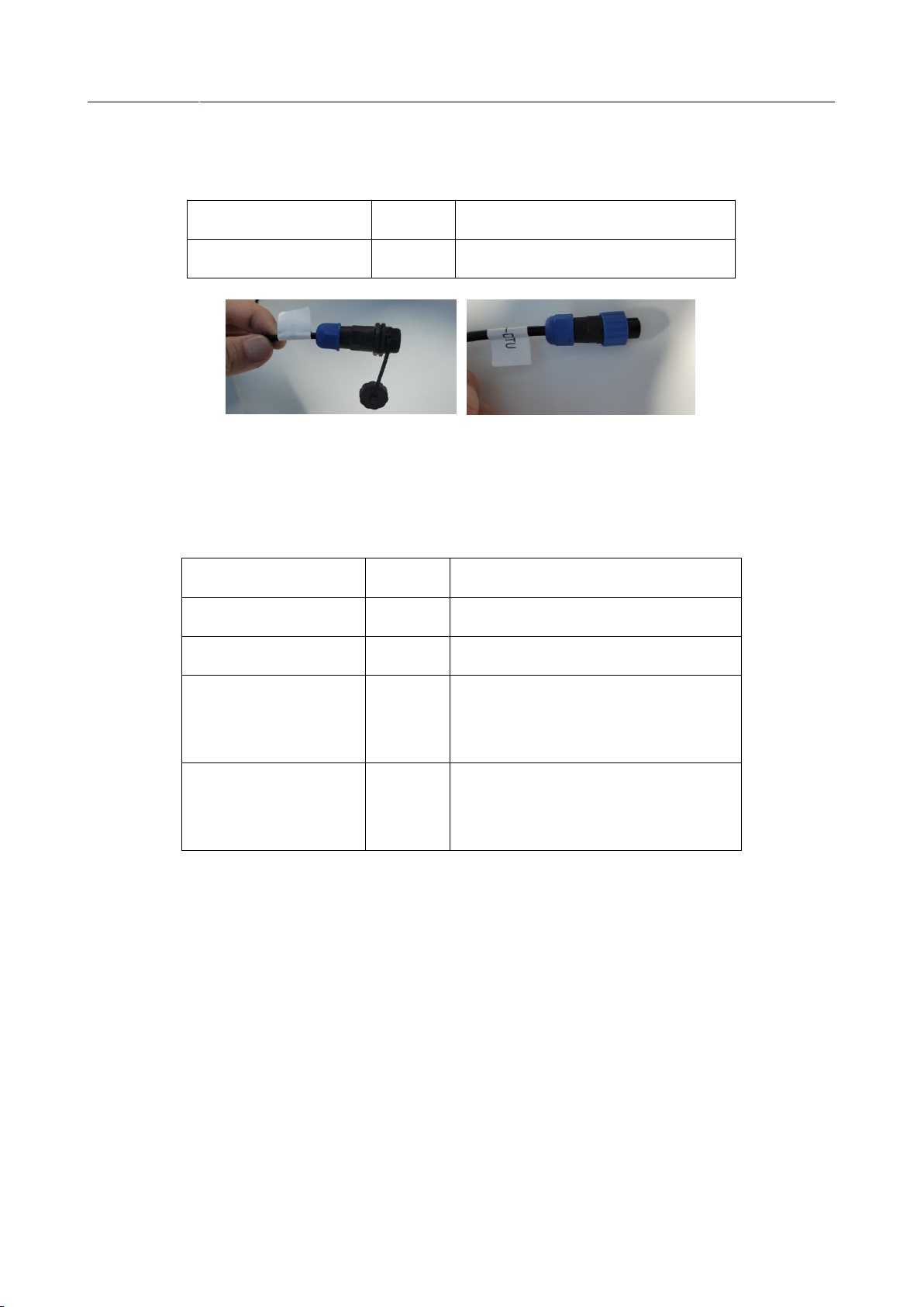
The sensor and the DTU connection cable are directly plug-in connection, as shown in the figure:

FST100-QXZ-01 Environmental Monitoring System
16

FST100-QXZ-01 Environmental Monitoring System
17
● Environmental Data Management Platform
Platform access address: http://47.112.149.41:8080/
Login account name: guest
Login account password:
If you need to create a separate account, please contact our business manager.
System functions:

FST100-QXZ-01 Environmental Monitoring System
18
● Matters needing attention
1. After opening the product packaging, please check whether the appearance of the product is
intact, verify whether the relevant content of the product manual is consistent with the product, and
properly keep the product manual for more than one year;
2. Strictly follow the wiring diagram of the product, and work under the allowable voltage of the
product, and do not use it over voltage;
3. Do not knock the product to avoid damage to the appearance and internal structure of the
ring;
4. The product has no customer repair parts, please contact our company in case of failure;
5. The company’s product fails under normal use, and the warranty period is one year (from the
date of delivery from the company to the date of return). Whether it is a failure under normal
conditions, the quality inspector of our company will check As the basis. For maintenance beyond
the time limit, the company will charge a basic fee, and all products of the company will be
maintained for life;
6. The instrument should be powered off to stop working during the period of being out of
service or in stock, which has prolonged the service life of the battery. The user should use the
same type of battery to replace the battery, and replace it under the condition of general good
condition and no gas leakage.
7. For the unexplained, please check our company website or call for inquiries.

Table of contents
Popular Weather Station manuals by other brands


WEATHER DIRECT
WEATHER DIRECT Weather Direct WD-3105 owner's manual

SE Controls
SE Controls Stand Alone Rain Sensor Technical information and operating instructions

Bresser
Bresser 4Cast PRO SF instruction manual

Denver
Denver TRC-1480 MK2 instruction manual

La Crosse Technology
La Crosse Technology 308-2408FR Faqs

Oregon Scientific
Oregon Scientific WMH90 user manual


