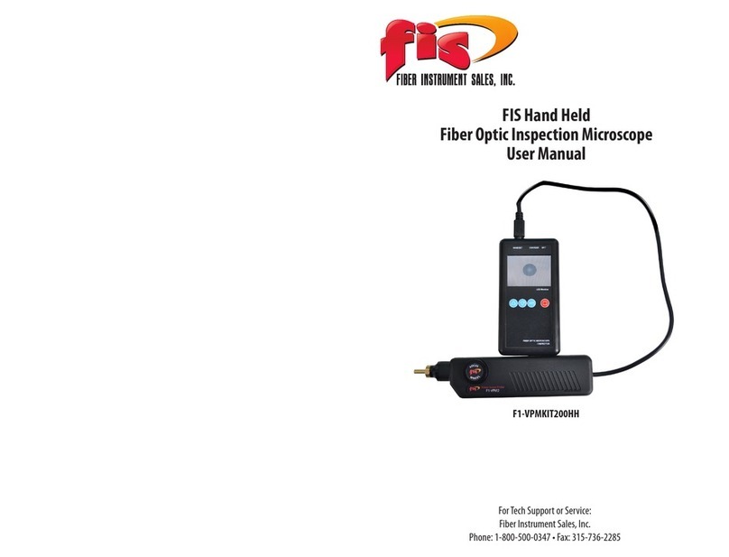
FIS MPO 12 User manual

MPO Test Set
User Manual


Introduction
The FIS 12 ber MPO test set, which is available in Multimode or Single
mode congurations, is a two-piece kit that contains a power meter
and light source designed to test and certify MPO-style cables quickly
and easily. This set will provide the user with link attenuation readings
(dB) over the 12 bers in less than 15 seconds as well as the ability to
verify A, B, C, and 40-Gig polarities. These units will work in virtually
any MPO application.
The power meter has the ability for the user to set dened
attenuation thresholds and will display a FAIL if any of the 12 bers
exceeds the threshold. If all bers are within the threshold, a PASS will
be displayed. This unit can also store up to 1,000 test results which can
then be transferred via the provided USB cable to the PC reporting
software, also included with the set.
The provided light source can emit optical signals at a constant
rate or with various modulated tones. It is programmed to run an
automated looped sequence through all 12 bers, a manual sequence,
to light up all 12 bers at once, or emit bers 1-4 and 9-12 for certain
“40 gig” applications. Both units have an auto-o feature which will
power down the unit after 10 minutes of being idle.

1
Fiber Instrument Sales, Inc. | 1.800.5000.FIS(347) | www.berinstrumentsales.com
Tour of Units
A) Male MPO test port: Insert a female MPO connector into the
power meter at all times.
B) Screen Heading: Whichever section of the interface you are
currently in will be displayed here.
C) Wave length tested: The current wavelength that the meter is
testing.
D) Battery indicator: Displays remaining battery life - when
charging, indicator will ash.
E) Unit display: By pressing left/right arrows, toggle between
dBm and dB units of measure.
F) Fiber count: Displays the ber number within the MPO cable.
G) Power value: Displays the power value for each corresponding
ber number within the MPO cable.
H) Pass/Fail threshold value: This can be set in the options menu
under “pass/fail thresholds”.
I) Auto-O: This feature is activated as the default setting every
time the unit turns on. To de-activate it, short press the “on/o”
button and it will disappear. To re-activate, simply short press
“on/o” button again.
J) F-Keys: These soft keys will perform multiple functions at any
given time in the unit. The command they perform will always
be displayed just above each key.
K) Arrow Keys: These keys typically will allow the user move
cursors and to make specic selections within the unit.
L) On/O: This button powers the unit on and o. To turn on or
o, long press this button for 3 seconds.
M) Zero/Test: This button has two functions. It will reference out
the power value of the reference cord and also test for polarity.
N) Mini-USB port: Insert the USB data cable to the unit here and
then connect to your PC to transfer data into the reporting
software.

2
Fiber Instrument Sales, Inc. | 1.800.5000.FIS(347) | www.berinstrumentsales.com
A
B
C
D
E
FG
H
I
J
K
L
M
N

3
Fiber Instrument Sales, Inc. | 1.800.5000.FIS(347) | www.berinstrumentsales.com
Power Meter Options
When turning the meter ON, you will be at the METER screen. To enter
the OPTIONS screen press F3. Once in MENU OPTIONS, use the up/
down arrows to move the cursor to your desired selection. Press F1 to
make the selection and F3 to go back to the METER screen:
1) Polarity Check: When coupled with the light source, this fea-
ture will allow the user to check their cable for a variety of polari-
ties. Use the arrow key to highlight your selection. Make sure to
have the source in AUTO MODE and connected to the power meter
when using this feature.
2) Pass/Fail Thresholds: Use this option to set your pass/fail
threshold. You can set a threshold down to the hundredths of a
dB (0.01). Use the left/right arrows to choose which placement
to control (dictated by the underscore {_}) and then use the up/
down arrows to the desired value. Press SET (F1) to lock in the
new threshold. Resetting the threshold (F2) will default the value
to 0.00dB at which no P/F threshold will be listed on the METER
screen (“P/F is O”).
3) Export Results: Select this option when the POWER METER is
connected to the PC. On the EXPORT screen you can use the up/
down arrows to select to export a single le, a range of les, or all
les. The up/down, left/right arrows will dictate which range of
les will be exported. Press F1 to export.
4) File Manager: This option allows the user to recall or erase les.
Follow the F-Key functions to carry out your commands.
5) Backlight: By highlighting this option, press F1 (select) to turn
the backlight on or o.

4
Fiber Instrument Sales, Inc. | 1.800.5000.FIS(347) | www.berinstrumentsales.com
Light Source
A) Male MPO test port: Insert a female MPO connector into the light
source at all times.
B) Wavelength: The wavelength contained in the source
C) Screen Heading: Whichever section of the interface you are cur-
rently in will be displayed here
D) Mode Selected: This will display the mode the user has selected for
the source in the options section.
E) Battery indicator: Displays remaining battery life, when charging,
indicator will ash
F) Fiber count (channel): Displays the ber number order within the
MPO cable
G) Source Icon: This icon indicates if the channel is illuminated.
H) Auto-O: For the source, this feature is de-activated as the default
setting every time the unit turns on. To activate it, short press (or tap)
the “on/o” button and “AUTO-OFF” will appear on top right of screen.
To de-activate, simply short press “on/o” button again and “AUTO-
OFF” will disappear.
I) F-Keys: These soft keys will perform multiple functions at any given
time in the unit. The command they perform will always be displayed
just above each key.
J) Arrow Keys: These keys typically will allow the user to move cursors
and to make specic selections within the unit.
K) Modulation Mode: When on the “Source” screen, pressing F-3 will
toggle between a constant source or a modulated frequency (tone).
L) On/O: This button powers the unit on and o. To turn on or o,
long press this button for 3 seconds.
M) Scan: Will toggle the source on and o.

5
Fiber Instrument Sales, Inc. | 1.800.5000.FIS(347) | www.berinstrumentsales.com
A
B
C
E
D
G
H
K
I
J
L
M
F

6
Fiber Instrument Sales, Inc. | 1.800.5000.FIS(347) | www.berinstrumentsales.com
Light Source Options/Operation
**PLEASE NOTE**: Before taking a reference, please let the source cycle
through in AUTO MODE for roughly ve minutes in order to stabilize the
power output of the source.
“In certain temperature conditions especially when using the Single
mode test kit, it may be necessary to re-reference roughly 10 minutes
after the initial reference. As is the case with any light source & power
meter setup, if at some point the test results seem skewed or unexpect-
ed, the primary tactic the user should take is re-referencing the source
to the meter. Make sure to always practice proper cleaning procedures
on all connectors and equipment during this process.”
When the unit is turned on you will be on the SOURCE screen. Once FIS
splash screen disappears the source will be running in AUTO MODE, which
is the default operation. This mode will continuously cycle through the 12
channels until you press F1 again. You will notice a lightly shaded round icon
moving through the channels when the source is active. When the icon goes
dark, the source is o. To change the mode at which the source operates,
select F2 to go into the OPTIONS screen. Only plug female MPO/MTP con-
nectors into the light source at all times.
Options: Here you can use the up/down arrow keys to highlight the dierent
modes of operation:
A) Auto Sequence: Continuous cycle through all 12 channels on the
SOURCE screen, turned on and o by pressing F1
B) Manual Sequence: Once selected, the user can control, on the
SOURCE screen, which channel gets illuminated by using the up/down
arrows to highlight a particular channel and the F1 (source) key to turn
the source on or o.
C) All On: Choosing this mode will allow the user to illuminate all chan-
nels at once when F1 is pressed on the SOURCE screen. It will run for a
maximum of 10 seconds before turning o. You can turn it o sooner
by pressing F1 again.
D) 40 Gig Sequence: This mode will run a continuous cycle through
channels 1 through 4 and 9 through 12 only on the SOURCE screen,
turned on and o by pressing F1.

7
Fiber Instrument Sales, Inc. | 1.800.5000.FIS(347) | www.berinstrumentsales.com
Power Meter Operation
Taking a reference and test: Two reference cord method
a. First turn on light source and press F1 to run source in Auto
Mode (default setting). Let it cycle through for about ve
minutes.
b. Clean the power meter port (male) as well as the female MPO
connector you are plugging in. Please do the same for the
Light Source port, which is also male.
c. Make sure you only insert female MPO connectors into the
power meter at all times.
d. Once the source has stabilized after ve minutes, connect your
Type A polarity reference cords (provided) to the power meter
and light source. Use the provided mating sleeve in the kit to
connect the two reference cords together between the meter
and source (male to female).
e. Now, while the light source is sequencing through, turn the
power meter on and conrm that the meter is reading power
(dBm) on each channel as the source sequences through.
f. When ready, press F1 on the METER screen (“Zero Ref”) to take
a power reference
g. Follow the on screen instructions…
h. Once the reference is complete, disconnect the reference cords
from each other in the middle and introduce the cable under
test in between them.
i. Once the ‘cable under test’ cable is introduced, highlight the
polarity type of the cable you will be testing with the arrow
cursor and press F1 when ready to test.
j. The Power Meter will now automatically go back to the METER
screen and run a relative loss test; the value of measurement
will be in dB.
k. Once the source has scanned all 12 bers, the Meter will have
the loss (dB) values displayed and only if a P/F threshold was
set, a PASS or FAIL will be displayed on the screen along with
the user dened threshold. If one ber exceeds the set thresh
old the entire test fails. A “P” represents an individual ber
passed and an “X” is an individual ber that failed.

8
Fiber Instrument Sales, Inc. | 1.800.5000.FIS(347) | www.berinstrumentsales.com
1) Once a test has completed you can press F1 (SAVE FILE) to enter the
le manager screen.
2) Now, you will notice current test results and the world FILE: ###.
The meter will default to the lowest le number that is available for
the test to be saved under.
3) If you wish to save the test results under a dierent le number, use
the left/right arrow keys to select the le number you wish to save it
under. Hold the left/right arrow key down to scroll through the le
numbers faster.
4) If the le number is already taken it will say “used”, if not, it will say
“free”. You can either overwrite a used le or save into a free spot.
5) The unit will always default to the next available free le slot for
which to save.
6) Once le desired le location is set, press F1 (Save) to conrm and
le will be saved.
7) Pressing F2 (Recall) will allow the user to view previously saved les,
with the option to erase or export the current recalled le. Again, the
left/right arrow keys will allow you to scroll through the les.
8) Once the present le is recalled, you can export, or erase the le by
following the on-screen commands assigned to the F-Keys on the unit.
9) You can also perform these functions in the le manager section of
the OPTIONS screen.
Saving a le

9
Fiber Instrument Sales, Inc. | 1.800.5000.FIS(347) | www.berinstrumentsales.com
A. Download the reporting software to your PC from the provided
USB memory stick. If the memory stick is lost or not available you
can download it from our website at www.berinstrumentsales.com/
downloads.
B. Open up the folder: “MPO_Test_Report 2.6”, then click on applica-
tion le “MPO_Test_Report”
C. The software will prompt you to connect the cable and to select a
folder for storage.
D. Using the provided USB serial cable, connect the meter to your PC.
E. You can select the provided default folder or create your own, then
select the folder.
F. Then the software will tell you to select a COM port to connect the
unit with the PC software.
G. Select available COM port. The software will conrm if meter is con-
nected to PC.
H. Within the Options menu on the power meter, select EXPORT RE-
SULTS.
I. You can now choose between exporting a single le, a range of les,
or all les. Toggle up/down, left/ght keys to navigate.
J. When ready, select Export (F1), the selected les will soon appear on
the left side of the computer screen within the reporting software.
K. Each le (i.e. 001) will contain the test results from the 12 channels.
Exporting les to the reporting software

10
Fiber Instrument Sales, Inc. | 1.800.5000.FIS(347) | www.berinstrumentsales.com
To generate a report in PDF:
• On the top menu, click“Reports”
• Then choose either “Generate” to convert highlighted le only,
or “Generate All” to generate all exported les
• To generate all les into a report, click “Generate All”. This will
convert all les currently exported into a PDF. Each le will
have its own page but all will be included in the same PDF le.

Notes:

Notes:

161 Clear Road
Oriskany, NY 13424
Ph: 315.736.2206 Toll Free: 1.800.5000.FIS(347) Fax: 315.736.2285
www.berinstrumentsales.com email: info@berinstrumentsales.com
Table of contents
Other FIS Test Equipment manuals
