FISCHBEIN D Series User manual

Form No.
116-1067
FISCHBEIN
SEWING
HEAD
SERIES
D
PARTS
ILLUSTRATIONS
MAINTENANCE
INSTRUCTIONS
ADJUSTMENTS
Copyright 1961
By
DAVE
FISCHBEIN
COMPANY
2700
30TH
AVENUE
SO.
MINNEAPOLIS.
MINN.
55406,
U.S.A.
U.S.A.
and
Foreign
Pats. Other Pats.
Pending
Printed
in U.S.A.
From the library of: Superior Sewing Machine & Supply LLC
S)ro—
®»—-
?
cn
^
CO
A
If
>
N
IH
From the library of: Superior Sewing Machine & Supply LLC

PLATE
B
80
1
74 73 72
71
63 64 65 66
From the library of: Superior Sewing Machine & Supply LLC

MAINTENANCE
Clean and oil machine daily. For best results, use genuine Fischbein Cleaning Solvent and Lubricating
Oil obtainable from the
Dave
Fischbein
Company
or any Authorized Representative.
Wash
out dirt as
follows:
Unthread
needle.
With
machine
running,
dip portion
shown,
Fig.
No.
1, in three or four inches
of solvent for about 10 seconds.
Then
in
addition
to the oil cups
on
the
machine,
oil all shafts, feed
dog carrier mechanism, and cutting knife parts. (Important: Do not use gasoline or similar as a cleaning
solvent.)
If
machine
skips stitches or fails to chain
off,
the cause
could
be any of the
following:
Excessive
wear,
requiring
rebuilding
or servicing;
improper
threading or tension (see special instructions on threading and
tension enclosed with this form); bent or incorrectly installed needle; damaged or misadjusted looper;
incorrect needle bar setting.
To
check these adjustments or replace these parts, carefully
follow
instructions
listed
below:
Do not disturb main bearing, part No. D605, or looper cam, part No. D310. They are timed and
set
at factory.
NEEDLE
INSTALLATION
Insert new needle into needle bar as far as it will go, with the long groove facing exactly outside of
machine.
The long
groove
will
enter into bar.
Lock
needle securelywith
wrench
provided
with
machine.
See Fig. No. 2.
LOOPER
INSTALLATION
Remove
needle,
throat plate,feed
dog,
and presser
foot.
(To
remove
presser
foot,
loosen
the
two
presser
foot
set
screws,
remove
needle
bar
guard,
part
No.
DlOl.
Using
a
screwdriver
as a
lever,
lift
up
the presser bar
clamp,
part
No.
D405,
which
will
allow
the presser foot
sufficient
clearance to
slide
off
the
bottom
of
presser
bar.
DO
NOT
loosen
or altersettingof the
presser
bar
clamp,
part
No.D405.
i
Loosen
looper
set
screw,
No.
SS832316
and
remove
old
looper.
Insert
new
looper,
making
sure that
it is
down
in
the
looper
holder,
part
No.D301-l,as
far as It
will
go.
Securely
tighten
looper
set
screw
against
flat
on
looper
shank.
Install
new
straight
needle.
NOTE;
The
point
of the
looper
must
pass
through
the center of the
needle
scarf
with
about
1/64"
clearance
between
looper
point
and
needle.
See
"A,"
Fig.
No.
3.
(The
scarf is the
hollowed
out
section
just
above
the
eye
of the
needle.
See
Fig.
No.
3.)
Unless
the
looper
holder
and/or
needle
bar
have
moved
or
have
slipped,
the
looper
will
time
up
automatically.
If
necessary,
adjust
clearance
between
looper
point
and
needle
by
loosening
the
looper
holder
clamp
screw
and
sliding
the
looper
holder
in
or
out
on
looper
shaft
as
required.
See next
paragraph
for
needle
bar setting.
LOOPER
TIMING
ADJUSTMENT
This adjustment does not have to be made when replacing the looper. but only after looper shaft, looper
cam, or cam follower has been replaced.
The looper stroke Is correct when there is approximately
1/32"
between looper point and edge of needle
when looper is at maximum back stroke. See "D," Figure No. 4. To adjust, first rotate machine in
sewing
direction
so that
looper
is at
maximum
back stroke
position,
then
loosen
clamp
screw
No.
SC54058in part
No.
D307
and
move
looper as necessary.
NEEDLE
BAR
ADJUSTMENT
Remove
needle
bar
guard,
part
No.
DlOl.
Torn
machine
pulley
in
normal
sewing
direction
until
looper
Is in
approximate
position
shown
in
Fig.
No.
5 as
needle
Is
on the
upstroke.
Slightly
loosen
clamping
screw on
needle
bar
clamp,
part
No.
D502.
Raise
or
lower
needle
bar and/or turn
machine
pulley
to
bring
looper
point
flush
with
or not
more
than 1/64"
back
from
edge of
needle,
see "B,"
Fig.
No.
5,
and
to
align
bottom
edge
of
looper
flush
with
top of
needle
eye,
see "C,"
Fig.
No.
5.
Do
not
change
looper
setting.
Securely
lock
needje
bar
clamp
and
replace
needle
bar
guard.
Recheck
for
proper
needle/looper clearance.
Fig.
No.
3.
STITCH
LENGTH
The length of stitch is
SVz
to the inch, when, at their highest point, the teeth of the feed dog protrude
3/32"
above the throat plate. If the stitches shorten up, check the following:
1. Teeth on feed dog may be worn down. Feed dog must then be replaced.
2. Feed dog
may
have slipped so that the teeth protrude less than 3/32".
Merely
raise the feed dog
by raising the adjusting screws No. HD64038 located on the feed carrier block. Note that there is a
set
of locking screws No. HD64038 on the under side of the feed carrier block.
D
Figure
No. 1
Figure No. 2
Figure
No.
3
Figure
No.
4
Figure
No.
5
From the library of: Superior Sewing Machine & Supply LLC
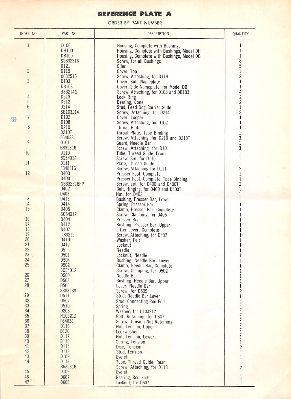
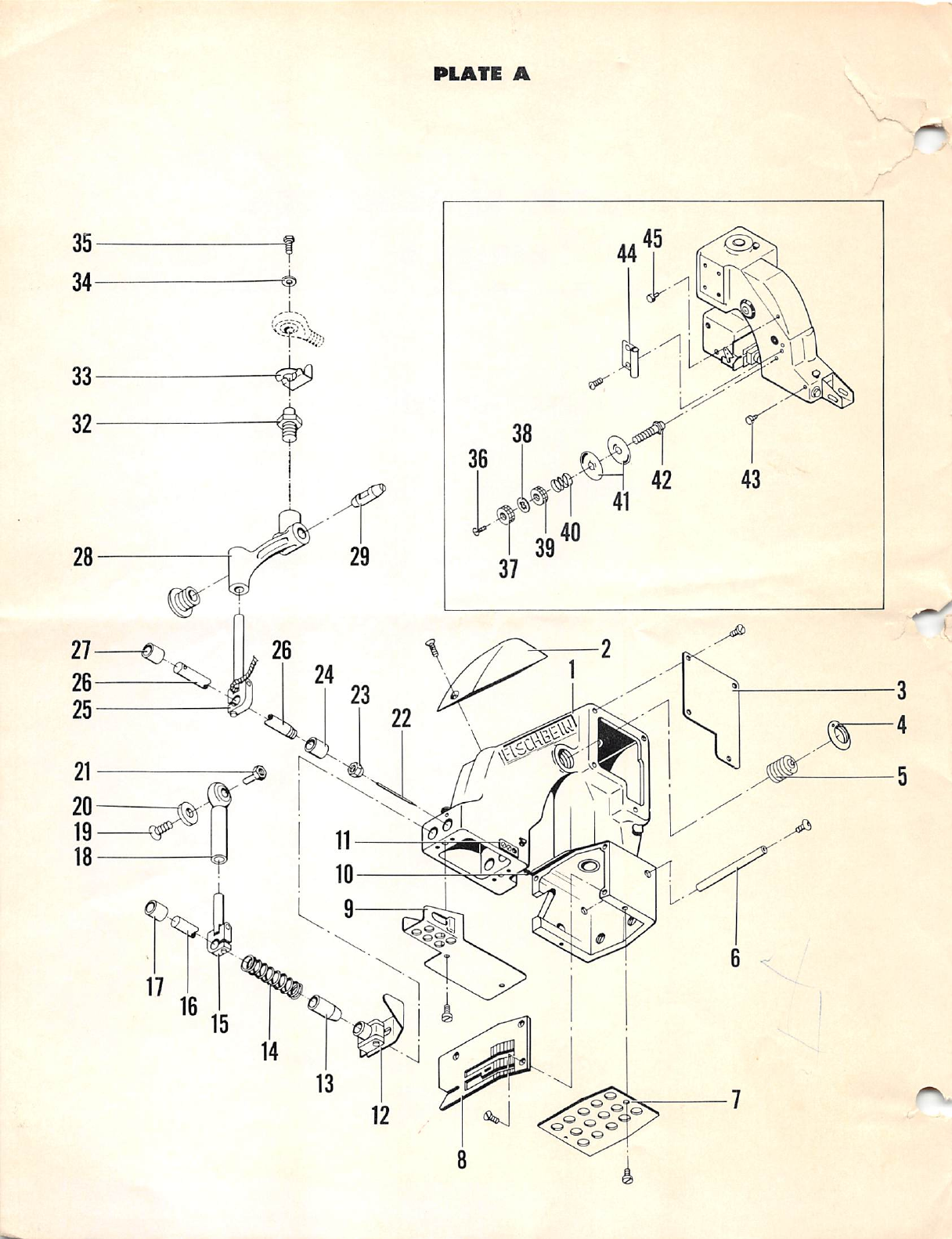
REFERENCE
PLATE
A
ORDER
BY
PART
NUMBER
INDEX NO. PART NO. DESCRIPTION QUANTITY
1DlOO
Housing,
Complete
with
Bushings
1
DHIOO
Housing,
Complete
with
Bushings,
Model
OH
1
DBIOO
Housing,
Complete
with
Bushings,
Model
OB
1
SS832316
Screw, for all Bushings 8
D121 Oiler 5
2
0119
Cover, Top 1
0632516
Screw,Attaching, for 0119 2
3D103
Cover,
Side
Nameplate
1
DB103
Cover,
Side
Nameplate,
for
Model
OB
1
B83214S Screw,Attaching, for 0103 and
DB103
4
4D513
Lock
Ring
2
5D512
Bearing,
Cone 2
6
0214
Stud, Feed
Oog
Carrier Slide 1
SB103214
Screw,
Attaching,
for 0214 2
0102
Cover,
Looper
1
rp
0108
Screw, Attaching, for 0102 1
8
0210
Throat
Plate
1
D210T Throat Plate, Tape
Binding
1
F64038
Screw,
Attaching,
for 0210 and
D210T
9
0101
Guard,
Needle Bar 1
B832316
Screw, Attaching, for 0101
10
0110
Tube,
Thread
Guide,
Front 1
SS54018 Screw, Set, for 0110 1
11
0111
Plate, Thread Guide 1
F348316
Screw, Attaching for 0111
12
0400
Presser Foot, Complete 1
D400T Presser
Foot,
Complete,
Tape
Binding
1
SS832318FP Screw, set, for 0400 and
D400T
0402
Bolt,
Hinging,
for 0400 and
D400T
1
0403
Nut, for 0402 1
13
0413
Bushing, Presser Bar,
Lower
1
14
0414
Spring, Presser Bar 1
15
0405
Clamp,
Presser
Bar,
Complete
1
16 SC54012 Screw,
Clamping,
for 0405 1
0404
Presser
Bar
1
17
0412
Bushing,
Presser
Bar,
Upper
1
18
0407
Lifter
Lever,
Complete
1
19
T83212
Screw,Attaching, for 0407 1
20
0410
Washer, Felt 1
21
0417
Locknut
1
22
05
Needle
1
23
0501
Locknut, Needle 1
24
0504
Bushing, Needle Bar,
Lower
1
25
0502
Clamp,
Needle
Bar,
Complete
1
26 SC54012 Screw,
Clamping,
for 0502 1
0500
Needle
Bar 1
27
0503
Bushing,
Needle
Bar,
Upper
1
28
0505
Lever, Needle Bar 1
SS83238
Screw, for 0505
29
0511
Stud.
Needle
Bar Lever 1
32
0507
Stud, Connecting
Rod
End
1
33
0510
Spring 1
34
0208
Washer, for H103212 1
35
H103212
Bolt,
Retaining, for 0607 1
36
F64038
Screw,
Tension
Nut
Retaining
1
37
0116
Nut,
Tension,
Upper
1
38
0120
Lockwasher
1
39
0117
Nut, Tension, Lower 1
40
0115
Soring,
Tension
1
41
0114
Disc,
Tension
42
0113
Stud, Tension 1
43
0109
Eyelet 1
44
0118
Tube,
Thread
Guide,
Rear 1
B632316 Screw, Attaching, for 0118
45
0109
Eyelet 1
46
0607
Bearing,
Rod
End
1
47"
D608 Locknut, for 0607 1
From the library of: Superior Sewing Machine & Supply LLC
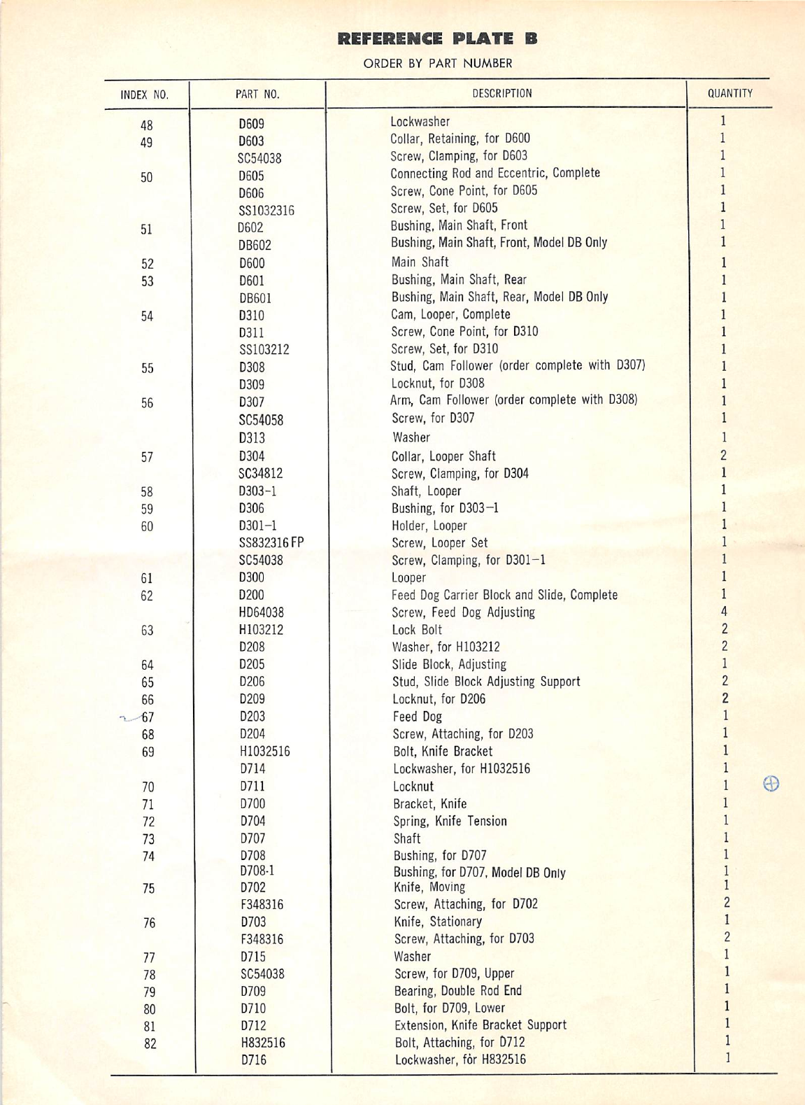
RiFERENCE
PLATE
B
ORDER
BY
PART
NUMBER
INDEX NO. PART NO. DESCRIPTION
QUANTITY
48 D609
Lockwasher
1
49
D603
Collar,
Retaining,
for 0600 1
SC54038
Screw,
Clamping,
for 0603 1
50
D605
Connecting
Rod
and Eccentric,
Complete
1
D6D6 Screw,
Cone
Point,
for 0605 1
SS1032316 Screw, Set, for 0605 1
51 D6D2
Bushing.
Main
Shaft, Front 1
DB602
Bushing,
Main
Shaft, Front,
Model
DB
Only
1
52 D600 Main
Shaft
1
53
0601
Bushing,
Main
Shaft,
Rear
1
DB601
Bushing,
Main
Shaft,
Rear,
Model
DB
Only
1
54 D310
Cam,
Looper,
Complete 1
D311 Screw, Cone Point, for 0310 1
SS103212
Screw, Set, for 0310 1
55
0308
Stud,
Cam
Follower
(order
complete
with
0307)
1
0309
Lockout, for 0308 1
56
0307
Arm,
Cam
Follower
(order
complete
with
0308)
1
SC54058 Screw, for 0307 1
0313
Washer
1
57
0304
Collar,
Looper
Shaft
SC34812
Screw,
Clamping,
for
0304
1
58
0303-1
Shaft,
Looper
1
59 D306
Bushing,
for 0303-1 1
60
0301-1
Holder, Looper 1
SS832316FP
Screw,
Looper
Set 1
SC54038
Screw,
Clamping,
for 0301-1 1
61
0300
Looper
1
62
0200
Feed
Oog
Carrier
Block
and
Slide,
Complete
1
H064038
Screw, Feed
Oog
Adjusting
4
63
H103212
Lock
Bolt
2
0208
Washer, for
H103212
2
64
0205
Slide
Block,
Adjusting 1
65 D206 Stud, Slide
Block
Adjusting Support 2
66
0209
Lockout,
for 0206 2
^.'-67
0203
Feed
Oog
1
68
0204
Screw, Attaching, for 0203 1
69
H1032516
Bolt,
Knife
Bracket 1
0714
Lockwasher,
for
H1032516
1 ©70
0711
Locknut
71
0700
Bracket,
Knife
1
72
0704
Spring,
Knife
Tension
1
73
0707
Shaft
1
74
0708
Bushing, for 0707 1
D708-1
Bushing,
for 0707,
Model
OB
Only
1
75
0702
Knife,
Moving
1
F348316
Screw, Attaching, for 0702
76
0703
Knife,
Stationary 1
F348316
Screw,
Attaching, for 0703
77
0715
Washer
1
78
SC54038
Screw, for 0709, Upper 1
79
0709
Bearing,
Double
Rod
End
1
80
0710
Bolt, for 0709,
Lower
1
81
0712
Extension,
Knife
Bracket Support 1
82
H832516
Bolt,
Attaching,
for
D712
1
0716
Lockwasher, for
H832516
1
From the library of: Superior Sewing Machine & Supply LLC

FISCHBEIN
PORTABLE
BAO
CLOSER-MODEL
D
HANDLE
AND
ELECTRIC
DRIVE
From the library of: Superior Sewing Machine & Supply LLC

PARTS
LrST
ORDER
BY
PART
NUMBER
INDEX
QUAN
NO.
PART
NO.
DESCRIPTION
TITY
1
D105-1
GUARD, BELT 1
D105-12
GUARD, BELT -
12
VOLT MODEL ONLY 1
R83258
SCREW,
ATTACHING
- FOR
DIOS
9
2
D909
BELT
1
D909-12
BELT
-
12
VOLT
MODEL
ONLY
1
3
D938
COUNTERWEIGHT
1
WS8
WASHER, LOCK 2
S883238
SCREW, SOCKET BUTTON 2
•909
PULLEY,
M9CHINE
1
SS1032516
SCREW, FOR
0909
2
5
•802
COVER,
SWITCH
1
063212
SCREW,
ATTACHING - FOR
0802
2
5
•807
INSULATION
1
D807DC
INSULATION
FOR
D806DC
1
7•
806
SWITCH
1
•806DC
SWITCH
-
DIRECT
CURRENT
ONLY
1
•819
SCREW, SWITCH TERMINAL
GROUND
3
8
•800
HANDLE
-
COMPLETE
WITH
COVER
1
D800DC
HANDLE -
COMPLETE
W/COVER
FOR
USE
W/D806DC
1
SC192039
SCREW,
ATTACHING
- FOR
D800
AND D800DC 2
9
•808
CORD
SET
1
•808-12
CORD
SET
-
12
VOLT
MODEL
ONLY
1
10
•809
CLAMP
FOR
D808
2
SS832316
SCREW
FOR
D809
1
11
•939
MOTOR
LEAD
- 3
WIRE
SJO
1
12
P3981
GRIP,
CORD 2
13
•815
THREAD
STAND
1
SF105238
SCREW, ATTACHING - FOR
D815
2
Ik
•805
WING
NUT
1
15
•809
BOLT,
THREAD
CLAMPING 1
16
•950
MOTOR -
115
VOLT
1
•951
MOTOR -
230
VOLT
1
•952
MOTOR
-
12
VOLT
DC 1
SF103238
SCREW, ATTACHING - FOR ALL
MOTORS
9
17
•902
PULLEY,
MOTOR 1
•902-12
PULLEY,
MOTOR -
12
VOLT MODEL ONLY 1
SS832316
SCREW - FOR
D902
2
SS836316
SCREW
- FOR
D902-12
2
•907-12
SPACER
-
FOR
12
VOLT
MODEL
ONLY
9
SF1G3258
SCREW, FOR
0907-12
9
ORDER
BY
PART
NUMBER
INDEX
QUAN-
NO.
PART
NO.
DESCRIPTION
TITY
18
•906
HINGED,
MOTOR MOUNT 1
•908
SCREW, SEMS LOCKING - FOR
D906
2
SF10323
8SCREW, ATTACHING FOR
0906
9
19
•927
PLATE, BALL BEARING CCLOSED) 1
•918
SCREW, BALL BEARING PLATE ATTACHING 9
20
•953
WASHER,
FELT RETAINING (CLOSED END) 1
21
•959
WASHER, SPACING AS REQ'D
22
•955
BALL
BEARING
2
•956
BALL
BEARING
-
FOR
12
VOLT
MODEL
ONLY
2
23
919-1
PLUG,
INSPECTION
HOLE 1
29
•917
SCREW, BRUSH - HOLDER CAP 2
25
•929-1
BRUSH
-
HOLDER
2
•929-12-1
BRUSH
-
HOLDER
-
FOR
12
VOLT
MODEL
ONLY
2
•930
SCREW, BRUSH - HOLDER SET 2
26
•957
END
BELL,
BRUSH END 1
•958
END BELL, BRUSH END - FOR 12 VOLT
MODEL
ONLY
1
•919
SCREW, ATTACHING - END BELL 9
27
•916
SPRING,
BRUSH 2
28
•915
BRUSH
2
•915-12
BRUSH
WITH
SPRING
-
FOR
12
VOLT
MODEL
ONLY
2
29
•959
9R.^'ATURE, COMPLETE -
115
VOLT 1
•960
ARMATURE, COMPLETE -
230
VOLT 1
•961
ARMATURE, COMPLETE - 12 VOLT 1
30
•925
RING
AND
FIELD
ASSEMBLY
COMPLETE
-
115
VOLT
1
•926
RING
AND
FIELD
ASSEMBLY
COMPLETE
-
230
VOLT
1
•925-12
RING
AND
FIELD
ASSEMBLY
COMPLETE
-
12
VOLT
1
31
D922
FIELD
-
115
VOLT
2
0923
FIELD
-
230
VOLT
2
D922-12
FIELD
-
12
VOLT
2
32
D962
WASHER,
BALL BEARING SPRING I
33
D963
END
BELL,
SHAFT
END 1
D919
SCREW, ATTACHING - END BELL 9
39
D969
WASHER,
FELT RETAINUJG (OPEN END) 1
35
•965
WASHER,
FELT
1
36
•966
•'LATE,
BALL
BEARING
(OPEN) 1
•918
SCREW, ATTACHING - FOR
D966
9
MOTOR
INSTRUCTIONS
This
motor
is intermittent
duty,
which
means that it
should
not run for
long
periods
of time
continuously.
It is
made
for start and stop operations
only,
such as required
by bag closing.
Brushes
should
be Inspected at
regular
intervals so that wear can be detected, and replaced before they are about
Vb"
in length.
To
remove
brushes, take out twoscrews
from
each side of
motor;
when
replacing brush, be sure It is replaced at the same
axial
position
as
removed.
If it Isn't, excessive sparking and loss of
power
will
result.
New
brushes are furnished with machine and can be purchased from us at any time.
No
motor
will
operate
properly
unless
the
bearings
are
kept
well
lubricated.
Ball
bearings
are
packed
with
grease
sufficient
for
a
period
of
from
one
to
two
years,
depend
ing
on
the
service
given
the
motor
and
temperature
of
the
room
in
which
It
operates.
To
refill,
remove
the
end
caos
covering
the
bearings
and
clean
out
the
old
grease
before
putting
in
the
new.
If
the
ball
bearings
are
removed
for
washing
in
gasoline,
the
built-in
grease
seal
should
be
facing
toward
the
motor
interior
when
replaced.
Use
only
well
known
make
of
SODIUM
BASE
BALL
BEARING
GREASE.
DAVE
FISCHBEIN
CO.. 2700 30th Ave. So., Minneapolis, Minnesota 55406,
U.S.A.
FORM
NO.
120-277
PRINTED
IN U.S.A.
From the library of: Superior Sewing Machine & Supply LLC


