Contents
1 General Information.......................................................................................................................1
1.1 Supporting Model ...............................................................................................................1
1.2 Method for Input.................................................................................................................1
1.3 Method for Display.............................................................................................................1
1.4 Layout of Panel...................................................................................................................1
1.5 Standardization....................................................................................................................1
1.6 Method for Operation..........................................................................................................1
2 Operational Instruction ..................................................................................................................2
2.1 Name & Description of Buttons on Control Panel..............................................................2
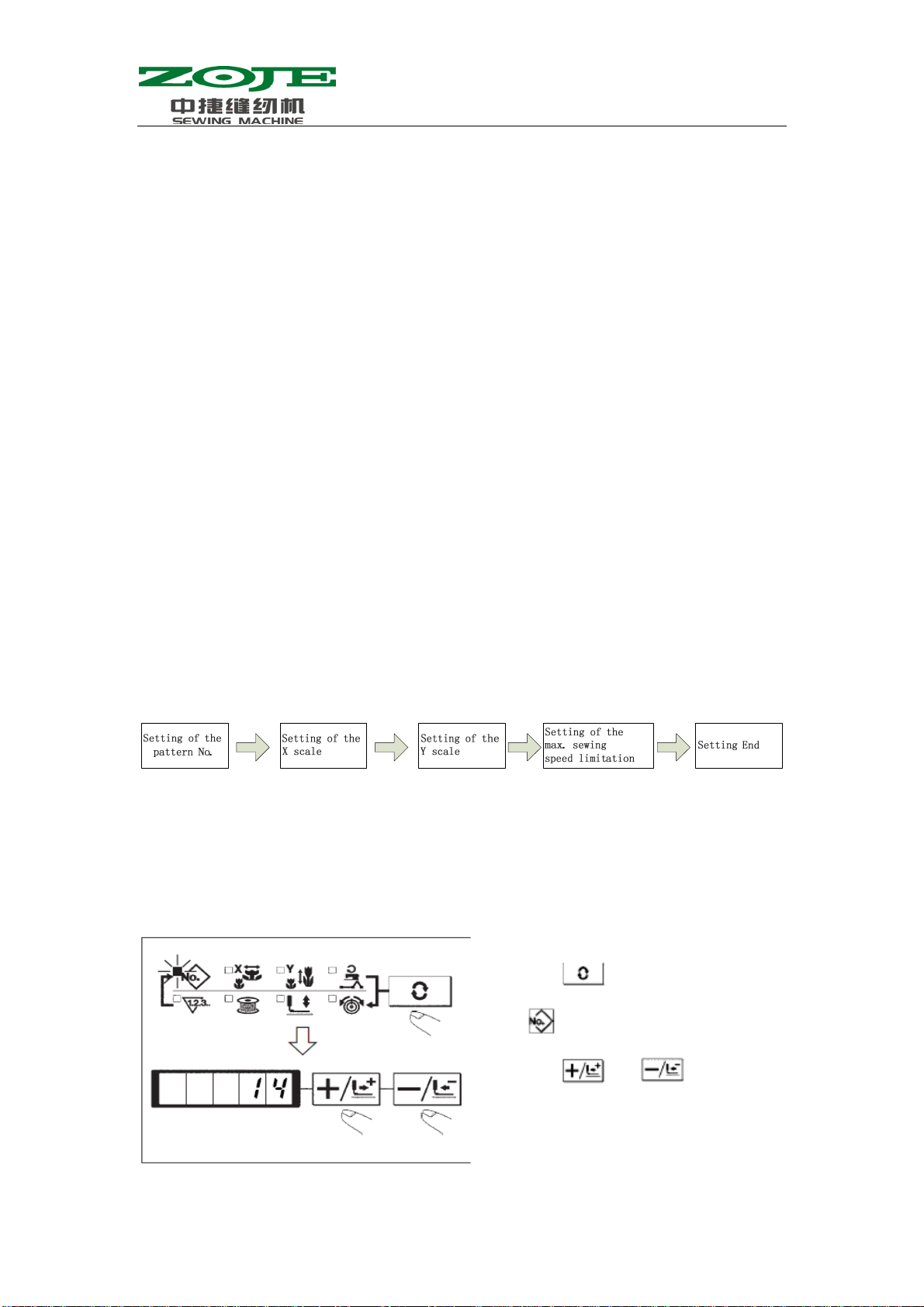
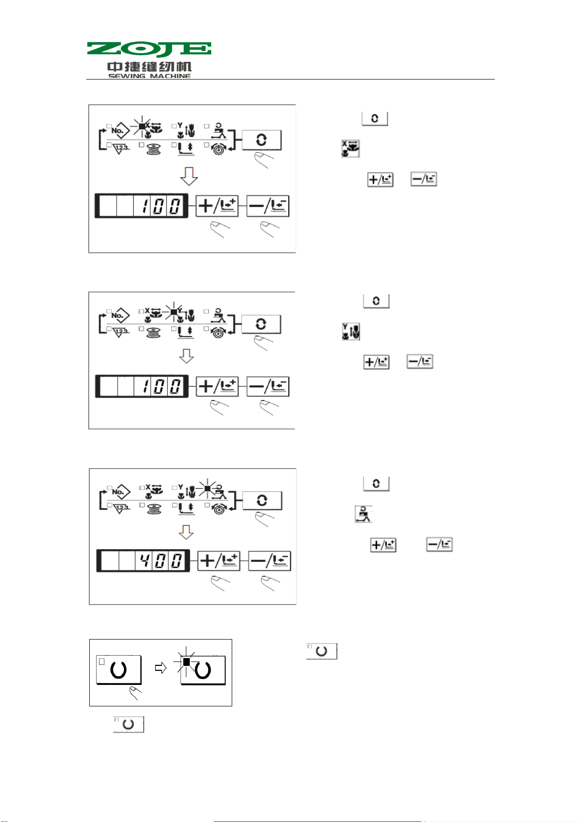
2.2 Basic Operation...................................................................................................................3
2.2.1 Settings of Item Data...............................................................................................3
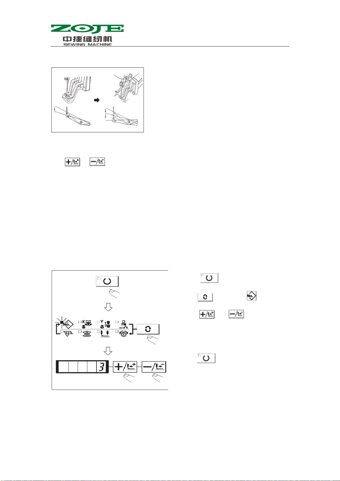
2.2.2 Confirmation of Pattern Shape................................................................................5
2.2.3 Sewing.....................................................................................................................6
2.2.4 Change to Other Patterns ........................................................................................6
2.2.5 Winding...................................................................................................................7
2.2.6 Independent Thread-trimming Device....................................................................7
2.2.7 Thread-catching Device ..........................................................................................7
2.2.8 Bottom Thread Counter...........................................................................................9
2.2.9 Pause.......................................................................................................................9
2.3 Set P Pattern & C Pattern..................................................................................................10
2.3.1 Use Pattern Key()for Sewing.............................10
2.3.2 Sewing with Combination Functions....................................................................12
2.4 Debugging Mode...............................................................................................................14
2.4.1 CP-1(Input Signal Test)...................................................................................17
2.4.2 CP-2(Check X/Y Motor/Origin Sensor)..........................................................18
2.4.4 CP-4(Test Main Motor Speed).........................................................................20
2.4.6 CP-6(Test Presser Origin Sensor)....................................................................24
2.4.7 CP-7(Test Thread-catching Motor/ Origin Sensor)..........................................24
2.5 Parameter Setting..............................................................................................................26
2.5.1 Specific Operations on Setting Parameters...........................................................26
2.5.2 Example for Setting Parameters............................................................................26
2.5.3 Table for Parameter Setting...................................................................................30
3 Setting of Service Parameter........................................................................................................33
3.1 Activation & Modification of Service Parameter..............................................................33
3.2 Table of Service Parameters..............................................................................................33
3.3 Recovery to Default Setting..............................................................................................35
3.3 List of Standard Figure......................................................................................................37
4 Function of Button Sewing..........................................................................................................41
4.1 Settings..............................................................................................................................41
4.2 List of Standard Pattern in Sewing Button........................................................................42
5 Appendix......................................................................................................................................44