– 2 –
#. INSTALLING IP-200 ON TABLE/STAN AND CONTROL BOX
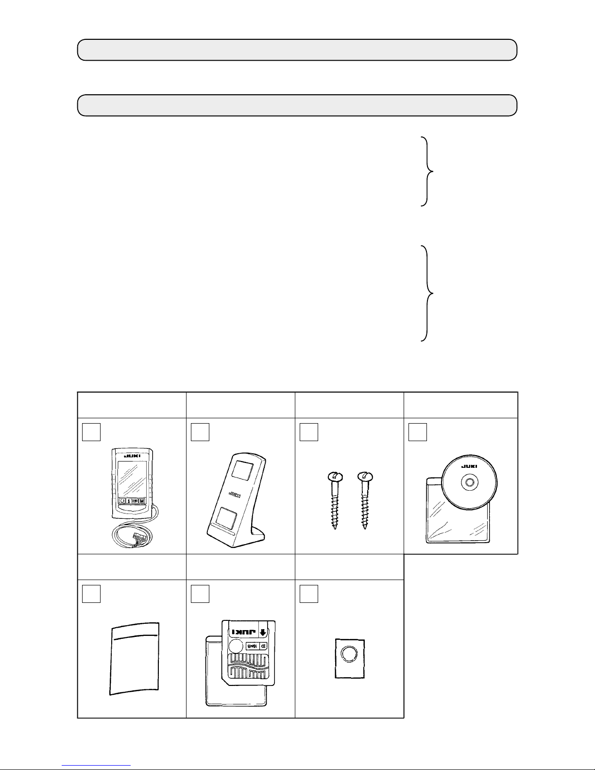
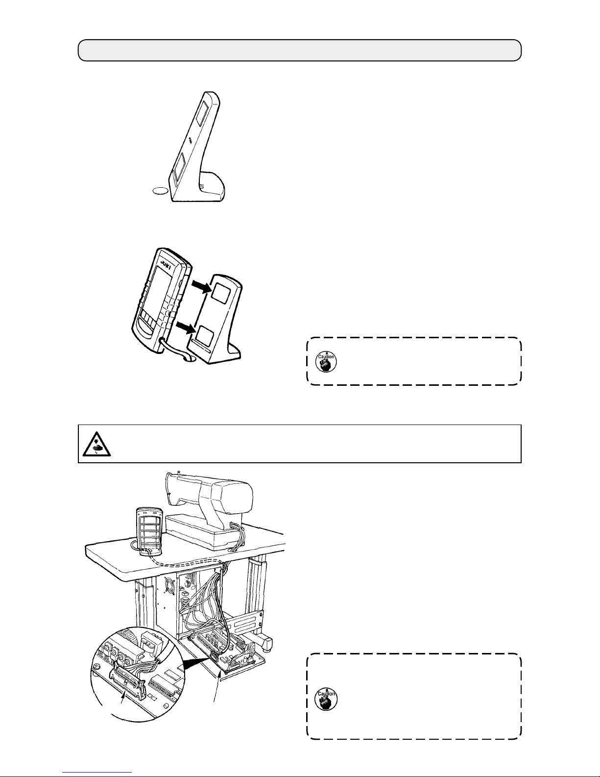
1. Installing procedure of the operation panel and the installing base
1) When installing the installing base, install it on the
table with the screws supplied as accessories.
At this time, consider the position of the hole for
wiring opened in the table to install the base.
In case of the table without the hole for wiring,
install the base at the position where there is no
trouble when the machine head is tilted or sewing
is performed.
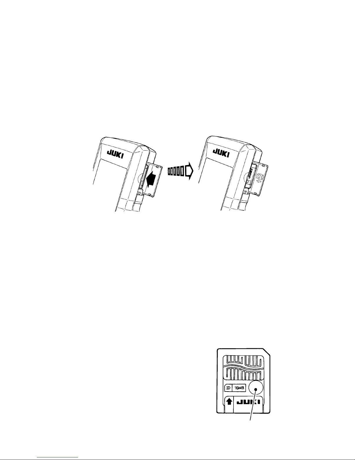
2) Operation panel can be fixed to the installing
base since the magnet on the rear of the
operation panel adheres to the installing base.
Besides, operation panel can be installed on the
metal part such as the side of the control box to
which the magnet adheres.
Do not put the articles which have little
resistance against the magnet near the
operation panel.
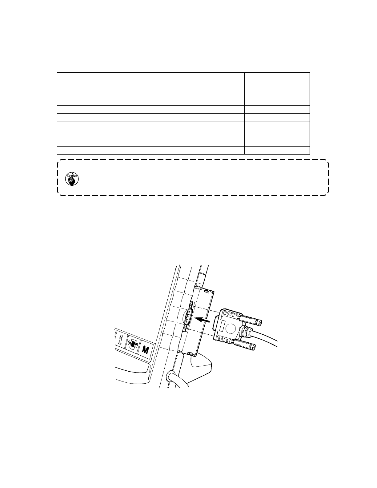
2. Connecting the cord and turning ON the power
1) Pass the cord of the operation panel through the
hole for wiring in the table and connect it with the
control box under the table. For the table without
the hole for wiring, wire the cord at the position
where there is no trouble when the machine head
is tilted or sewing is performed, and connect it
with the control box. For the connection of the
connector, connect it to CN34 of MAIN circuit
board in the control box or built in the machine
head. For the details, refer to the Instruction
Manual for the sewing machine main unit.
When the work above has been completed, turn
ON the power.
When connecting the cord, make
sure that the power of the main unit is
turned OFF. When connecting the cord
in the state that the power is turned
ON, trouble or breakage of the circuit
will be caused.
MAIN circuit board
CN34
WARNING :
Turn OFF the power before starting the connecting work so as to prevent accidents caused by abrupt
start of the sewing machine.