Pegasus MD Series User manual

MD
Device
9A2853E
Thank you for purchasing Pegasus' labor saving device.
Study this manual very carefully before beginning any
of the procedures and then use the device correctly and
safely.
Keep this manual in a convenient place for quick
reference when needed.
Elastic lace feeder
INSTRUCTIONS
Models: MD441
MD641
MD643

1.Introduction . . . . . . . . . . . . . . . . . . . . . . . . . . . . . . . . . . . . . . . . . . . . . . . . . . . . . . . . . . . . . . . . . . . . . . . . . . . . . . . . . . . . . . . . . . . . . . . . . . . . . . . . . . . . . . . 1
2.Indications of dangers, warnings & cautions . . . . . . . . . . . . . . . . . . . . . . . . . . . . . . . . . . . . . . . . . . . . . . . . . . . . . . . . . . 1-2
3.Safety precautions . . . . . . . . . . . . . . . . . . . . . . . . . . . . . . . . . . . . . . . . . . . . . . . . . . . . . . . . . . . . . . . . . . . . . . . . . . . . . . . . . . . . . . . . . . . . . . . . . . 2-3
4.Notes for each procedure . . . . . . . . . . . . . . . . . . . . . . . . . . . . . . . . . . . . . . . . . . . . . . . . . . . . . . . . . . . . . . . . . . . . . . . . . . . . . . . . . . . . . . . . 3-4
Applications and performance . . . . . . . . . . . . . . . . . . . . . . . . . . . . . . . . . . . . . . . . . . . . . . . . . . . . . . . . . . . . . . . . . . . . . . . . . . . . . . . . . . . . . 5
System construction . . . . . . . . . . . . . . . . . . . . . . . . . . . . . . . . . . . . . . . . . . . . . . . . . . . . . . . . . . . . . . . . . . . . . . . . . . . . . . . . . . . . . . . . . . . . . . . . . . . . . . . . . . 7
Installing each component . . . . . . . . . . . . . . . . . . . . . . . . . . . . . . . . . . . . . . . . . . . . . . . . . . . . . . . . . . . . . . . . . . . . . . . . . . . . . . . . . . . . . . . . . . . . . . 8-10
Description of MD power box . . . . . . . . . . . . . . . . . . . . . . . . . . . . . . . . . . . . . . . . . . . . . . . . . . . . . . . . . . . . . . . . . . . . . . . . . . . . . . . . . . . . . . . . . . . . . 11
Connecting cords . . . . . . . . . . . . . . . . . . . . . . . . . . . . . . . . . . . . . . . . . . . . . . . . . . . . . . . . . . . . . . . . . . . . . . . . . . . . . . . . . . . . . . . . . . . . . . . . . . . . . . . . . . . 12
Replacing the fuse for the power box . . . . . . . . . . . . . . . . . . . . . . . . . . . . . . . . . . . . . . . . . . . . . . . . . . . . . . . . . . . . . . . . . . . . . . . . . . . . . . . . . . 13
Connecting air lines and adjusting the filter regulator . . . . . . . . . . . . . . . . . . . . . . . . . . . . . . . . . . . . . . . . . . . . . . . . . . . . . . . . . . . . . . 14
Inserting elastic lace . . . . . . . . . . . . . . . . . . . . . . . . . . . . . . . . . . . . . . . . . . . . . . . . . . . . . . . . . . . . . . . . . . . . . . . . . . . . . . . . . . . . . . . . . . . . . . . . . . . . . . . . 15
Adjusting the guides according to the width of the elastic lace . . . . . . . . . . . . . . . . . . . . . . . . . . . . . . . . . . . . . . . . . . . . . . . . . . 16
Functions of the machine treadle/external switches . . . . . . . . . . . . . . . . . . . . . . . . . . . . . . . . . . . . . . . . . . . . . . . . . . . . . . . . . . . . . . . .17
Adjusting the sensitivity of sensor . . . . . . . . . . . . . . . . . . . . . . . . . . . . . . . . . . . . . . . . . . . . . . . . . . . . . . . . . . . . . . . . . . . . . . . . . . . . . . . . . . . . . . . 18
Description of MD console box . . . . . . . . . . . . . . . . . . . . . . . . . . . . . . . . . . . . . . . . . . . . . . . . . . . . . . . . . . . . . . . . . . . . . . . . . . . . . . . . . . . . . . . . . . . 19
Entering the sewing data . . . . . . . . . . . . . . . . . . . . . . . . . . . . . . . . . . . . . . . . . . . . . . . . . . . . . . . . . . . . . . . . . . . . . . . . . . . . . . . . . . . . . . . . . . . . . . 20-28
1. Before entry . . . . . . . . . . . . . . . . . . . . . . . . . . . . . . . . . . . . . . . . . . . . . . . . . . . . . . . . . . . . . . . . . . . . . . . . . . . . . . . . . . . . . . . . . . . . . . . . . . . . . . . . . . . . . . 20
2. Data entered at the factory . . . . . . . . . . . . . . . . . . . . . . . . . . . . . . . . . . . . . . . . . . . . . . . . . . . . . . . . . . . . . . . . . . . . . . . . . . . . . . . . . . . . . . . . . . . 21
3. Function selecting mode . . . . . . . . . . . . . . . . . . . . . . . . . . . . . . . . . . . . . . . . . . . . . . . . . . . . . . . . . . . . . . . . . . . . . . . . . . . . . . . . . . . . . . . . . 21-27
4. Changing PGM (items) . . . . . . . . . . . . . . . . . . . . . . . . . . . . . . . . . . . . . . . . . . . . . . . . . . . . . . . . . . . . . . . . . . . . . . . . . . . . . . . . . . . . . . . . . . . . . . . . 28
Sewing . . . . . . . . . . . . . . . . . . . . . . . . . . . . . . . . . . . . . . . . . . . . . . . . . . . . . . . . . . . . . . . . . . . . . . . . . . . . . . . . . . . . . . . . . . . . . . . . . . . . . . . . . . . . . . . . . . . . . 29-35
1. Programming patterns . . . . . . . . . . . . . . . . . . . . . . . . . . . . . . . . . . . . . . . . . . . . . . . . . . . . . . . . . . . . . . . . . . . . . . . . . . . . . . . . . . . . . . . . . . . . . . . . . 29
2. Programming steps . . . . . . . . . . . . . . . . . . . . . . . . . . . . . . . . . . . . . . . . . . . . . . . . . . . . . . . . . . . . . . . . . . . . . . . . . . . . . . . . . . . . . . . . . . . . . . . . . . . . 30
3. Finishing the program of step . . . . . . . . . . . . . . . . . . . . . . . . . . . . . . . . . . . . . . . . . . . . . . . . . . . . . . . . . . . . . . . . . . . . . . . . . . . . . . . . . . . . . . . 31
4. Programming the AT (automatic tape cutter) . . . . . . . . . . . . . . . . . . . . . . . . . . . . . . . . . . . . . . . . . . . . . . . . . . . . . . . . . . . . . . . . . . . . 32
5. To continue to sew pattern after pattern . . . . . . . . . . . . . . . . . . . . . . . . . . . . . . . . . . . . . . . . . . . . . . . . . . . . . . . . . . . . . . . . . . . . . . . . . . 33
6. To complete sewing when the current pattern is finished . . . . . . . . . . . . . . . . . . . . . . . . . . . . . . . . . . . . . . . . . . . . . . . . . . . . 33
7. Teaching . . . . . . . . . . . . . . . . . . . . . . . . . . . . . . . . . . . . . . . . . . . . . . . . . . . . . . . . . . . . . . . . . . . . . . . . . . . . . . . . . . . . . . . . . . . . . . . . . . . . . . . . . . . . . . . . . . 34
8. Sewing . . . . . . . . . . . . . . . . . . . . . . . . . . . . . . . . . . . . . . . . . . . . . . . . . . . . . . . . . . . . . . . . . . . . . . . . . . . . . . . . . . . . . . . . . . . . . . . . . . . . . . . . . . . . . . . . . . . . 35
Testing mode . . . . . . . . . . . . . . . . . . . . . . . . . . . . . . . . . . . . . . . . . . . . . . . . . . . . . . . . . . . . . . . . . . . . . . . . . . . . . . . . . . . . . . . . . . . . . . . . . . . . . . . . . . . . . 36-40
Error message . . . . . . . . . . . . . . . . . . . . . . . . . . . . . . . . . . . . . . . . . . . . . . . . . . . . . . . . . . . . . . . . . . . . . . . . . . . . . . . . . . . . . . . . . . . . . . . . . . . . . . . . . . . . . . . . 40

Indicates an immediate hazard to life or limb.
Indicates a potential hazard to life or limb.
Indicates a possible mistake that could result in injury or damage.
DANGER
WARNING
CAUTION
1.Introduction@@@@@@@@@@@@@@
●This manual describes the instructions for using this device safely.
●Study this manual very carefully and understand fully how to operate, check, adjust and maintain the labor
saving device before beginning any of the procedures.
●You always perform operations close to moving parts such as needles when using industrial sewing machines.
Therefore you have to keep in mind you could easily touch them. To prevent accidents, it is essential that you
use the safe products supplied by Pegasus correctly.
All the people who will use sewing machines must study this manual and the instruction manual for sewing
machines very carefully and then take necessary safety measures before beginning any of the procedures.
2.
Indications of dangers, warnings and cautions
@
To prevent accidents, indications (symbols and/or signs) which show the degree of danger are used on our
products and in this manual. Study the contents very carefully and follow the instructions.
Indication labels should be found easily.
Attach new labels when they are stained or removed.
Contact our sales office when new labels are needed.

Be sure to follow the instructions when you operate the machine and/or labor saving device.
If you use the machine and/or labor saving device incorrectly, you may get an electrical shock.
If you use the machine and/or labor saving device incorrectly, your hands and/or fingers may
be injured.
If you use the machine and/or labor saving device incorrectly, you may cause fire.
Never do this.
Unplug the machine or shut off the power when checking, adjusting and/or repairing the
machine and/or labor saving device, or when lightning may strike.
If you use the machine and/or labor saving device incorrectly, your fingers and/or hands
may be caught in them or it, causing trouble.
Indicates a danger of burn injury due to high temperature.
Be sure to ground the machine and labor saving device securely.
3.Safety precautions
①Applications, purpose
The labor saving device is designed to increase quality and
productivity according to you needs.
Therefore never use the device for the applications which may
defeat the above purpose.
②Circumstances
Some circumstances when you are using the labor saving device
may affect its life, function, performance, and safety.
For safety, do not use the labor saving device under the
circumstances below.
1.Do not use the device near objects which make noise such as a
high-frequency welder, etc.
2.Do not use or store the device in the air which has vapor from
chemicals, or do not expose the device to chemicals.
3.Do not leave the device outside, in high temperatures or the
direct sun.
4.Do not use the device in high humidity or ambient temperatures
which may affect them.
5.Do not use the device on the condition that the voltage fluctuation
range is more than ±10% of the rated voltage.
6.Do not use the device at the place where the supply voltage
specified for the control motor cannot be properly obtained.
7.Do not use the device at the place where the air supply specified
for the device cannot be properly obtained.
8.Do not expose the device to the water.
③Safety measures
(1)Safety precautions when you perform maintenance on
the labor saving device.
●When performing maintenance such as when checking, repairing,
cleaning the labor saving device, turn off the power, disconnect
the power plug from the outlet and press the machine treadle in
order to make sure the machine does not run.
If you have to perform maintenance on the machine and/or labor
saving device with the power on, always be careful because the
machine and/or device could start operating unexpectedly.
To prevent accidents caused by incorrect operation, you should
establish your own procedures for safe operation and follow
them.

●Only well-trained people should perform routine daily
maintenance and/or repair the machine and/or device.
●Do not modify the machine and device yourself.
※Consult you local Pegasus' sales office or representative for
modification.
(2)Before operating the device
●Before operating the device, check the machine head, machine
unit and device to make sure they do not have any damage
and/or defects.
Repair or replace any defective parts immediately.
●To prevent accidents, always make sure the safety covers and
safety guards are properly secured.
Never remove the safety covers and safety guards.
(3)Training
●To prevent accidents, operators and service/maintenance
personnel should have proper knowledge and skills for safe
operation.
To ensure so, managers must design and conduct training for
these people.
4.Notes for each procedure
CAUTION
CAUTION
①Unpacking
The machine and device are packed in boxes (and plastic bags) in
the factory before shipment. Unpack the boxes and bags properly
and sequentially by following the instructions shown on them.
②Installation, preparation
CAUTION
CAUTION
Connecting the air lines
1.Always turn off the power first and then connect the air lines to
the joints. Be sure to connect all the air lines before connecting
them to the air source.
2.When connecting the air lines to the joints, be sure to insert the
joints to the proper depth of the air lines and fasten securely.
3.Do not allow excessive force to be exerted on the air lines while
using the device.
4. Do not bend the air lines too much.
5.If necessary, protect the air lines by positioning them safely
and/or using the cover.
6. Do not use staples to secure the air lines. Otherwise it may
cause damage.
W
WARNING
ARNING
Connecting the cords
1. When connecting the power cord, be sure to turn off the
power and disconnect the power plug from the outlet.
2. Check the voltage designation to make sure the power
relay cord matches the local supply voltage. The use of wrong
cord may cause damage to parts and/or fire.
3.Do not allow excessive force to be exerted on the cords while
using the device.
4. Do not bend the cords too much.
5.Confirm that the cord is at least 25mm away from moving part of
the machine and/or the device when you connect the cord.
6.If necessary, protect the cords by positioning them safely and/or
using the cover.
7. Do not use staples to secure the cords. Otherwise it may
cause damage.
Ground
1.Connect each of the ground wires in the sewing machine system
to the ground terminal. Do not connect one devices' ground wire
to another devices'.
2. Connect the ground wires securely to the indicated ground
points on the machine head.
W
WARNING
ARNING
③Before operation
1.Check the cords, connector and air lines to make sure they do
not have any damage, disconnections or tangles and then turn on
the power.
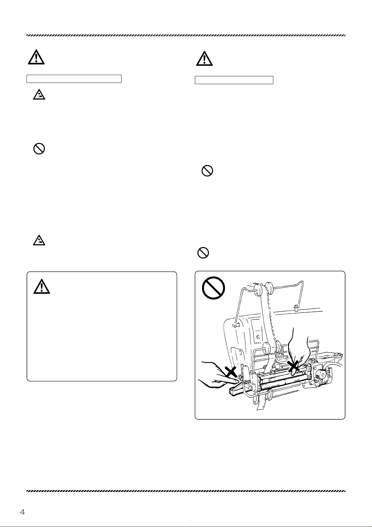
2. Do not bring your hands and/or any part of your body close
to the needle and pulley when turning on the power.
3.Well-trained people who studied this manual and the instruction
manual very carefully should use the machine with the labor
saving device.
4.Study the contents on "2. Indications of dangers, warnings and
cautions" very carefully and then provide users with safety
training as required.

W
WARNING
ARNING
④Precautions for work and operation
1. The area near the presser foot is very dangerous during
sewing. Do not bring your hands and/or any part of your body
close to the presser foot.
2.To prevent accidents, be careful that any foreign matter such as
water, other liquids or metals do not get into the device.
3.Wear clothes that cannot be caught in the machine.
4. Do not leave tools or other unnecessary objects near the
device.
5.To prevent accidents, always make sure the safety cover are
properly secured.
6.Drain and clean the filter regulator periodically, if the device is
pneumatic. Otherwise drainage will flow into the solenoid valve
and/or air cylinder, causing trouble.
7.Always turn off the power before leaving the machine table.
8.If any trouble occurs, stop using the machine and turn off the
power. Check, repair and/or perform other necessary procedures
immediately.
9. Pay close attention to the knife edges not to injure your
hands and/or fingers.
CAUTION
CAUTION
⑤Maintenance, check & repair
1.Well-trained people who studied this instructions very carefully
should maintain, check and repair the machine and device.
2.Perform routine daily maintenance and periodical maintenance by
following this instructions.
3.Use Pegasus' genuine parts when repairing and/or replacing
parts.
Pegasus disclaims all responsibility for accidents caused by
improper repair/adjustment and/or use of parts which are not
genuine.
4. Do not modify the device yourself.
Pegasus disclaims all responsibility for accidents caused by
modification.
5.After maintaining, checking, and/or repairing the machine and
device, always make sure that any trouble does not occur when
the power is turned on.
6.Before and after operation clean lint and any other foreign from
the device not to cause trouble.
7.Make sure to replace the safety covers when you need to remove
them for checking and/or maintenance.
To prevent accidents, never put your finger in knives and
roller. Be careful that sleeve cannot be caught in the roller.
Battery in the power box
The MD power box is equipped with a battery to keep the sewing
data as it is.
If the following happens, the battery may be dead or the power
box may be out of order.
Consult your local Pegasus sales office or representative.
(1) The sewing data which has been entered often changes.
(2) When the power is turned on, the sewing data is initialized.

Application and performance
The MD441, 641, 643 is an elastic lace feeder for attaching elastic lace to panties, lingerie and similar garments.
All you have to do is enter sewing data into the controller, then inserting and attaching elastic lace are just as easy as plain
seaming.
26 programs (items) from A to Z (kinds and/or sizes of garments) can be entered and stored. Up to five patterns per item
(sections to be sewn in a garment) can be entered and stored. Where to operate the tape cutter (at the start or end of sewing)
can be programmed in each pattern (1 to 5). In addition, up to seven steps (changing where to use fullness application and the
amount of fullness application during sewing) can be programmed and stored. When switching steps, you can select either
MANUAL (switching by the knee switch) or AUTO (switching by stitch counting) mode as you require.
Note : The tape cutter function is optional on MD441.
Feeding amounts and stitch counts can be
entered into up to seven steps.
The device can be used with only one step.
Item Operation
Program Pattern Auto Tape cutter Step
A
B
C
Z
STARTEND
STARTEND
STARTEND
STARTEND
STARTEND
1
2
■PROGRAM ( items : kinds and/or sizes of garments ) 26 items from A to Z can be entered.
For example, if elastic of the same width is used, program items as shown below.
Ex. ●Program 2 kinds of items (A, B) for leg openings
of different bottoms of panties.
3
4
5
6
7
1
2
3
4
5
6
7
1
2
3
4
5
1
2
3
4
5
26 items
5 patterns
per item
7 steps per pattern
A
B
●Program 2 kinds of items (C, D) for leg openings
of different bottoms of lingerie.
C
D

Start of sewing
AT start
Step 1
Step 2
Step 3
AT start
AT end
Step 3
Step 1
Step 2
■26 items from A to Z can be stored with up to five patterns (operations) per item.
For example, leg opening on the right, leg opening on the left.
Start of sewing
AT end
Pattern 1
Pattern 2
Ex.
Ex.
Program A Program B
■One to five patterns (operations) can be stored with up to seven steps.

System construction
*The knee switch and the filter regulator can be installed most conveniently.
Reel stand
Console box
Rotation detector
Power box
Knee switch
Machine treadle
MD device
Finger switch
(optional when you use the tape cutter)
Fabric detection sensor
Pneumatic tape cutter (optional on MD441)
Filter regulator (optinal on MD441)

1. Installing the console box
CAUTION
CAUTION
Always turn off the power, unplug the machine from
the outlet and then well qualified technicians should install
the console box.
1. Install console box 1on bracket 2.
2. Mount the console box bracket on the machine table.
2. Installing the power box
CAUTION
CAUTION
Always turn off the power, unplug the machine from
the outlet and then well qualified technicians should install
the power box.
Install controller on the underside of the machine table.
Installing each component
1
2

3. Installing the reel stand
CAUTION
CAUTION
Always turn off the power, unplug the machine from
the outlet and then only well-qualified technicians should
install the reel stand.
Install the reel stand on the machine table.
4. Installing the knee switch
CAUTION
CAUTION
Always turn off the power, unplug the machine from
the outlet and then only well-qualified technicians should
install the knee switch.
Install the knee switch conveniently on the underside of the
machine table.
Installing each component

5. Installing the finger switch (option)
Note: The finger switch is optional when you use the
tape cutter.
CAUTION
CAUTION
Always turn off the power, unplug the machine from
the outlet and then only well-qualified technicians should
install the finger switch.
Install the finger switch by referring to the illustration.
6. Installing the filter regulator
Note: Optional on MD441.
CAUTION
CAUTION
Always turn off the power, air compressor first and
then only well-qualified technicians should install the filter
regulator.
Connect other lines first before connecting to the air
source (air compressor).
Install the filter regulator on the underside of the machine
table.
Installing each component

Description of MD power box
1LED for power source
Indicates the power is on/off.
Lit when the power is on.
2Power connector (input)
To connect the power cord.
3Power switch
To turn ON or OFF the power of the MD power box.
4Fuse holder
3A fuse is included.
5Console box connector (input/output)
To connect cords from the console box.
6Sensor connector (input)
To connect the relay cord for the rotation detector and
fabric sensor.
7Input switch connector (input)
To connect the relay cord of the knee switch,finger switch
(optional for the tape cutter) or tape cutter (optional on
MD441).
8Out put connector (output)
To be connect to the relay cord of the tape cutter solenoid
valve (optional on MD441) or machine motor (used when
you want the machine to stop at the end of sewing).
9Stepping motor connector (output)
To connect the elastic lace feed stepping motor relay
cord.
10 Fabric detection sensor sensitivity adjusting dial
To adjust the sensitivity of the fabric detection sensor.
11 Fabric detection sensor sensitivity indicator lights
To check the sensitivity of the fabric detection sensor.
12 Fabric detection lights
To indicate the fabric sensor is detecting the fabric.
13 Fuse holder intended for users in Europe
3A fuse is included.
12
12
9
8
76
5
4 3 4 3
11
10
13
Specified for Europe

Connecting cords
W
WARNING
ARNING
Always turn off the power, unplug the machine from
the outlet and then only well-qualified technicians should
connect the cords.
Check the voltage designation 7to make sure the
power relay cord 1matches the local supply voltage. The
use of wrong cord may cause damage to parts and/or fire.
Each of cords and connectors is color- and shape-
coded. Connect the cords to the connectors correctly
as shown below.
Connect the earth wire correctly. Otherwise you may
get an electric shock when you touch the MD power box
and/or the machine.
Failure to connect properly may cause hazardous
faulty operations and damage to the machine.
After connecting cords, bundle these cords together using the cable tie provided.
Connect only when you use
the automatic stop function
(see page 13).
Note
To connect the power relay cord 1to the push-button switch 2, connect E
marked (or the green/yellow striped wire)to the GND terminal 3.
The other to cords must be connected to any 2 of the terminals 4, 5, and 6.
How to connect cords.
blue
white
orenge
yellow
Power
source
To machine motor
power connector
To the connector (optional)
on the machine motor control
blue
white
orenge
7
6 5
1
3
4 2

1
2
Replacing the fuse for the power box
Check to see if the terminal for the motor optional function such as
the standard or emergency stop is positioned correctly (see the
illustrations below). Then connect the cord to the motor connector
properly. The cord and connector are supplied with the motor.
*If you use different motors than the motors shown below, follow
the respective instruction manuals.
Black cord : 0V
White cord : Standard stop or emergency stop
●Mitsubishi UT motor cord ●Mitsubishi standard AC servo motor ●Panasonic standard servo motor cord
●Panasonic UT motor cord
White cord
White cord
White cord
Black cord
Black cord
Black cord
Cord side Cord side Cord side
Motor side Motor side Motor side
W
WARNING
ARNING
Be sure to turn off the power and disconnect the
power from the outlet, and then well-qualified technicians
should replace the fuse.
CAUTION
CAUTION
The fuse for the MD power box is 3A. Do not use any
other than 3A.
If the replaced fuse is blown out, the MD power box
may be malfunctioning. Stop using the MD power box and
contact your local Pegasus' sales office or representative.
Remove fuse holder cap 1with the screwdriver by turning
in the direction of the arrow, and replace the fuse 2with a
new one.
1

Connecting air lines and adjusting the filter regulator
5
8
2
1
3
4
7
6
9
10
11
12
Connecting air lines
CAUTION
CAUTION
Always turn off the power and air compressor first
and then only well-qualified technicians should connect the
air lines.
Connect other lines first before connecting to the air
source (air compressor).
Connect air line 1(from the air source) to joint 2and then
fasten it with hose clamp 3. Then connect filter regulator 4
to solenoid valve 5with air line 6.
Note
●Be sure to insert air line 6into joints 7and 8as far as it
will go. Make sure air line 6cannot be removed from
joints 7and 8by pulling air line 6.
●To remove air line 6, pull air line 6while pressing release
ring 9straight to the depth.
Adjusting air pressure
Pull up knob 10 on filter regulator until it clicks.
Then set the air pressure at 0.5 Mpa (5 kgf/cm2).
●Turning 10 in the direction increases the air pressure.
●Turning 10 in the direction decreases the air pressure.
Draining the filter regulator
Drain the filter regulator before collected drainage reaches
the level 11 by pressing button 12.
CAUTION
CAUTION
Be sure to drain periodically. Otherwise, drainage will
flow into the solenoid valve and/or air cylinder, causing
trouble.
Note that drainage and air spout out downward.

Inserting elastic lace
CAUTION
CAUTION
Be sure to turn off the power when inserting elastic
lace. Be careful that your hands are not caught in the roller
when performing the procedure.
11
1
36
1
2
3
4 4
5
6
7
89
10
1
2
7
1
13
12
9
8
210
(B)
(A)
1. Insert the elastic lace 1into roller 2as shown in the
illustration.
2. Adjust guides 4and 5so that elastic lace 1can go
through them smoothly. To make this adjustment, fit the
left edge of the elastic lace to fixed guide 3exactly first
and move guides 4and 5as needed in the direction of
the arrows.
3. Adjust guide 6so that elastic lace 1can go through
guides 3and 6smoothly. To make this adjustment, fit the
left edge of the elastic lace to fixed guide 3exactly first.
Then loosen screw 11 and move guide 6as needed in
the direction of the arrow.
4. Open roller 2by pressing lever 7and then insert elastic
lace 1.
5. Adjust guide 9so that elastic lace 1can go through guide
8and 9smoothly. To make this adjustment, fit the left
edge of the elastic lace to fixed guide 8exactly first.
Then loosen screw 12 and move guide 9as needed in
the direction of the arrow.
Note
Insert the elastic lace so that it will form a straight line as seen
from the front of the machine.
6. Adjust roller 2pressure so that the elastic lace can be
fed properly. To make this adjustment, turn nut 10
clockwise or counterclockwise as required.
• To decrease the pressure, turn in the direction of (A).
• To increase the pressure, turn in the direction of (B).
Note
The above procedures are for reference. Use guide 13 as
required according to the characteristics of the elastic lace.

Adjusting the guides according to the width of the elastic lace
CAUTION
CAUTION
Be sure to turn off the power when inserting elastic
lace. Be careful that your hands are not caught in the roller
when performing the procedure.
1.Right lace guide 5is set at the factory according to
20 mm elastic lace.
Adjust guides 1, 2, 3, 4and right lace guide 5according
to the width of the elastic lace .
(see Fig. A)
2.For 20 - 38 mm wide elastic lace:
Loosen screw 6and move right lace guide 5to the
extreme right end.
Then cut the left end of right lace guide 5so that 38 mm
elastic lace can go through easily.
(see Fig. B)
W
WARNING
ARNING
To prevent accidents when cutting lace guide (right) 5,
well-qualified technicians should perform the procedure,
being careful not to injure their fingers and/or hands.
3.For 38 - 92 mm (max.) wide elastic lace:
Replace right lace guide 5with lower lace guide
assembly 7.
Loosen screw 8and adjust guide 9according to the
width of the elastic lace.
(see Fig. C)
Fig.A
Fig.B
Fig.C
Max. 20 mm
Max. 20 mm
20 38 mm
38 mm Max. 92 mm
7
7
8
9
5
6
55
6
【Cut off】
【Cut here】
5
5
6
4
3
2
1

Functions of the machine treadle/external switches
Machine treadle
・・・・・Starts the machine.
CAUTION
CAUTION
Pressing the treadle starts the machine even while
the control panel is used to enter sewing data.
Knee switch
●In the MANUAL mode the machine goes to the next step
by pressing this switch.
●In the AUTO mode steps cannot be changed by pressing this
switch.
Finger switch (optional)
Pressing this switch operates the tape cutter.
Note
When you program the machine using the controller or if
ON is not selected on the AT function (see page 25) on
the function select mode, pressing the finger switch will
not operate the tape cutter.
Pressing the treadle with toes

The fabric detection sensor detects the end of the fabric at
the start of sewing so that the controller can count the num-
ber of stitches from the end of the fabric to a part of ruffling.
Therefore switching a ruffling operation is correctly done.
To adjust the sensitivity of the sensor
CAUTION
CAUTION
Well-qualified technicians should adjust the sensor
properly according to the fabric to be sewn. Otherwise the
tape cutter could get activated unexpectedly during sewing.
1.Turn on power switches 1and 2.
2.Ensure that no material is inserted when adjusting sensor
3.
3.Turn dial 4until the fourth from the left of indicator lights
6is turned on completely.
4.Turn dial 4clockwise slowly and stop turning dial 4until
the fifth light is turned on.
Check the indicator lights carefully if they are turned on/off
correctly with fabric or no fabric. (Confirm that the lamps
indicated by 6are all terned off when material is inserted.)
Adjusting the sensitivity of sensor
Note 1 : To sew special materials and/or extra light fabrics which the light from the sensor goes through, see below.
1. Turn dial 4until the third from the left of indicator lights
6is turned on completely.
2. Turn dial 4clockwise slowly and stop turning dial 4until
the fourth light is turned on.
Note 2 : Clean the reflector on the top surface of the needle plate. Otherwise malfunction may occur.
ON
1
2
4
5
6
MD power box
ON
2
3
Fabric
With fabric With no fabric
OnOff Off
Off On
On OnOff Off
4
4
4
4
On
Off Off
Off
Off On
This manual suits for next models
3
Table of contents
Other Pegasus Sewing Machine Accessories manuals
Popular Sewing Machine Accessories manuals by other brands

Schacht
Schacht LOOM BENCH Assembly instructions

Bernina
Bernina Medium Clamp Embroidery Hoop quick start guide

Grace Company
Grace Company surestitch Elite Assembly instructions

JUKI
JUKI DDL-7000A-7 Series instruction manual

ELNA
ELNA 200-314-028 quick start guide

DURKOPP ADLER
DURKOPP ADLER Kit 0367 595084 instructions