Fischer Connectors FO1 User manual

AssemblyInstructionforFiberOpticSeries
FO1

Assembly instructions rev. 6.1
2
This document is the property of Fischer Connectors.
This document must not be reproduced or distributed, in whole or in part, without prior written permission of Fischer Connectors.
Table of Contents
1 Introduction .............................................................................................................................................................. 3
2 Document history ..................................................................................................................................................... 3
3 Definitions and Acronyms ......................................................................................................................................... 3
4 FO1 Plugs & Rece tacles with Cable Clam Set ........................................................................................................ 4
5 FO1 Plugs & Rece tacles with Potting Set ................................................................................................................ 7
6 FO1 R01 & R03 Rece tacles with Wire Set ............................................................................................................. 11
7 FO1 R13 Rece tacle with Wire Set ......................................................................................................................... 13
8 Terminus assembly ................................................................................................................................................. 15
9 Polishing .................................................................................................................................................................. 17
10 A endix ............................................................................................................................................................. 25

Assembly instructions rev. 6.1
3
This document is the property of Fischer Connectors.
This document must not be reproduced or distributed, in whole or in part, without prior written permission of Fischer Connectors.
1Introduction
This document covers :
-The a lication of Fischer FiberO tic Series electrical contacts and o tical termini to electrical and fiber o tic
cables (singlemode and multimode fibers)
-The assembly of fiber o tic cable with a cladding size of 125 µm and having the cable structure described in
Fischer FiberO tic Series Cable S ecifications
-The assembly of Fischer FiberO tic Series electrical contacts and o tical termini and Rear Accessory sets
(Wire, Cable Clam and Potting sets) to Fischer FiberO tic Series single channel connectors (referred as FO1
in the resent document)
Please read these instructions thoroughly before starting assembly.
2Document history
Date Revision # Author Controller Modification description
15.03.2017 6.0 JGY SRH/CMI New Document
14.11.2019 6.1 JGY SKE Modification of stri ing dimensions for otting set
3Definitions and Acronyms
Text
Definition / Acronym
FO
Fischer FiberO tic
FO1
Fischer FiberO tic Series single channel
-
1 fiber
IEC
International Electrotechnical Commission

Assembly instructions rev. 6.1
4
This document is the property of Fischer Connectors.
This document must not be reproduced or distributed, in whole or in part, without prior written permission of Fischer Connectors.
4FO1 Plugs Receptacles with Cable Clamp Set
Assembly steps
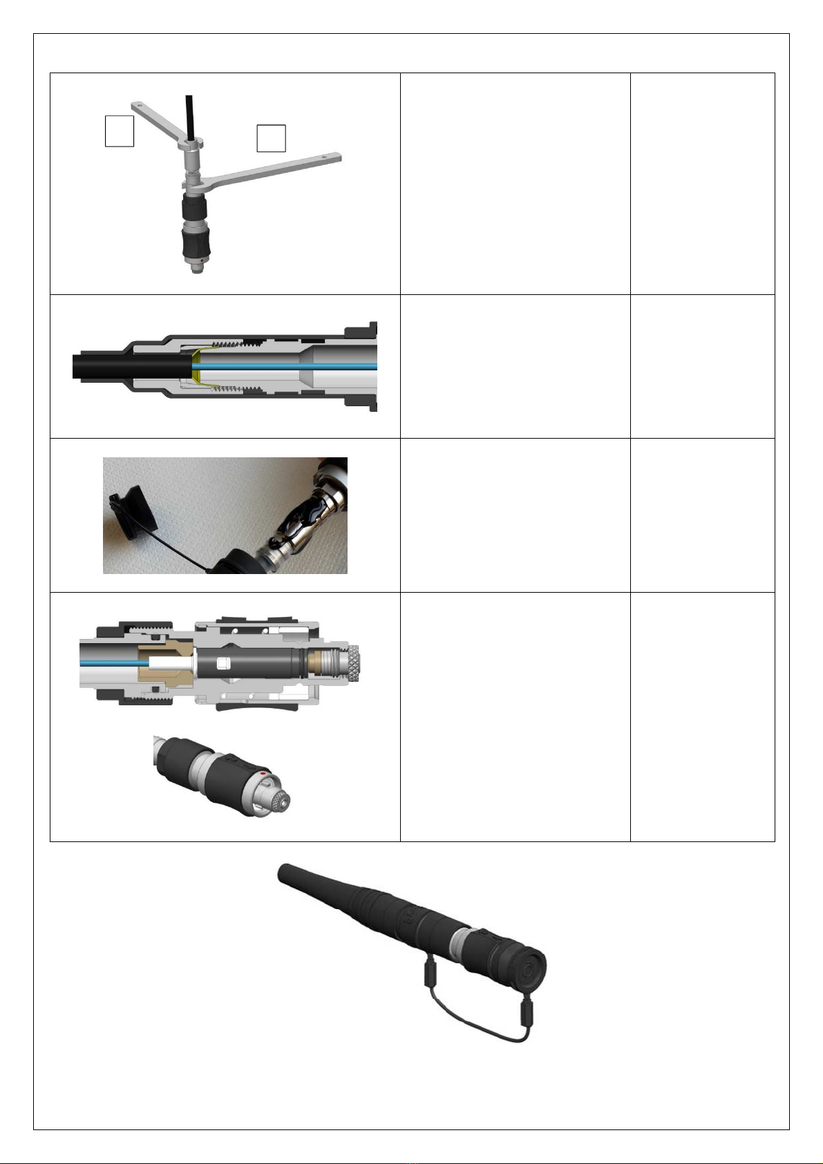
Com onents list :
A – Sleeve Holder
B – Connector Body
C – Terminus
D – Su ort Washer
E – O-ring Seal
F – Clam Set Body
G – Conical Ring
H – Clam Nut
I – Rear Nut
J – Shrink Tube
K – Bend Relief
Note : the ictures shown in this section re resent a P01 Plug.
The following assembly ste s are valid for P01 lug, as well as R01, R03 and R50 rece tacles, exce t the final ste
(sleeve holder assembly).
Picture
Process
Tools
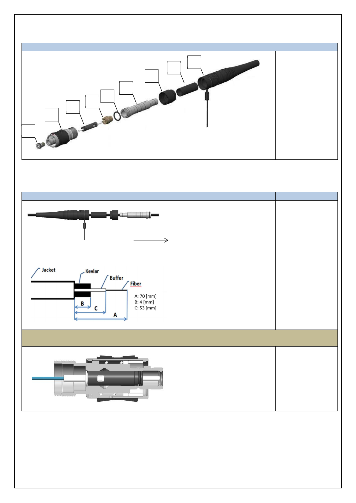
Slide over the cable :
-the Bend Relief “K”
-the Shrink Tube “J”
-the Rear Nut “I”
-the Clam Nut “H”
-the Conical Ring “G”
-the Clam Set Body “F”
-the O-Ring Seal “E”
S
tri the cable to the dimensions
as given on the icture.
R
uler, aramid
shears, jacket
stri er,
and stri tool
Terminus assembly : See section
8
Polishin : See section
9
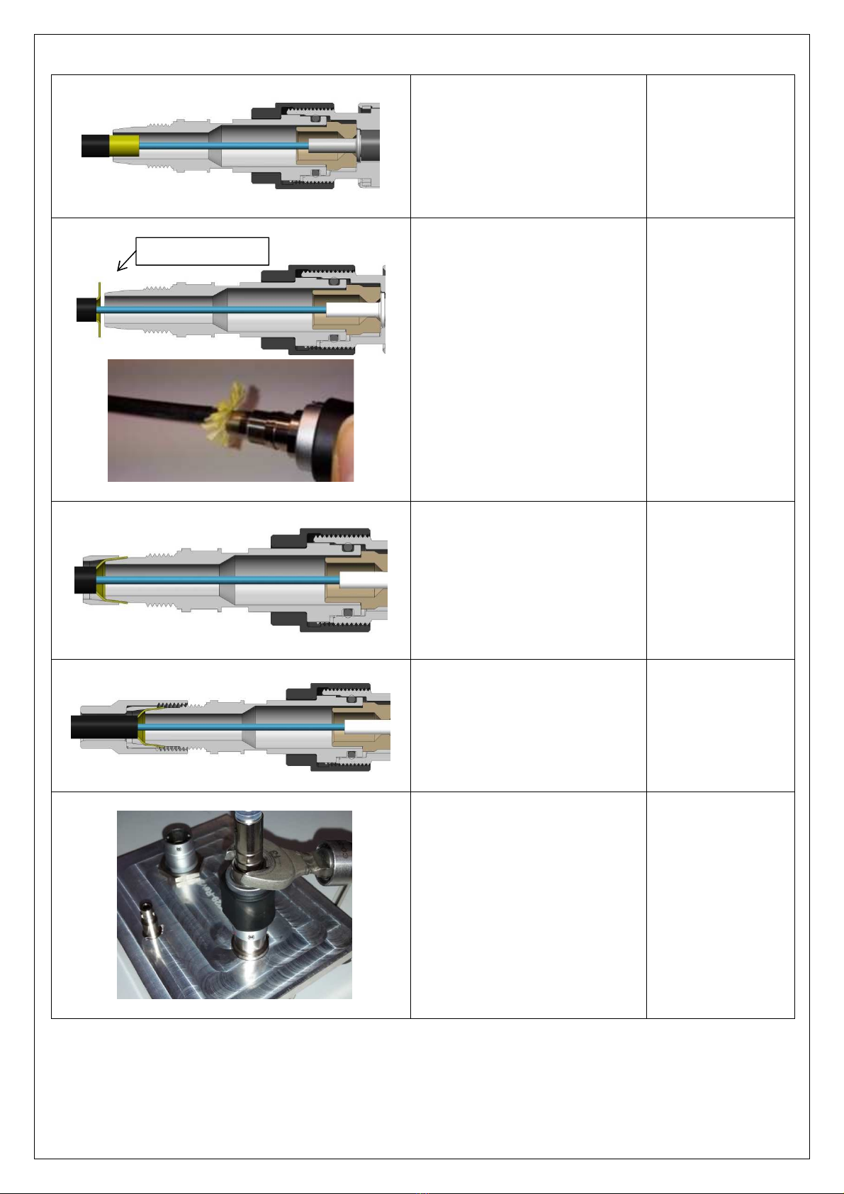
Insert the Terminus "C" into the
Connector Body "B".
Insert
the
Su ort Washer
"
D
"
and osition it around at the back
of the Terminus "C" as shown on
the icture.
A
B
C
D
E
F
G
H
I
J
K
Terminus side
Assembly instructions rev. 6.1
5
This document is the property of Fischer Connectors.
This document must not be reproduced or distributed, in whole or in part, without prior written permission of Fischer Connectors.
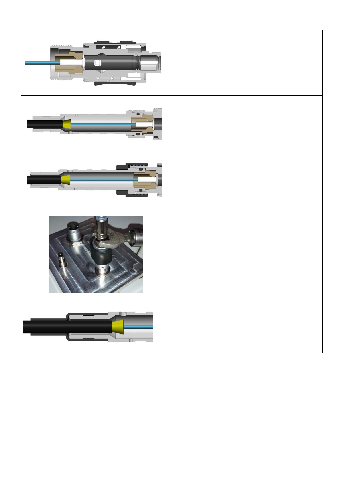
Position the O
-
Ring Seal “E” on the
Clam Set Body “F” then slide the
Clam Set Body “F” into the
Connector Body "B".
Screw by hand the
Rear
Nut “I” on
the Connector Body “B”, then
uniformly distribute the cable
strength members around the
back of the Clam Set Body “F”.
Position
the
Conical
Ring “
G
”
against the strength members.
Screw by hand the
Clam Nut
“
H
”
on the Clam Set Body “F”.
Screw the
Rear Nut
"
I
"
.
Recommended torque : 3.0 Nm
Strain relief
Assembly instructions rev. 6.1
6
This document is the property of Fischer Connectors.
This document must not be reproduced or distributed, in whole or in part, without prior written permission of Fischer Connectors.
Screw the Clam Nut ”H”
.
Recommended torque : 3.0 Nm
Note : hold the Clam Set Body
with a wrench while screwing the
Clam Nut “H”.
Clam Nut : wrench
size 5
Clam Set Body :
wrench size 6
Slide the
Shrink T
ube "
J
"
until the
end of the shrink tube bottoms
against the Back Nut “I” and heat
it.
Heat gun
Shrink tube
o erating
tem erature range :
-55°C to 110°C.
A ly e oxy on the Shrink Tube
"J" and slide the Bend Relief ”K”
until the end of the bend relief
bottoms against the Back Nut “I”.
E oxy: RT
-
355
Resintech
S
crew the
S
leeve
H
older "
A
" in the
Connector Body "B" until the
Sleeve Holder “A” is free to rotate.
Note : there is no sleeve holder for
R01, R03 and R50 rece tacles.
Thus, this final assembly ste is
valid only for P01 lug.
5
6
Assembly instructions rev. 6.1
7
This document is the property of Fischer Connectors.
This document must not be reproduced or distributed, in whole or in part, without prior written permission of Fischer Connectors.
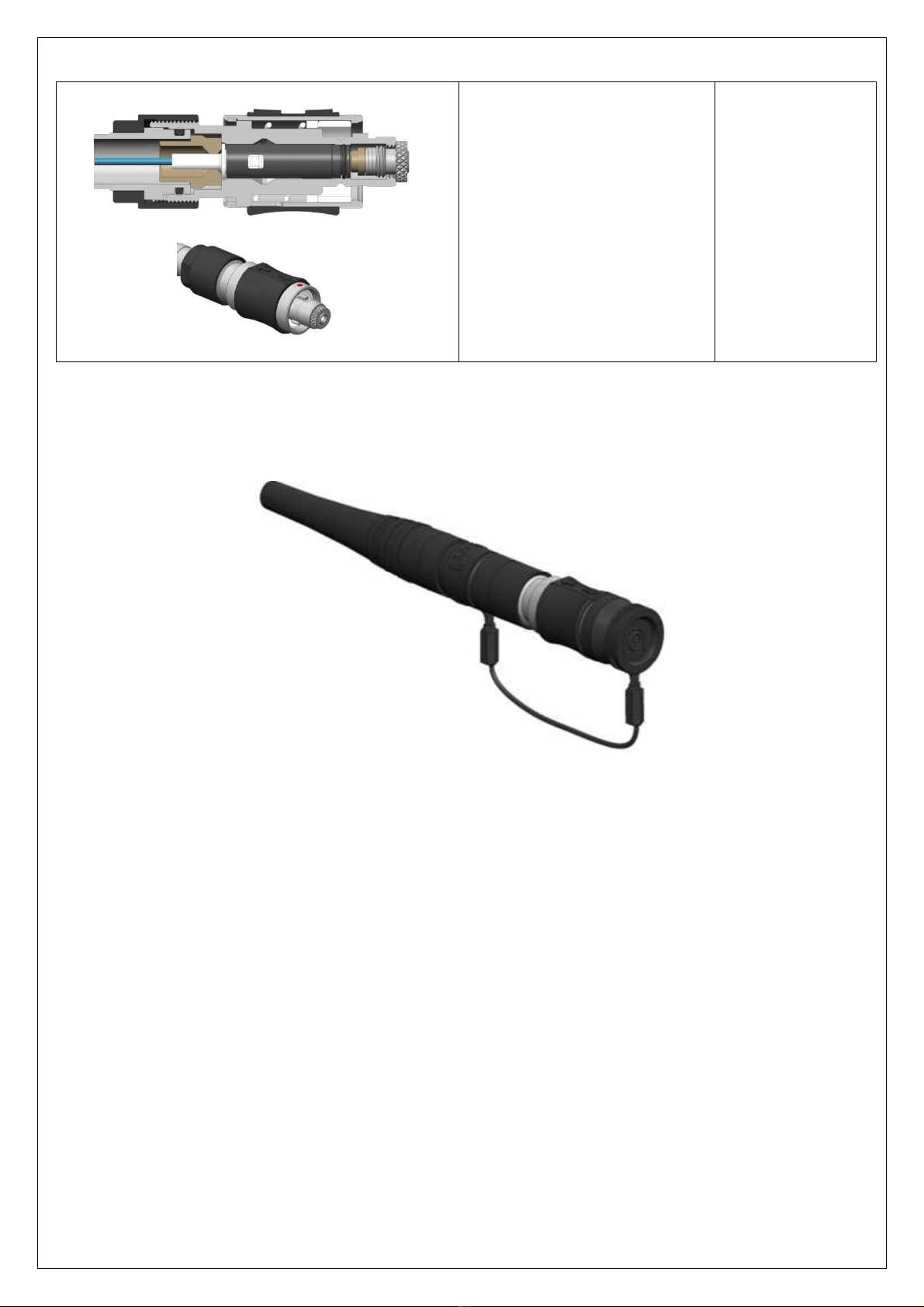
5FO1 Plugs Receptacles with Potting Set
Assembly steps
Com onents list :
A – Sleeve Holder
B – Connector Body
C – Terminus
D – Su ort Washer
E – O-ring Seal
F – Potting Set Body
G – Rear Nut
H – Shrink Tube
I – Bend Relief
Note :
the ictures shown in this section re resent a P01 Plug.
The following assembly ste s are valid for P01 lug, as well as R01, R03 and R50 rece tacles, exce t the final ste
(sleeve holder assembly).
Picture
Process
Tools
Slide over the cable :
-the Bend Relief “I”
-the Shrink Tube “H”
-the Rear Nut “G”
-the Potting Set Body “F”
-the O-Ring Seal “E”
S
tri the cable to the dimensions
as given on the icture.
R
uler, aramid
shears, jacket
stri er,
and stri tool
Terminus assembly : See section
8
Polishin : See section
9
Insert the Terminus "C" into the
Connector Body "B".
Terminus side
B
C
D
E
F
G
H
I
A
Assembly instructions rev. 6.1
8
This document is the property of Fischer Connectors.
This document must not be reproduced or distributed, in whole or in part, without prior written permission of Fischer Connectors.
Insert
the
Su ort Washer
"
D
"
and osition it around at the back
of the Terminus "C" as shown on
the icture.
Position the O
-
Ring Seal “E” on
the Potting Set Body “F” then
slide the Potting Set Body “F” into
the Connector Body "B".
Screw by hand the Rear Nut “G”
on the Connector Body “B”.
Screw the
Rear Nut
"
G
"
.
Recommended torque : 3.0 Nm
Rear Nut : wrench
size 9
Slide the Shrink T
ube "
H
"
until the
end of the shrink tube bottoms
against the Potting Set Body “F”
as shown on the left icture and
heat it.
Heat gun
Shrink tube
o erating
tem erature range :
-55°C to 110°C.
Assembly instructions rev. 6.1
9
This document is the property of Fischer Connectors.
This document must not be reproduced or distributed, in whole or in part, without prior written permission of Fischer Connectors.
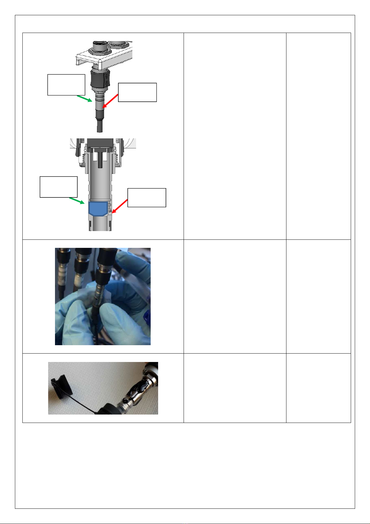
Slowly i
nject the e oxy inside the
Potting Set Body “F” using the
filling hole located at the bottom
of the Potting Set Body “F”.
Note : the second hole, smaller
and located above the filling hole,
is an overfilling hole. Sto
injecting e oxy when e oxy starts
to flow from this overfilling hole.
Resin E oxy RS 851
-
044 Black
Remove any excess e oxy from
the assembly (if any), a ly ta e
on both filling and overfilling
holes and lace the assembly
onto the curing oven block.
Curing time : 12
hours @ a rox.
23°C.
A ly e oxy on the Shrink Tube
"H" and slide the Bend Relief ”I”
until the end of the Bend Relief
”I” bottoms against the Back Nut
“G”.
E oxy: RT
-
355
Resintech
Overfilling
hole Filling Hole
(2mm)
Overfilling
hole Filling Hole
(2mm)
Assembly instructions rev. 6.1
10
This document is the property of Fischer Connectors.
This document must not be reproduced or distributed, in whole or in part, without prior written permission of Fischer Connectors.
S
crew the
S
leeve
H
older "
A
" in
the Connector Body "B" until the
Sleeve Holder “A” is free to
rotate.
Note : there is no sleeve holder
for R01, R03 and R50 rece tacles.
Thus, this final assembly ste is
valid only for P01 lug.
Assembly instructions rev. 6.1
11
This document is the property of Fischer Connectors.
This document must not be reproduced or distributed, in whole or in part, without prior written permission of Fischer Connectors.
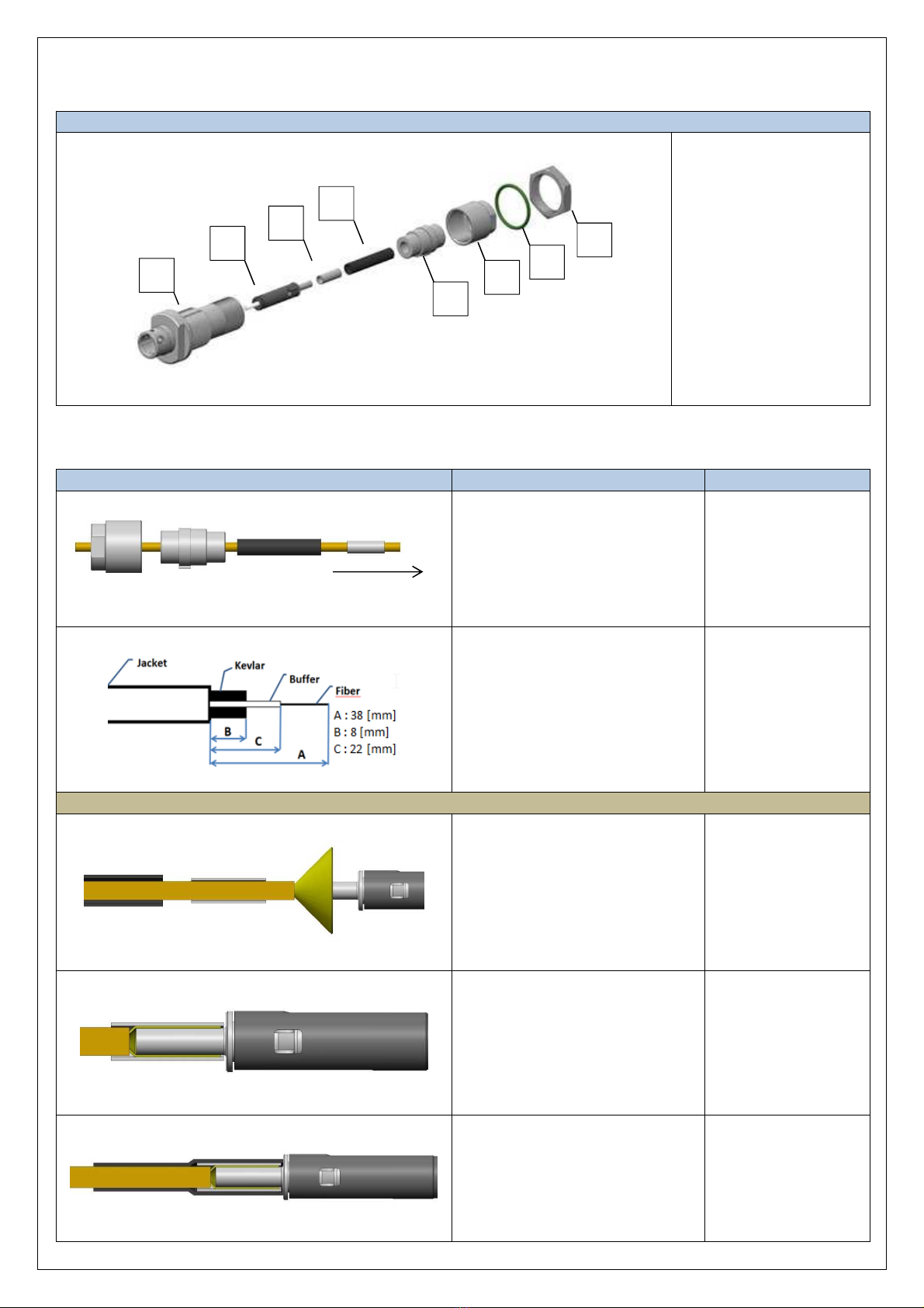
6FO1 R01 R03 Receptacles with Wire Set
Assembly steps
Com onents list :
A – Connector Body
B – Terminus
C – Crim Sleeve
D – Shrink Tube
E – Wire Set Body
F – Wire Set Nut
G – Connector Panel Seal
H – Connector Nut
Note : the ictures shown in this section re resent a R03 rece tacle.
The following assembly ste s are valid for R01 rece tacles as well.
Picture
Process
Tools
Slide over the cable :
-the Wire Set Nut “F”
-the Wire Set Body “E”
-the Shrink Tube “D”
-the Crim Sleeve “C”
S
tri the cable to the
dimensions
as given on the icture.
R
uler, aramid shears,
jacket stri er,
and stri tool
Terminus assembly : See section
8
Uniformly distribute the
cable
strength members around the
back of the Terminus “B”.
Slide the
Crim Sleeve “C”
over
the cable strength members until
the end of the crim sleeve
bottoms against the Terminus
“B”.
Find tools drawing in
a endixes.
Slide the Shrink Tube “D” over
the Crim ing Sleeve ”C” and heat
it.
Heat gun
Shrink tube
o erating
tem erature range :
-55°C to 110°C.
Terminus side
A
B
C
D
E
F
G
H

Assembly instructions rev. 6.1
12
This document is the property of Fischer Connectors.
This document must not be reproduced or distributed, in whole or in part, without prior written permission of Fischer Connectors.
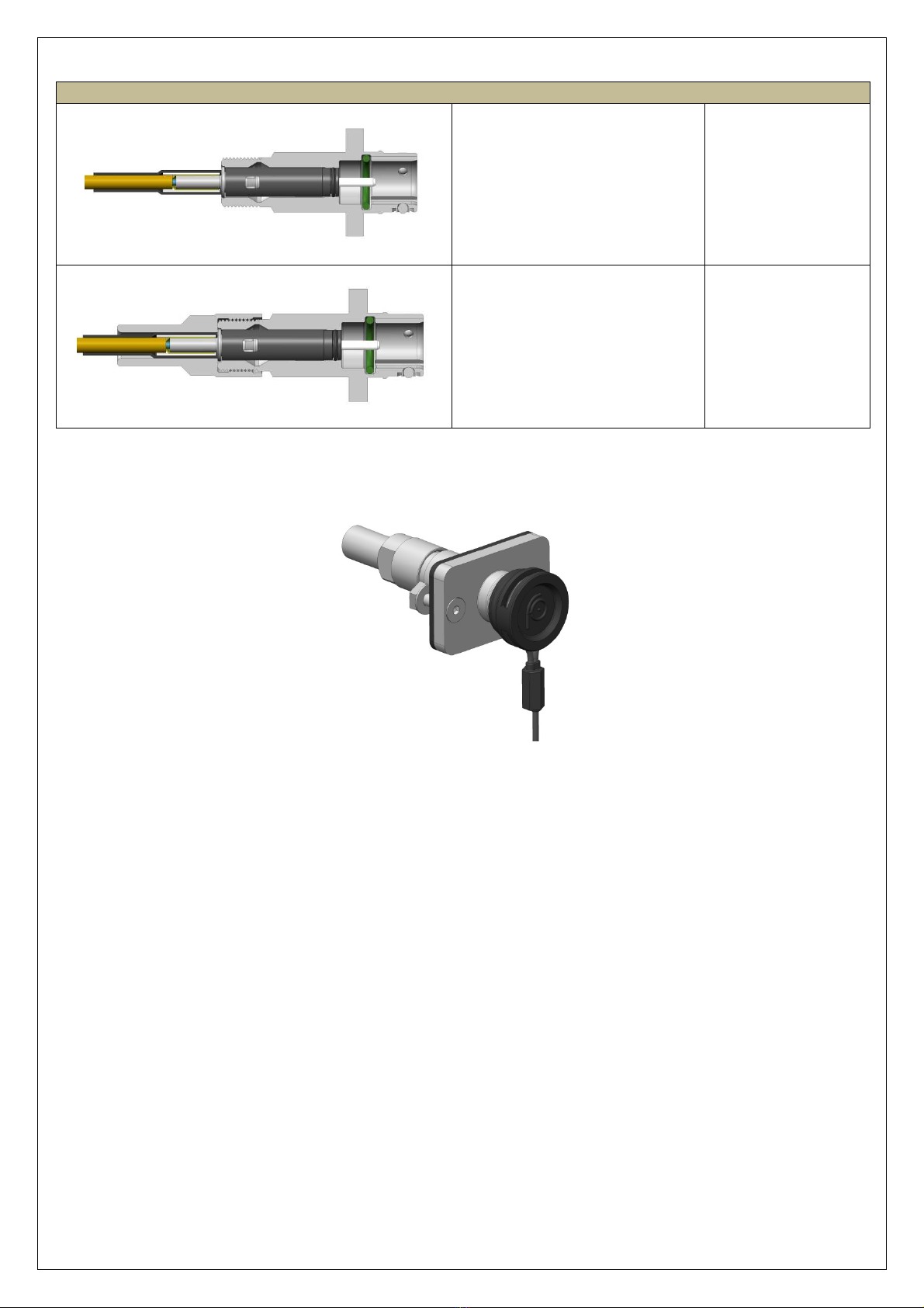
Polishin : See section
9
Insert the Terminus “B” into the
Connector Body “A”.
Insert the Wire Set Body “E” into
the Connector Body “A”.
Screw the Wire Set Nut “F” on
the Connector Body “A”.
Recommended torque : 3.0 Nm

Assembly instructions rev. 6.1
13
This document is the property of Fischer Connectors.
This document must not be reproduced or distributed, in whole or in part, without prior written permission of Fischer Connectors.
7FO1 R13 Receptacle with Wire Set
Assembly steps
Com onents list :
A – Screws
B – Connector Body
C – Terminus
D – Crim ing Sleeve
E – Shrink Tube
F – Wire Set Nut
G – Connector Panel
Seal, Washers & Nuts
Picture
Process
Tools
Slide over the cable :
-the Wire Set Nut “F”
-the Shrink Tube “E”
-the Crim Sleeve “D”
S
tri the cable to the dimensions
as given on the icture.
R
uler, aramid shears,
jacket stri er,
and stri tool
Terminus assembly : See section
8
Uniformly distribute the cable
strength members around the
back of the Terminus “B”.
Slide the
Crim Sleeve “
D
”
over
the cable strength members until
the end of the crim sleeve
bottoms against the Terminus
“C”.
Find tools drawing in
a endixes.
Slide the Shrink Tube “E” over the
Crim ing Sleeve ”D” and heat it.
Heat gun
Shrink tube
o erating
tem erature range :
-55°C to 110°C.
Terminus side
A
B
C
D
E
F
G
Assembly instructions rev. 6.1
14
This document is the property of Fischer Connectors.
This document must not be reproduced or distributed, in whole or in part, without prior written permission of Fischer Connectors.
Polishin : See section
9
Insert the Terminus “C” into the
Connector Body “B”.
Screw the Wire Set Nut “F” on
the Connector Body “B”.
Recommended torque : 3.0 Nm
Assembly instructions rev. 6.1
15
This document is the property of Fischer Connectors.
This document must not be reproduced or distributed, in whole or in part, without prior written permission of Fischer Connectors.
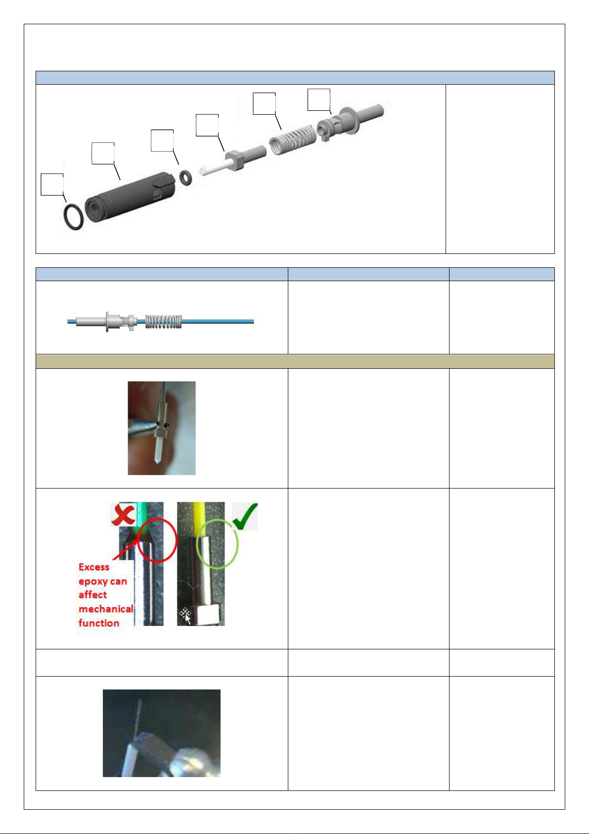
8Terminus assembly
Assembly steps
Com onents list :
A – Housing O-Ring
B – Termini Housing
C – Ferrule O-Ring
D – Ferrule
E – S ring
F – Termini Closure
Picture
Process
Tools
Slide over the cable :
-the Termini Closure “F”
-the S ring “E”
Prepare the cable accordin to strippin dimension from the relevant section.
Insert e oxy into the Ferrule “D”
until a little dro a ears at the
ferrule end.
Carefully insert the fiber into the
back of the Ferrule “D and make
sure the buffer slides inside the
ferrule the buffer bottoms on the
ceramic.
Extended Working
Life, 2-Part E oxy,
2.5 Gram Packet
Su lier : FIBER
OPTIC CENTER
Ref : ET383ND-2.5G
Remove any excess e oxy from
the assembly
Cure
the
e oxy
120 +10/
-
20[°C]
during 20min.
Cleave fiber
Scribe Tool
A
B
C
D
E
F

Assembly instructions rev. 6.1
16
This document is the property of Fischer Connectors.
This document must not be reproduced or distributed, in whole or in part, without prior written permission of Fischer Connectors.
Position
the
Ferrule
O
-
ring
“
C”
on
the Ferrule “D” as shown on the
to left icture.
Slide the S ring “E” and Termini
Closure “F” at the back of the
Ferrule “D” and assemble them
into the Termini Housing “B”.
Position
the
Housing O
-
ring “A
”
on the Termini Housing “B” as
shown on the left icture.
Assembly instructions rev. 6.1
17
This document is the property of Fischer Connectors.
This document must not be reproduced or distributed, in whole or in part, without prior written permission of Fischer Connectors.
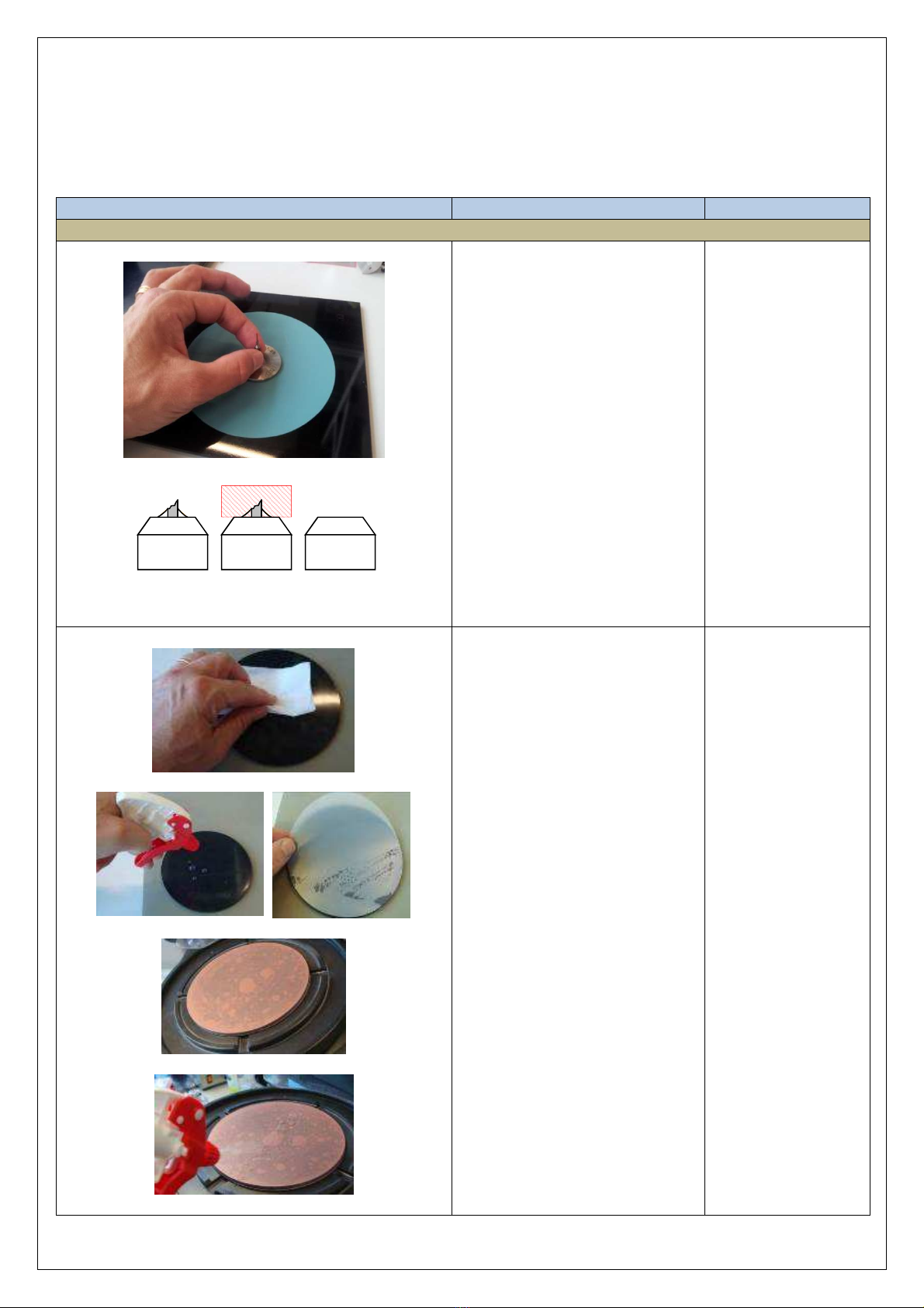
9Polishing
It is recommended olishing the fiber using a olishing machine.
Polish the fiber according to the machine manufacturer’s instructions.
Picture
Process
Tools
PC termini
Step1 : Air polish
Holding the olishing bushing and
terminus, lace the olishing
bushing on the film.
Using light ressure on the
ferrule, olish the endface of the
ferrule in a small circular motion.
Polishing
film:
9µm Silicon
carbide
Polishing Pad :
N/A
Lubricant: N/A
Tool: FO-10090
Clean the olishing ad with
demineralized water and lint-free
cloth, from the center outwards.
S ray some demineralized water
on the olishing ad and lace
the olishing film, starting at
edges of the olishing ad.
S ray abundantly demineralized
water on the olishing film.
A rès
cleave
Air
Polish
A rès
Air
Polish

Assembly instructions rev. 6.1
18
This document is the property of Fischer Connectors.
This document must not be reproduced or distributed, in whole or in part, without prior written permission of Fischer Connectors.
Step 2 :
Polish the termini with 5µm
Silicon carbide olishing film,
until no eri heral chi s are
visible.
Do not remove more than 100
µm.
Polishing
film
:
5µm Silicon
carbide
Polishing Pad :
90 duro black
Lubricant: DI-
water
Fixture tool: FO-
10019
Wi e abundantly the olishing
tool holding the termini with
demineralized water and clean it
carefully with a lint-free cloth.
Use an air ressure gun to remove
residual water.
Clean the olishing ad with
demineralized water and lint-free
cloth, from the center outwards.
S ray some demineralized water
on the olishing ad and lace
the olishing film, starting at
edges of the olishing ad.
S ray abundantly demineralized
water on the olishing film.
Step 3
:
Polish the termini with 1µm
Diamond olishing film in an 8
attern motion (or attern of the
olishing machine).
Polishing
film
:
1µm Diamond
Polishing Pad: 80
duro green
Lubricant: DI-
water
Fixture tool: FO-
10019

Assembly instructions rev. 6.1
19
This document is the property of Fischer Connectors.
This document must not be reproduced or distributed, in whole or in part, without prior written permission of Fischer Connectors.
Wi e abundantly the olishing
tool holding the termini with
demineralized water and clean it
carefully with a lint-free cloth.
Use an air ressure gun to remove
residual water.
Clean the olishing ad with
demineralized water and lint-free
cloth, from the center outwards.
S ray some demineralized water
on the olishing ad and lace
the olishing film, starting at
edges of the olishing ad.
S ray abundantly demineralized
water on the olishing film.
Step 4
:
Polish the termini with
AngstromLa Final Polish SiO2 in
an 8 attern motion.
Do not clean the polishin tool
after this step, to avoid creatin
scratches on the polished
ferrule.
Polishing film
:
AngstromLa
Final Polish SiO2
Polishing Pad: 80
duro green
Lubricant: DI-
water
Fixture tool: FO-
10019
Assembly instructions rev. 6.1
20
This document is the property of Fischer Connectors.
This document must not be reproduced or distributed, in whole or in part, without prior written permission of Fischer Connectors.
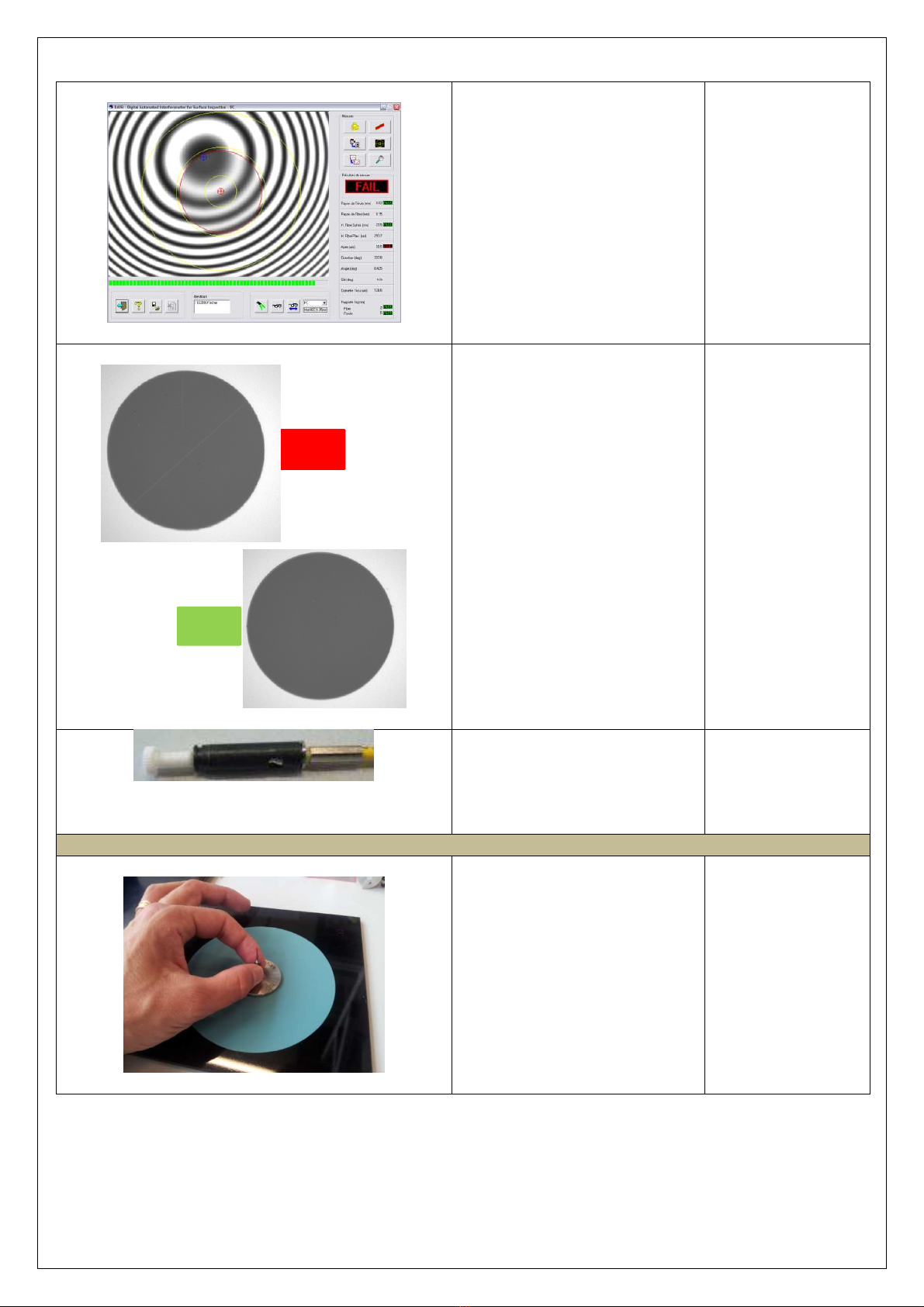
Geometrical control
:
•Ferrule Radius[mm]:
Min 5 - Max 12
•Apex Offset[um]:
Min 0.0 – Max 50.0
If fail, re eat from ste 3.
Fiber core ins ection
:
Examine the endface of the
ferrule for scratches according to
left ictures.
If fail, re eat from ste 4.
If not installing the connector
immediately, install a rotective
cover onto terminus to revent
contamination to the endface of
the ferrule.
8°
APC
termini
Step1 : Air polish
Holding the olishing bushing and
terminus, lace the olishing
bushing on the film.
Using light ressure on the
ferrule, olish the endface of the
ferrule in a small circular motion.
Polishing
film:
9µm Silicon
carbide
Polishing Pad :
N/A
Lubricant: N/A
Tool: FO-10090
NOK
OK
Table of contents
Other Fischer Connectors Cables And Connectors manuals

Fischer Connectors
Fischer Connectors FOH User manual

Fischer Connectors
Fischer Connectors MiniMax MR1 W Series User manual

Fischer Connectors
Fischer Connectors FO2-4 User manual

Fischer Connectors
Fischer Connectors MINIMAX SERIES User manual

Fischer Connectors
Fischer Connectors ULTIMATE SERIES User manual

Fischer Connectors
Fischer Connectors A004-3 User manual


