manuals.online logo
Brands
  1. Home
  2. •
  3. Brands
  4. •
  5. Fisher & Paykel
  6. •
  7. Range
  8. •
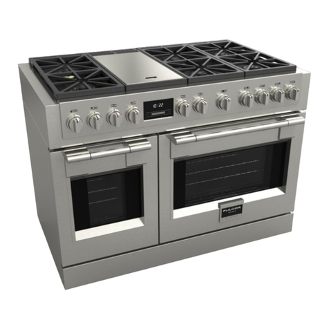
  9. Fisher & Paykel OR24SDMBGX2-N User manual

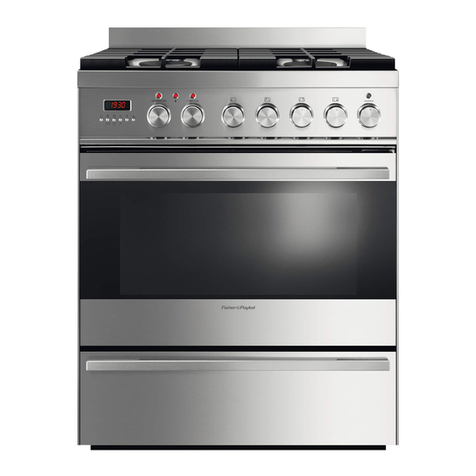
Fisher & Paykel OR24SDMBGX2-N User manual

Other manuals for OR24SDMBGX2-N

1

Other Fisher & Paykel Range manuals

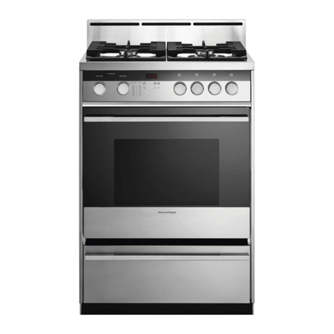
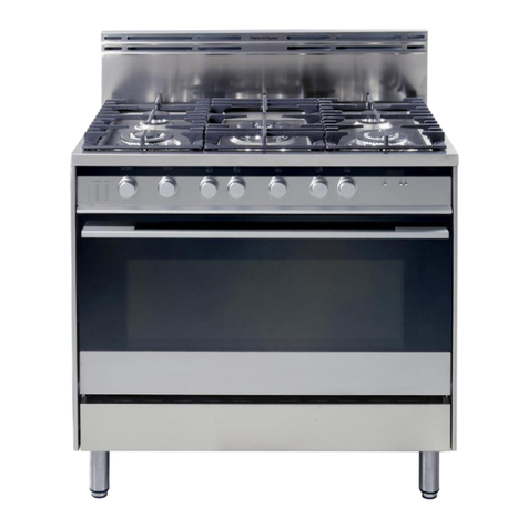
Fisher & Paykel OR24SDMBGX User manual

Fisher & Paykel

Fisher & Paykel OR24SDMBGX User manual

Fisher & Paykel OR36SDBMX1 Operating instructions

Fisher & Paykel

Fisher & Paykel OR36SDBMX1 Operating instructions

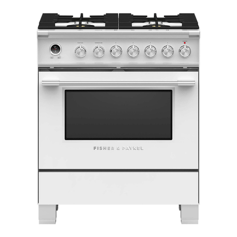
Fisher & Paykel OR30SDPWGX User manual
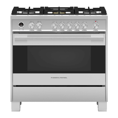
Fisher & Paykel

Fisher & Paykel OR30SDPWGX User manual

Fisher & Paykel RDV2304LN User manual

Fisher & Paykel

Fisher & Paykel RDV2304LN User manual

Fisher & Paykel CG604CLPX2 User manual

Fisher & Paykel

Fisher & Paykel CG604CLPX2 User manual

Fisher & Paykel OR36SDBGX User manual

Fisher & Paykel

Fisher & Paykel OR36SDBGX User manual

Fisher & Paykel OR36SDBMX Operation instructions

Fisher & Paykel

Fisher & Paykel OR36SDBMX Operation instructions

Fisher & Paykel OR36LDBGX User manual

Fisher & Paykel

Fisher & Paykel OR36LDBGX User manual

Fisher & Paykel 7 Series User manual

Fisher & Paykel

Fisher & Paykel 7 Series User manual

Fisher & Paykel OR90SCG1LX User manual

Fisher & Paykel

Fisher & Paykel OR90SCG1LX User manual

Fisher & Paykel RGV3-485GD User manual

Fisher & Paykel

Fisher & Paykel RGV3-485GD User manual

Fisher & Paykel RIV3-365 User manual

Fisher & Paykel

Fisher & Paykel RIV3-365 User manual

Fisher & Paykel OR24SDMBGX2 User manual

Fisher & Paykel

Fisher & Paykel OR24SDMBGX2 User manual

Fisher & Paykel OR36SDBMX1 User manual

Fisher & Paykel

Fisher & Paykel OR36SDBMX1 User manual

Fisher & Paykel OR30SDPWGX User manual

Fisher & Paykel

Fisher & Paykel OR30SDPWGX User manual

Fisher & Paykel OR24SDPWSX User manual

Fisher & Paykel

Fisher & Paykel OR24SDPWSX User manual

Fisher & Paykel RIV3486 User manual

Fisher & Paykel

Fisher & Paykel RIV3486 User manual

Fisher & Paykel RA535 Series Owner's manual

Fisher & Paykel

Fisher & Paykel RA535 Series Owner's manual

Fisher & Paykel OR30SNDGX Mounting instructions

Fisher & Paykel

Fisher & Paykel OR30SNDGX Mounting instructions

Fisher & Paykel OR36SDG User manual

Fisher & Paykel

Fisher & Paykel OR36SDG User manual

Fisher & Paykel OR90SCG6B1 User manual

Fisher & Paykel

Fisher & Paykel OR90SCG6B1 User manual

Fisher & Paykel OR36SCG4 User manual

Fisher & Paykel

Fisher & Paykel OR36SCG4 User manual

Fisher & Paykel OR60SDBGFX2 User manual

Fisher & Paykel

Fisher & Paykel OR60SDBGFX2 User manual

Fisher & Paykel OR30SCG User manual

Fisher & Paykel

Fisher & Paykel OR30SCG User manual

Popular Range manuals by other brands

Maytag MGR5875QDW - 30 Inch Gas Range Use and care guide

Maytag

Maytag MGR5875QDW - 30 Inch Gas Range Use and care guide

Frigidaire FFGF3024SS use & care

Frigidaire

Frigidaire FFGF3024SS use & care

Capital Precision Series GCR484W Specifications

Capital

Capital Precision Series GCR484W Specifications

Officine Gullo GGS8P Installation and use instruction

Officine Gullo

Officine Gullo GGS8P Installation and use instruction

LG LSD4913 Series owner's manual

LG

LG LSD4913 Series owner's manual

Kenmore 4101 - Elite 30 in. Slide-In Electric Range installation instructions

Kenmore

Kenmore 4101 - Elite 30 in. Slide-In Electric Range installation instructions

Moffat Blue Seal Evolution G576 Technical data sheet

Moffat

Moffat Blue Seal Evolution G576 Technical data sheet

CornuFé C1NF user guide

CornuFé

CornuFé C1NF user guide

GE JGS650SEFSS Dimensions and installation information

GE

GE JGS650SEFSS Dimensions and installation information

LG LDG3015ST Manual De Propietario

LG

LG LDG3015ST Manual De Propietario

Whirlpool RF350PXP Use and care guide

Whirlpool

Whirlpool RF350PXP Use and care guide

Samsung FCQ321HTUW Service manual

Samsung

Samsung FCQ321HTUW Service manual

Kenmore 790.45712 Use & care guide

Kenmore

Kenmore 790.45712 Use & care guide

Wolf CHR CHSSR owner's manual

Wolf

Wolf CHR CHSSR owner's manual

Smeg Built-in Microwave Oven Instructions for the user

Smeg

Smeg Built-in Microwave Oven Instructions for the user

Zanussi ZCG054G user manual

Zanussi

Zanussi ZCG054G user manual

GE JCSS630 quick start guide

GE

GE JCSS630 quick start guide

Samsung NX58M9960P series installation manual

Samsung

Samsung NX58M9960P series installation manual

manuals.online logo
manuals.online logoBrands
  • About & Mission
  • Contact us
  • Privacy Policy
  • Terms and Conditions

Copyright 2025 Manuals.Online. All Rights Reserved.

OR24SDMBGX2-N
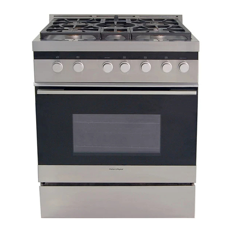
24'' Gas Range - MSRP: $3,109.00
Selected Model
Model number OR24SDMBGX2-N
Exterior Appearence
Color Appearance Stainless Steel
Design Style European
Grates Robust Cast-iron
Features
Configuration 4 Burners
Energy type Gas
Cooktop Burners Sealed
Fuel Type Natural Gas (NG) or Propane (LP)
Control Location Upfront
Control Type Rotative Knobs
Capacity
Oven Capacity 2.5 pi.cu
Cooktop Features
Ignition System Electronic with automatic reignition
Cooktop Surface Stainless Steel
Oven Features
Convection Technology Traditional Convection
Bake Burner 13000 BTU
Oven Cleaning Type Manual
Oven Modes 4
Broil Element 8500 BTU
Oven Rack 2
Shelves Positions 3
Oven door features Cool Touch Triple Glazed Door
Beneath Oven Cavity Storage
Removable door and glasses Yes
Installation
Installation Type Built-in (Flush with the Cabinets) or Free
Standing
Burner ratings
High Performance Double Burner 12000 BTU
6000 BTU
Simmer Burner 3500-1000 BTU
Exterior Dimensions
Overall Height (in.) 35 5/8'' - 36 3/8''
Overall Width (in.) 23 7/8''
Overall Depth (in.) 24''
Electrical Requirements
Volts; Hertz; Amps 120V; 60Hz; 0.1 Amp
Accessories (Included)
Wok Stand Included
5 inch. Backgurad Included
Rotisserie Pan Included
LP Conversion Kit Included
Warranty
2 Years full waranty Entire Appliance, In-Home Parts & Labour
Powered by TCPDF (www.tcpdf.org)
The information contained herein is based on sources that we believe to be reliable, but is not guaranteed by us,
may be incomplete or may change without notice
6
(303 mm)
(303 mm)
11" 15/16
11" 15/16
(150 mm)
5" 57/64
installation

PROXIMITY TO SIDE CABINETS
1. This range may be installed directly adjacent to existing 36" (914 mm) high base
cabinets.
Range dimensions:
• width: 23” 7/8 (606.5 mm)
• depth: 24” 5/64 (611.6 mm)
• height (without backguard): MIN 35” 7/16 (900 mm) - MAX 36” 7/32 (920 mm)
• backguard (height): 4” 7/16 (113 mm)
Gas line opening:
Wall - 5” 57/64 (150 mm) from the floor; 11” 15/16 (303 mm) from the rear left side
of the range.
Grounded outlet: the electric cord with 3-prong ground plug has a length of 72”
(1830 mm). Grounded outlet should be located 5” 57/64 (150 mm) from the floor
and 11” 15/16 (303 mm) from the rear right side of the range.
2. The range CANNOT be installed directly adjacent to sidewalls, tall cabinets, tall
appliances, or other side vertical surfaces above 36” (914 mm) high.
There must be a minimum of 3” (76 mm) side clearance from the range to such
combustible surfaces TO THE LEFT above the 36” (914 mm) high countertop; or
there must be a minimum of 11” 13/16 (300 mm) side clearance from the range to
such combustible surfaces TO THE RIGHT above the 36” (914 mm) high counter-
top.
IMPORTANT: One side (left or right) above the 36” (914 mm) high countertop
must always be kept clear.
3. The maximum upper cabinet depth recommended is 13” (330 mm). Wall cabinet
above the range must be a minimum of 30” (762 mm) above the countertop for a
width of minimum 24” (609.6 mm): it has to be centred with the range. Side wall cab-
inets above the range must be a minimum of 18” (457 mm) above the countertop.
4" 7/16
(113 mm)
(606.5 mm)
23" 7/8
24" 5/64
MIN 35" 7/16 (900 mm)
MAX 36" 7/32 (920 mm)
(611.6 mm)
Fig. 1.1
GAS AND ELECTRIC CONNECTION
Dotted line showing the position
of the range when installed
Area for GAS connection
Area for ELECTRICAL
connection
Fig. 1.2
1
7

A
B
A
(914 mm)
36" 30" min.
(762 mm)
(457 mm)
18" min.
0"
0"
(0 mm)
(0 mm)
20" min. (500 mm)
11"
13/16
min. (300 mm)
13" max. (330 mm)
0"
(0 mm)
3"
min. (76 mm)
13" max. (330 mm)
(914 mm)
36"
0"
(0 mm)
20" min. (500 mm)
30" min.
(762 mm)
(457 mm)
18" min.
PROXIMITY TO SIDE CABINETS
Fig. 1.3b
ASSEMBLING THE BACKGUARD
It is mandatory to install the backguard
Assemble the backguard as shown in figure 1.5:
• Screw the 2 screws “A” interposing the spacers.
• Screw the central screw “B”.
OVEN VENT
Fig. 1.3a
Fig. 1.4
Fig. 1.5
1
8

LEVELLING THE RANGE
The range is equipped with 4 LEVELLING FEET (SUPPLIED IN A SEPARATE KIT) and
may be levelled by screwing or unscrewing the feet with a spanner (fig. 1.8).
It is important to observe the directions of figures 1.6, 1.7a, 1.7b.
+ 8 mm
+ 5/16"
+ 8 mm
+ 5/16"
0 mm
0"
+ 20 mm
+ 25/2"
Fig. 1.6
Fig. 1.7a Fig. 1.7b
Fig. 1.8
ANTI-TIP STABILITY DEVICE INSTALLATION INSTRUCTIONS
1. The anti-tip bracket has to be attached as shown on figure below (only rear right
side), it has to be fixed on the floor and on the rear wall by no. 4 (four) suitable screws
(not supplied).
2. After fixing the anti-tip bracket, slide range into place. Be sure the rear right foot
slides under the anti-tip bracket attached.
==
(260 mm)
10" 15/64
Dotted line showing the position
of the range when installed
ANTI-TIP STABILITY
DEVICE FIXING
Rear right
feet of range
Fig. 1.9
Anti-tip stability
device
Supplied with the range
in a separate kit
YOU MUST USE STABILITY
ANTI TIP BRACKET TO
PREVENT UNIT FROM
TIPPING.
1
Supplied with the range
in a separate kit