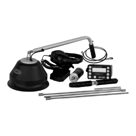
Fisher Labs XLT-30 User manual

XLT-30
Operating Manual
Acoustical Leak Detector
F I S H E R R E S E A R C H L A B O R A T O R Y
OPTION A
with BIG FOOT
OPTION B
with NEW MULTI-SENSOR
OPTION C
with LITTLE FOOT
www.calcert.com [email protected]1.800.544.2843 0
5
10
15
20
25
30

INTRODUCTION
professional.
CONTENTS
Introduction ...............................................................................pg. 2
Headphones..............................................................................pg. 2
............................................................................
Control Panel.............................................................................
Operating Instructions ..............................................................pg. 8
..............................................................
............................................................................
2
USING HEADPHONES
clearly, particularly if searching in a noisy location. For safety
other dangers are present. This device is to be used with
interconnecting cables/headphone cables shorter than three
www.calcert.com [email protected]1.800.544.2843 0
5
10
15
20
25
30

1
3
INSTRUMENT SET
1
1
1
2
6
3
4
5
6
3
5
4
2A
6
4
8
8
8
2B
OPTION A
OPTION C
OPTION B
5A
7
7
www.calcert.com [email protected]1.800.544.2843 0
5
10
15
20
25
30

1. Control Box
housing. The function of each control is described in the section entitled
“Faceplate and Controls”.
2. Big Foot Sensor - OPTION A
vent outside sounds from interfering with the sounds from the buried pipe.
Press and hold the red button near the handle to mute the audio from
the probe and suppress loud sounds when the probe is moved.
2A. Little Foot Assembly - OPTION C
assembly is normally used for leak detection inside buildings. Mute is
activated by pressing the button in front of the Little Foot Assembly.
2B. Multi-Sensor - OPTION B
extremely compact design, Fisher has achieved higher performance,
improved audio clarity, improved sensor electronics, and better sensitivity
leak detection.
3. Hydrophonic Cylinder Probe
This probe is a direct contact probe designed to make direct connection
to the pipe, or any portion of the pipe that is accessible. Used in any
Another feature of the Cylinder Probe is the ability to listen to pipe noise
in pipes that are buried in turf, or soft surfaces. Accurate pipe location
as possible.
On top of the Cylinder Probe is a three position toggle switch for mute,
listen, and momentary listen. As with all mute controls, learn to use them
wisely.
connector with a wrench as to not let it twist. Twisting of that connector
could damage wiring on the inside of the probe.
INSTRUMENT SET
4
www.calcert.com [email protected]1.800.544.2843 0
5
10
15
20
25
30

5
4. Sound
Rods
ous lengths for direct or indirect contact to pipes.
5. T-Handle
This handle is used primarily with the Cylinder Probe and the sound
rods.
5A. Multi-Sensor Handle
6. Headphones
These headphones are designed to deliver the clearest sound with the
least distortion. The Volume knob can be used to adjust the audio level.
to the factory presets.
7. Probe Cable (Option A & C)
various probes. Make sure the jack is fully inserted and the lock nut is
hand tightened.
around the faceplate. There are two slots for attaching an adjustable
strap that hangs around the neck of the user.
INSTRUMENT SET
www.calcert.com [email protected]1.800.544.2843 0
5
10
15
20
25
30

CONTROL PANEL
POWER
.
LIGHT
Press Light pad to turn the back light on or off. Prolonged use of the back
VOLUME
Use the headphones volume knob to reduce audio as desired.
NOTCH
This control allows the user to mask or reject a small range of frequency
be moved with the arrow keys.
FILTER
6
www.calcert.com [email protected]1.800.544.2843 0
5
10
15
20
25
30

7
response in the higher areas of the frequency range. Use the arrow keys
to increase or decrease this frequency response range.
The arrow keys are used to increase or decrease this frequency response
range.
Select. This mode allows tuning to the frequency that gives the user the
best response. The arrow keys are used to move the cursor, selecting a
narrow frequency band of choice
HOLD/MUTE
This dual purpose button is both a mute control and a peak hold
reset control.
user. There is also a control on all listening microphones. Learn to use
this control to prevent excessive noise to your ears when the probes are
moved.
recorded. This reading can be reset by pressing this pad. Resetting the
ARROW KEYS
RESUME
CONTROL PANEL
www.calcert.com [email protected]1.800.544.2843 0
5
10
15
20
25
30

OPERATING INSTRUCTIONS
Set Up
second warm up before the touch pads are functional. During this time,
shut down to allow you to complete a job.
is at the midway point. The display screen will show the sound intensity
pads to increase or decrease the volume. The display screen will show
the volume level in a graph form. Press the RESUME pad to exit volume
increase your ability to hear the leak sound.
8
www.calcert.com [email protected]1.800.544.2843 0
5
10
15
20
25
30

9
Use of the Notch Filter
Occasionally, you may come across a sound that may be
masking or covering your ability to adequately hear any leaks.
This may be caused by nearby motors, fans, or many other
reject feature, that will assist in eliminating that sound from your
frequency range.
cursor to the point where the annoying sound is eliminated or at
its weakest. Depress the RESUME pad to set the notch function.
Now you can choose the type of Filter you wish to use AND still
Use of the Multi-Sensor (OPTION B)
Unlike our other sensor, this new sensor was designed for locating
leaks in all types of surface conditions. The new sensor construction
will allow leak detection to be performed on hard surfaces such
as concrete, asphalt, tile, etc, as well as listening to water leaks
under turf or soft surfaces.
OPERATING INSTRUCTIONS
sensor sensor is used to pick
up the vibrations generated
by a buried ruptured pipe
located underneath sidewalks
or paved streets. The rubber
h o u s i n g d i a p h r a g m i s
designed to reduce external
sounds while the sensor rests
on a hard surface and detects
th e vibr at i o ns tra vel ing
underground.
www.calcert.com [email protected]1.800.544.2843 0
5
10
15
20
25
30

NOTE: This equipment has been tested and found to comply with the limits
limits are designed to provide reasonable protection against harmful
interference in a residential installation. This equipment generates, uses,
and can radiate radio frequency energy and, if not installed and used
in accordance with the instructions, may cause harmful interference to
will not occur in a particular installation. If this equip ment does cause
determined by turning the equipment off and on, the user is encouraged
to try and correct the interference by one or more of the following
to which the receiver is connected.
10
connection to a pipe, or listening to buried
pipes located in soft ground or under a
unit. Using a threaded spacer provided on
the extension handle, carefully attach it
directly onto our sensor probe. Assemble
extension handle and probe handle
sections together. Sound rods are then
secured to the threaded coupler on the
determined on its application.
USE OF THE MULTI-SENSOR (OPTION B)
SPECIFICATIONS
www.calcert.com [email protected]1.800.544.2843 0
5
10
15
20
25
30

Fisher Research Laboratory shall in no event be liable for any direct, incidental, conse
quential or indirect damages.
SPECIFICATIONS
11
Filter types and frequency ranges:
.......................
.......................
.....................
...................
Indication of output:
............................
............................. LCD bar graph display w/2 digit numerical read out.
.................... Splash proof
..................................... Automatic
.............
.....................................
WEIGHT
Option “A” Option “B” Option “C”
ACCESSORIES:
Option “A” Option “B” Option “C”
Little Foot
STANDARD EQUIPMENT:
Option “A” Option “B” Option “C”
Plastic case Plastic case Plastic case
Operation manual Operation manual Operation manual
Control unit Control unit Control unit
Probe
Carry Strap Sound Rods Carry Strap
Sound Rods Sound Rods
www.calcert.com [email protected]1.800.544.2843 0
5
10
15
20
25
30

QUALITY
Fisher detectors are renowned for their quality.
Each detector is hand crafted in the USA with pride
P E R F O R M A N C E
The worldwide underground utility industry relys on Fisher.
Our instruments are durable, dependable, and locate deeper.
R E P U T A T I O N
over 70 years, the Fisher logo has been a mark of excellence.
2 - YEAR LIMITED WARRANTY
Fisher believes in the products we produce and backs this belief
with a 2 year limited warranty.
Proof of purchase is required to make a claim under this warranty.
NOTE TO FOREIGN COUNTRY CUSTOMERS
This warranty may vary in other countries, check with your
distributor for details.
Factory warranty follows the channel of distribution.
Warranty does not cover shipping costs.
S E R V I C E
Fisher is committed to providing you, our valued customer, with
superior service. Each and every instrument is rigidly tested
and carefully inspected during assembly and before shipment.
Should you have any questions or problems, contact:
FISHER RESEARCH LABORATORY
FRL#8700721
www.calcert.com [email protected]1.800.544.2843 0
5
10
15
20
25
30
Other manuals for XLT-30
1
This manual suits for next models
4
Other Fisher Labs Security Sensor manuals
Popular Security Sensor manuals by other brands
Broadcast Tools
Broadcast Tools B031 Handbook

X10
X10 MS18A user manual

PCB Piezotronics
PCB Piezotronics ICP M102B06 Installation and operating manual

DSC
DSC PG9933 Installation and operating instructions

Leedarson
Leedarson Motion Sensor Pet Immunity Z-Wave 700 quick start guide

Feig Electronic
Feig Electronic OBID i-scan ID ISC.ANT1300/680-A Installation