Fisher Scientific 13-986-127G User manual

Isotemp Chromatography and General
Purpose Laboratory Refrigerators
Chromatography Refrigerator Models
13-986-127G/GR/GA 13-986-127GHK
13-986-133G/GR/GA 13-986-133GHK
13-986-138G/GR/GA 13-986-138GHK
13-986-145G/GR/GA 13-986-145GHK
13-986-149G/GR/GA 13-986-149GHK
13-986-172G/GR/GA 13-986-172GHK
General Purpose
Laboratory Refrigerator Models
13-986-227R/G/RR/RA/GR/GA 13-986-227GHK
13-986-238G/GR/GA 13-986-238GHK
13-986-245G/GR/GA 13-986-245GHK
13-986-249R/G/RR/RA/GR/GA 13-986-249GHK
13-986-272G/GR/GA 13-986-272GHK
104416 • 9/20/06

2
Introduction ............................................................................................................................................................................3
Unpacking and Installation ....................................................................................................................................................4
Unpacking........................................................................................................................................................................4
Visible Loss or Damage ..................................................................................................................................................4
Concealed Loss or Damage............................................................................................................................................4
Packing List ....................................................................................................................................................................5
Selecting a Location ........................................................................................................................................................5
Leveling the Unit..............................................................................................................................................................5
Door Handles ..................................................................................................................................................................6
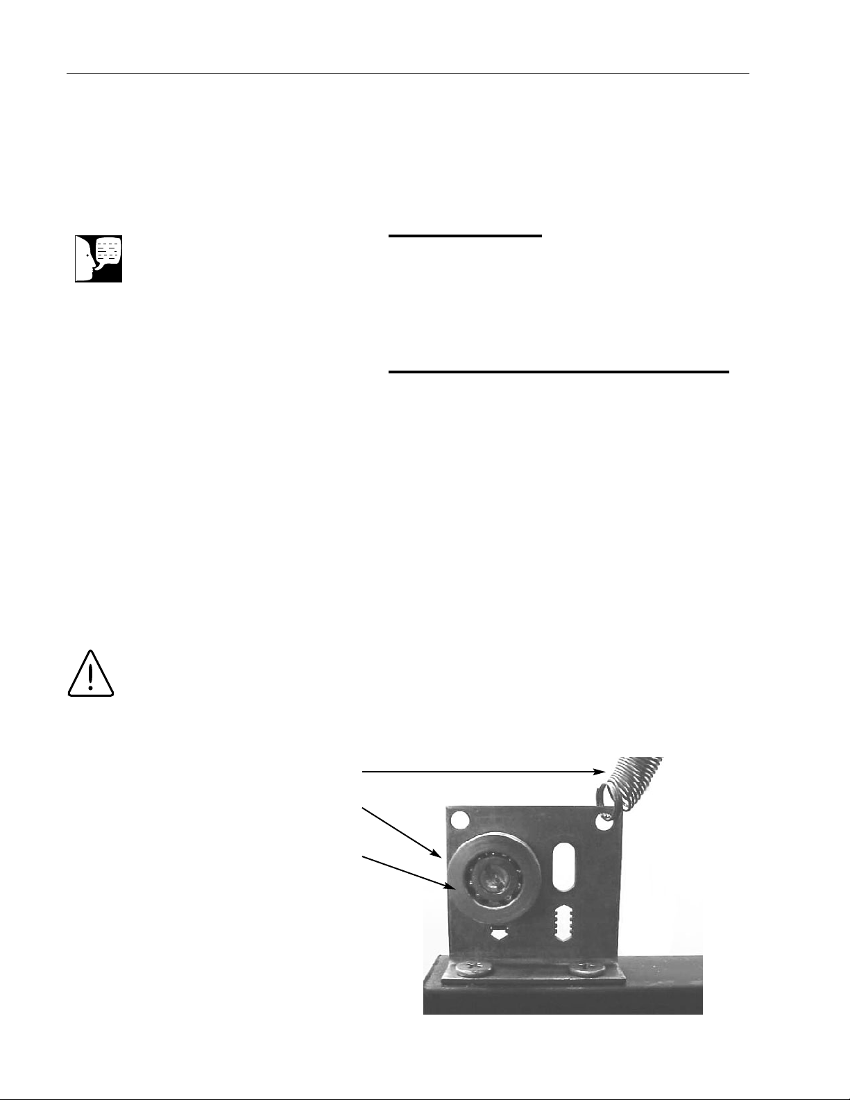
Door Removal and Adjustment........................................................................................................................................6
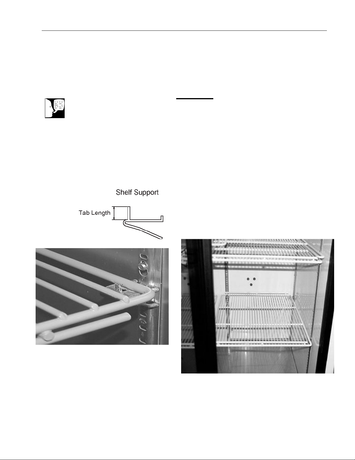
Shelves............................................................................................................................................................................7
Electrical Connection ......................................................................................................................................................8
Operation ................................................................................................................................................................................9
Controls Layout ..............................................................................................................................................................9
Temperature Controller....................................................................................................................................................9
Setting the Temperature ........................................................................................................................................10
Unit Select ..............................................................................................................................................................10
Calibration Offset....................................................................................................................................................10
Hold-Off Time ........................................................................................................................................................11
Error Codes ..................................................................................................................................................................11
Fluorescent Lamps........................................................................................................................................................11
Convenience Outlet ......................................................................................................................................................12
Manual/Automatic Condenser Fan................................................................................................................................12
Troubleshooting ....................................................................................................................................................................13
Maintenance ........................................................................................................................................................................14
Cabinet Cleaning ..........................................................................................................................................................14
Cleaning the Condensor................................................................................................................................................14
Condensate Evaporator Pan ........................................................................................................................................14
Replacement Parts ..............................................................................................................................................................15
Specifications........................................................................................................................................................................16
Performance Characteristics ........................................................................................................................................16
Power Requirements ....................................................................................................................................................16
Wiring Diagrams ..................................................................................................................................................................17
Warranty ..............................................................................................................................................................................20
Table of Contents

3
Your satisfaction and safety are important to Fisher
Scientific, a complete understanding of this unit is neces-
sary to attain these objectives.
As the ultimate user of this apparatus, it is your responsi-
bility to understand its proper function and operational
characteristics. This instruction manual should be thor-
oughly read and all operators given adequate training
before attempting to place this unit in service. Awareness
of the stated cautions and warnings, and compliance with
recommended operating parameters - together with main-
tenance requirements - are important for safe and satis-
factory operation. The unit should be used for its intended
application; alterations or modifications will void the
Warranty.
Introduction
Warning
As a routine laboratory precaution,
always wear safety glasses when
working with this apparatus.
Warning
This product is not intended, nor can it
be used, as a sterile or patient con-
nected device. In addition, this appara-
tus is not designed for use in Class I,
II or III locations as defined by the
National Electrical Code, unless other-
wise noted.
Warning
Warnings alert you to a possibility of
personal injury.
Caution
Cautions alert you to a possibility of
damage to the equipment.
Note
Notes alert you to pertinent facts and
conditions.
Hot Surface
Hot surfaces alert you to a possibility
of personal injury if you come in con-
tact with a surface during use or for a
period of time after use.
Alert Signals
DANGER: RISK OF CHILD ENTRAP-
MENT. BEFORE YOU THROW AWAY
YOUR OLD REFRIGERATOR OR
FREEZER:
•TAKE OFF DOORS
•LEAVE THE SHELVES IN THE
PLACE SO THATCHILDREN MAY
NOT EASILY CLIMB INSIDE.

4
Unpacking
Save all packing material if apparatus is received dam-
aged. This merchandise was carefully packed and thor-
oughly inspected before leaving our factory.
Responsibility for its safe delivery was assumed by
the carrier upon acceptance of the shipment; there-
fore, claims for loss or damage sustained in transit
must be made upon the carrier by the recipient as fol-
lows:
Visible Loss or Damage
Note any external evidence of loss or damage on the
freight bill, or express receipt, and have it signed by the
carrier’s agent. Failure to adequately describe such exter-
nal evidence of loss or damage may result in the carrier’s
refusing to honor your damage claim. The carrier will sup-
ply the form required to file such a claim.
Concealed Loss or Damage
Concealed loss or damage refers to loss or damage,
which does not become apparent until the merchandise
has been unpacked and inspected. Should either occur,
make a written request to the carrier’s agent within 15
days of the delivery date; then file a claim with the carrier
since the damage is the carrier’s responsibility.
If you follow the above instructions carefully, we will guar-
antee our full support of your claim to be compensated for
loss from concealed damage.
DO NOT – FOR ANY REASON – RETURN THIS UNIT
WITHOUT FIRST OBTAINING AUTHORIZATION
Unpacking and Installation

Packing List
The following items are packed in the envelope located
inside the refrigerator chamber. If any of the following
items are not present, report the missing item to your
local Fisher representative.
1. Warranty Card
2. Instruction Manual
3. Door Lock Key
4. Power Switch Key
5. Chart Recorder Instructions
Selecting a Location
Choose a location for the refrigerator that will provide at
least three inches of clearance between the cabinet
and any adjacent vertical surface at the sides and rear.
Appropriate electrical power must be available. Locate
the refrigerator within 6 feet of the power outlet so that no
extension cord is required.
Leveling the Unit
The refrigerator must be level in order to provide ade-
quate condensation drainage as well as proper door
alignment and operation. The refrigerator should be in its
final operating location and set so that it is firmly posi-
tioned on the floor. There are four leveling screws, one on
each corner. Level the cabinet front to rear and side-
to-side using the corner leveling screws. The leveling
screws are accessed by removing the base grille, as
described below:
1. Remove the lower grille attaching screws.
2. Grasp the grille with both hands.
3. Tilt the lower end of the base grille toward you.
4. Pull grille away from the refrigerator.
5
UNPACKING AND INSTALLATION

Door Handles
(Swinging Door Models Only)
Door handles are packed inside each refrigerator. To
mount the handle, lift the door gasket behind the two
screws on the front of the door. Attach handle with offset
away from the cabinet corner and tighten the screws.
Door Removal and Adjustment
(Sliding Door Models Only)
Each door has its own closing spring located at the top of
the door track. Each spring is set for proper tension. If
adjustment is required:
1. Check for cabinet level (see above).
2. Remove the door(s) by lifting it and sliding about
half way open. The roller will fall into a gap in
the upper track. While maintaining upward
pressure on the door, pull the bottom outward
until it clears the bottom track.
3. Adjust the location of the door rollers in the
roller brackets (above door) as shown by loos-
ening the lock nut on the back of the roller
bracket and moving the roller up or down.
4. The spring tension can be adjusted by moving
the spring to the outside hole of the bracket or
by snipping a portion of it off and then refasten-
ing it to the bracket.
UNPACKING AND INSTALLATION
Note
The refrigerator must be level in order
to provide adequate condensation
drainage as well as proper door align-
ment and operation. The refrigerator
should be in its final operating loca-
tion and set so that it is firmly posi-
tioned on the floor.
Closing spring
Lock nut on back
Roller
Figure 1
Warning
Wear safety glasses before snipping
spring.
6

Shelves
Shipped inside each cabinet are shelves packed in plastic
and a bag of shelf supports. Two different types of shelf
supports are used. The shelf supports have tab lengths
of 1/4 inch and 1/2 inch. The 1/4 inch versions are used
in the front of the shelf (see below) and the 1/2” shelf sup-
ports are used in the rear.
Shelf spacing is adjustable to suit user requirements.
Insert four shelf supports for each shelf into the pilasters
as shown. Note the numbers on the pilasters. Place
supports on the same numbers on each pilaster to ensure
the shelf will be level. Place the shelf on the pilasters as
shown in Fig’s 2 and 3.
Replacement shelves are available individually. See
Replacement Parts for shelf part numbers. Proper shelf
orientation is illustrated in Figure 2.
7
Note
Chromatography units include addi-
tional 1/2 shelves, which can be
used in place of the full shelves.
Figure 2 - Use 1/4” tab length supports on sides
and 1/2” in back.
UNPACKING AND INSTALLATION
Figure 3 - Place shelves at desired height on four
shelf supports.

Electrical Connection
The frequency and nominal voltage requirements for the
unit are specified on the data plate, which is located on
the interiors upper left side. Only plug the unit into a
power source that meets these requirements. Low line
voltage is often the cause of service complaints.
With the unit running, check that the line voltage is
within ±10% of that specified on the data plate.
The power cord of this instrument is equipped with a
three prong (grounding) plug (NEMA 5-15P). This plug
mates with a standard three prong (grounding) wall recep-
tacle (NEMA 5-15R) to minimize the potential of an elec-
trical shock hazard. Chromatography models are
equipped with a (NEMA 5-20P). This plug must mate with
a (NEMA 5-20R).
The customer should have the wall receptacle and circuit
checked by a qualified electrician to verify the receptacle
is properly grounded and meets power requirements
specified on the data plate.
Where a two prong wall receptacle is encountered, it is
the personal responsibility and obligation of the user to
have it replaced with a properly grounded three prong
receptacle.
8
UNPACKING AND INSTALLATION
Caution
Be sure that the power supply is the
same voltage that is specified on the
refrigerator's data plate.
Warning
Insufficient line voltage is often the
cause of compressor start-up failure.
It is strongly recommended that a
dedicated circuit, conforming to the
National Electrical Code, Article 440,
be used for powering the refrigera-
tor..
Warning
DO NOT under any circumstances cut
or remove the third (ground) prong
from the power cord. DO NOT use a
two-prong adapter plug.
Warning
For personal safety this unit must be
properly grounded.
Warning
Do not use an extension cord. Use
of an ungrounded cord or an over-
loaded circuit VOIDS the compres-
sor warranty.

Before operation, become familiar with the refrigerator
controls located on the refrigerator header panel. A layout
of the controls is given below.
Controls Layout
Begin operation by inserting the key into the key switch
located on the header panel. The key switch is packed
inside the envelope, which is shipped in the refrigerator
chamber. Turning the key switch to the ON ( | ) position
will energize the evaporator fans and the digital controller.
Temperature Controller
The digital temperature controller is located on the left
side of the header panel (See Figure 4). When the unit is
initially turned on, the display will indicate current cham-
ber temperature. The temperature units will be indicated
by the °C or °F LED located just to the right of the tem-
perature display. The refrigerator is factory set at 4°C.
When the unit is first energized the evaporator fans will
operate however it will not immediately cool. A 3-minute
compressor delay is programmed into the controller to
provide sufficient time for the evaporator to defrost and to
allow the system pressure time to equalize. When the
delay time is over, the Cool LED will illuminate, the com-
pressor will run and the chamber will cool.
Operation
Warning
If the unit is tilted in excess of 30
degrees, do not apply electrical power
for a minimum of 12 hours.
Warning
This product is NOT approved for stor-
age of flammable or explosive materi-
als. Also, it is NOT approved for use in
hazardous locations containing explo-
sive atmospheres.
I
O
POWER
Light Switch
Units LED'S
Mode LED
Cool LED
Key Switch
Digital Display
Menu Keypad
Up Arrow Keypad Down Arrow
Keypad
Figure 4
9
Note
The compressor requires a 3-minute
delay time between activations. The
unit will not cool during this delay.
The delay is also activated when the
controller is first energized.

10
Setting the Temperature
To change the set temperature, press and release the
Menu keypad once. The display will flash SP and the
Mode LED will be illuminated. The last set temperature
will then be shown in the display. To change the tempera-
ture, press the UP or DOWN arrow key. The adjustable
temperature range is 1 to 12°C (34 to 54°F). When the
desired set temperature is displayed, press the Menu key-
pad to enter the set temperature and activate the Units
Select menu.
Units Select
The second menu selects the units. The refrigerator con-
trol displays temperature in °C or °F. The factory setting
is °C. Starting from the temperature display mode (Mode
LED off), press the Menu key twice. The current temper-
ature units are displayed. To switch between units, press
the UP or DOWN arrow key then press the Menu key to
select. The unit LED will be displayed on the right of the
temperature display.
Calibration Offset
In the event the refrigerator needs to be calibrated, a sim-
ple routine is available to adjust the display and control
point to a referenced standard. To set a temperature off-
set, press and hold the Menu keypad for 5 seconds. The
display will flash oS followed by the last temperature off-
set value. The factory setting is 0. To change the offset
value, press the UP or DOWN arrow key, then press the
Menu key. The value shown in the display will be added
to the previous temperature reading. The display will
then flash Ho.
For Example:
The display indicates 4°C but a reference thermometer in
the refrigerator chamber indicates 6°C. The operator
presses and holds the Menu keypad for 5 seconds, then
changes the display value from 0 to +2 by using the UP
arrow key. Press the Menu key again. Now the display
indicates a chamber temperature of 6°C and the con-
troller begins to cool (as long as 3-min. delay period has
expired) to the desired temperature of 4°C as shown on
the reference thermometer.
OPERATION

Allow an additional 30 to 40 minutes for the refrigerator to
again stabilize. If the display is still inaccurate, repeat the
calibration offset procedure.
Hold Off Time
Following the offset menu is the hold-off (Ho) menu. The
display will momentarily flash "Ho", followed by a number.
The number shown is the delay time in minutes between
compressor activations. Use the UP/DOWN keypads to
change the value.
Increasing the hold-off time will allow additional time for
the evaporator to defrost during the off-cycle. This can
reduce the chance of evaporator freeze-up during times
of high humidity. Pressing the Menu keypad while in the
Ho mode, enters the hold-off time displayed, and returns
controller operation to the temperature display mode.
Error Codes
Error codes indicate when the controller is sensing a
problem. A description of each is given below. See the
Troubleshooting Table for additional information on error
codes.
E1 Open sensor.
E2 Under temperature. Temperature at sensor is
less than –36°C.
E3 Over temperature. Temperature at sensor is
greater than 37°C.
Fluorescent Lamps
The interior lamp is controlled by a rocker switch on the
header panel. This light may be operated any time the
cabinet power is turned on at the keyed power switch. If
the interior lamp fails, replace with the same size and
wattage lamp. DO NOT USE REDUCED WATTAGE
LAMPS. The reduced wattage lamps generally fail to
light below 60°F (15°C).
11
OPERATION
Caution
INCREASING the offset value
DECREASES the temperature at
which the system controls. If the off-
set is inadvertently set too high, the
chamber’s control temperature can fall
below zero and cause evaporator
freeze-up. This is caused by the
evaporator temperature not rising
above 0°C and not defrosting during
the compressor “off cycle”.
Note
While in any of the controller mode
setups (temp set, calibration offset
or units), the controller will wait 15
seconds for a new value to be
entered. If there is no keypad oper-
ation within the 15-second time win-
dow, control will automatically revert
to the temperature display mode and
the Mode LED will turn off.

Convenience Outlet
(Chromatography Refrigerators Only)
Chromatography Refrigerators come equipped with a con-
venience outlet located in the center of the back wall.
Model 172G’s (three doors) have two convenience out-
lets. The total power that can be supplied by the outlet
(or outlets in 3-door models) is 5A @ 120VAC (4A @
120VAC for the 3-door models). The outlet(s) is protected
by a circuit breaker located just below and to the right of
the outlet(s). Pressing the breaker button resets the
breaker after a fault.
Manual/Automatic Condenser
Fan
Arocker switch located on the left side of the top of the
inside of the chamber is used to operate the condenser
fan automatically or manually. With the switch in the
automatic position, the condenser fan operates with the
compressor. In the manual position, the condenser fan
operates continuously.
During times of high ambient relative humidity conditions,
more water is condensed on the evaporator and directed
to the condensate pan. The condenser fan will run con-
tinuously in the manual setting to better dispose of this
water. At times of low relative humidity, the switch can be
set to automatic.
12
Warning
The convenience outlet is LIVE at any
time the unit is connected to an elec-
trical power source, regardless of the
position of the key switch.
OPERATION

13
Symptom Probable Cause Action
Does Not Run Unit unplugged. Plug in unit.
Blown fuse or tripped circuit breaker. Check fuse or circuit breaker at
breaker box
Runs Continuously Frost buildup on refrigeration Defrost unit. Increase Ho time.
coils.
Clicking Sound The compressor is equipped with Disconnect power and allow unit to
a thermal protector. This device sit for about an hour, then retry. If
shuts off the compressor when it condition persists, call for service.
becomes too hot. A clicking sound
occurring about every 30 seconds
indicates this protector is working.
Insufficient Cooling Set temp is too high. Reduce temperature setting, verify
Cool LED is on.
Condenser coil dirty. Clean condenser coil with a vacuum
cleaner.
Unit frosted. Defrost unit.
Display shows E1 Open sensor. Check sensor connection.
(error code)
Display shows E2 Under temp. Temperature at sensor is
(error code) less than -36°C or sensor is
malfunctioning.
Display shows E3 Over temp. Temperature at sensor is
(error code) greater than 37°C or
sensor is malfunctioning.
This table is intended to assist in resolving user-correctable Refrigerator problems by relating symptoms to
their likely causes. If service beyond the scope of this table is required, contact Fisher Scientific Service
Division at 1-800-395-5442.
Troubleshooting

14
Cabinet Cleaning
The cabinet interior should be cleaned frequently. Any
spilled liquid should be wiped off immediately. Stains
resulting from some spills can be permanent if not quickly
removed. The most convenient time to clean the interior
is after defrosting. The cabinet exterior should be
cleaned occasionally. A mild detergent and lukewarm
water or a solution of bicarbonate of soda (1 tablespoon
per gallon of water) is recommended for cleaning the inte-
rior and exterior of the cabinet. All surfaces should be
rinsed and thoroughly dried.
Cleaning the Condenser
For efficient operation, it is recommended that the con-
denser coil and fan be cleaned every 4 to 6 months. The
condenser coil is located behind the base grille, at the
bottom of the unit. See Leveling the Unit for instructions
on removing the base grille.
Vacuum clean the front surface of the coil thoroughly, or
direct forced air through the condenser from the rear. If
necessary, use a stiff bristled brush to loosen any dirt.
Failure to keep the condenser clean will void the warran-
ty.
Condensate Evaporator Pan
The condensate evaporator pan is located behind the
base grill between the condenser fan and compressor.
This pan should be cleaned at least once a year to pre-
vent foul odors and operate efficiently. Vacuum clean if
dry, or sponge clean with soapy water.
Maintenance
Caution
When servicing the unit, disconnect
plug from the electrical power source
Caution
Do not use any type of abrasive such
as steel wool or fluids, such as gaso-
line, Naptha or paint thinner, that
could be harmful to plastic materials,
door gasket and/or painted surfaces.
Caution
Accessing and cleaning the condens-
er coil or evaporator pan should be
done by qualified personnel.

15
Replacements for Laboratory Refrigerator parts serviceable by the user may
be ordered by part number from Fisher Scientific Co. at 1-800-766-7000.
Item Part Number
Shelves
Model 127/227 13-986-210A
Model 133/233 13-986-210B
Model 138/238 13-986-210U
Model 145/245 13-986-210C
Model 149/249 & 172/272 13-986-210D
1/2 Shelves
Model 127/227 13-986-210F
Model 133/233 13-986-210G
Model 138/238 13-986-210T
Model 145/245 13-986-210H
Model 149/249 & 172/272 13-986-210J
Solid State Relay (K1) SPN88616
Temperature Controller SPN103508
International Version Controller (220V) SPN105402
Condenser Pan Wick SPN104433
Front Shelf Support SPN103264
Rear Shelf Support SPN103265
Replacement Parts

Performance Characteristics
Temperature Range: 1° to 12°C (34° to 54°F)
Temperature Stability: ±3°C
* Check part number on PCB.
Power Requirements
Catalog Number Volts(±10%) Amps Hz
13-986-127G/GR/GA 115 13.5 60
13-986-133G/GR/GA 115 16.0 60
13-986-138G/GR/GA 115 16.0 60
13-986-145G/GR/GA 115 16.0 60
13-986-149G/GR/GA 115 16.0 60
13-986-172G/GR/GA 115 16.0 60
13-986-227G/GR/GA 115 8.5 60
13-986-227R/RR/RA 115 8.5 60
13-986-233G/GR/GA 115 10.5 60
13-986-238G/GR/GA 115 10.5 60
13-986-245G/GR/GA 115 10.5 60
13-986-249G/GR/GA 115 10.5 60
13-986-249R/RR/RA 115 10.5 60
13-986-272R/RR/RA 115 12.0 60
16
Specifications

1717
Wiring Diagrams
Convenience Outlet, Chromatography Refrigerators Only
115V 60Hz, 220V 50Hz

18181818

19191919

202020
Laboratory instruments and equipment manufactured by Fisher Scientific Company L.L.C. – Laboratory
Equipment Division (hereinafter called “the Company”) are warranted only as stated below.
Subject to the exceptions and upon the conditions specified below, the Company agrees, at its election, to
correct by repair, by replacement, or by credit to the purchaser, any defect of materials or workmanship which
develops within one year (13 months for refrigerator and freezer products) from the date of purchase by the
original purchaser by the Company or by an authorized dealer of the Company provided that investigation or
factory inspection by the Company discloses that such defect developed under normal and proper use
The exceptions and conditions mentioned above are the following:
a. The Company makes no warranty concerning components or accessories not manufactured by it,
such as tubes, batteries, etc. However, in the event of the failure of any component or accessory not
manufactured by the Company, the Company will give reasonable assistance to the purchaser in
obtaining from the respective manufacturer whatever adjustment is reasonable in the light of the
manufacturer’s own warranty.
b. The Company shall be released from all obligations under its warranty in the event repairs or
modifications are made by persons other than its own service personnel or authorized dealer
personnel unless such repairs by others are made with the written consent of the Company.
c. THE COMPANY MAKES NO WARRANTY OF MERCHANTABILITY, FITNESS FOR ANY
PARTICULAR PURPOSE, OR ANY OTHER WARRANTY, EXPRESS OR IMPLIED, EITHER IN
FACT OF BY OPERATION OF LAW,…STATUTORY OR OTHERWISE.
d. The above warranty and the above obligations to repair, replace, or credit are complete and
exclusive and the Company expressly disclaims liability for lost profits or for special, indirect,
incidental, consequential, or exemplary damages of any nature whether attributable to contract,
warranty, negligence, strict liability, or otherwise even if the Company has been advised of the
possibility of such damages.
e. Representations and warranties made by any person, including dealers and representatives of the
Company, which are inconsistent or in conflict with the foregoing warranty shall not be binding upon
the Company unless reduced to writing and signed by an officer of the Company.
Warranty
2555 Ker
p
er Boulevar
d
Dubu
q
ue, Iowa 5200
1
Phone: 800-926-0505
Fax: 563-589-0516
www.fishersci.com
This manual suits for next models
49
Table of contents
Other Fisher Scientific Refrigerator manuals

Fisher Scientific
Fisher Scientific 13-986-120A User manual

Fisher Scientific
Fisher Scientific 13-986-450R Instruction Manual

Fisher Scientific
Fisher Scientific ISOTEMP 97-920-1 User manual

Fisher Scientific
Fisher Scientific Isotemp 153 Original instructions

Fisher Scientific
Fisher Scientific 17LREEFSA User manual

Fisher Scientific
Fisher Scientific Isotemp Series Programming manual

Fisher Scientific
Fisher Scientific Isotemp 13-986-153 User manual

Fisher Scientific
Fisher Scientific 10ECEEFSA User manual

Fisher Scientific
Fisher Scientific 17LREEFSA User manual