Fisher Scientific ISOTEMP 97-920-1 User manual

ISOTEMP®
Refrigerators,
Refrigerator-Freezers and Freezers
Operation Manual and Parts List
MODEL NO.
97-920-1
97 938-1
97-950-1
97-915-1
97-960-1
97-935-1
97-952-1
97-926-1
97-925-1
97-928-1

Introduction ..................................................................................................................................................................3
Installation ....................................................................................................................................................................4
Shipping Carton ....................................................................................................................................................4
Location ................................................................................................................................................................4
Electrical ................................................................................................................................................................4
Be Advised ............................................................................................................................................................5
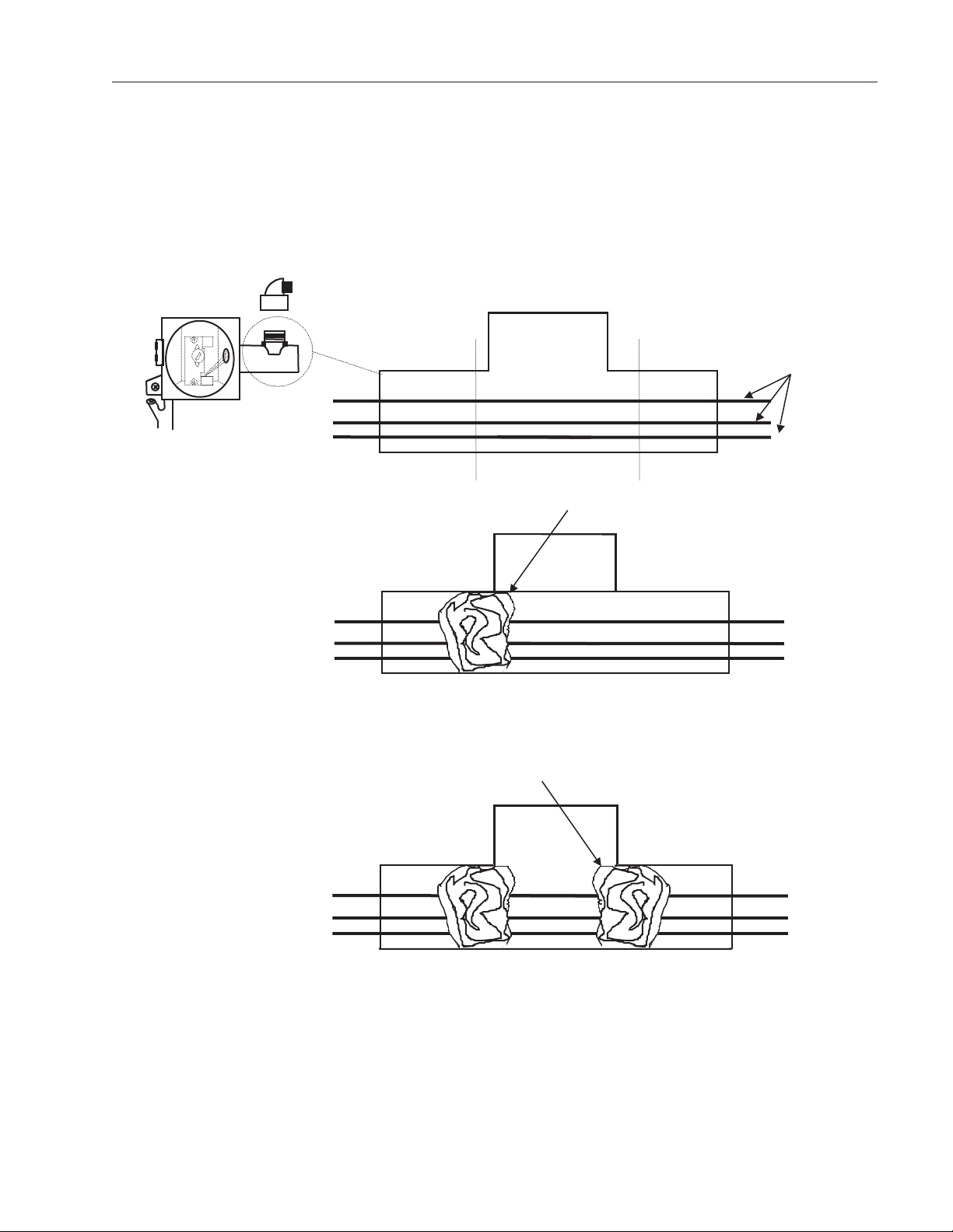
Sealing Killark Box Conduit to Help Protect Against Explosions ..........................................................................6
Operation......................................................................................................................................................................9
Environmental Operating Conditions ....................................................................................................................9
Child Entrapment Warning ....................................................................................................................................9
Start-Up Procedure................................................................................................................................................9
Restart Procedure................................................................................................................................................10
Manual Defrost Procedure ..................................................................................................................................10
How to Save Energy ............................................................................................................................................11
Safety Tips ..........................................................................................................................................................11
Reversing the Front Door (Model 97-920-1) ......................................................................................................12
eneral Purpose Laboratory Units ............................................................................................................................13
Model 97-920-1....................................................................................................................................................13
Model 97-915-1....................................................................................................................................................14
Model 97-960-1....................................................................................................................................................15
Model 97-926-1....................................................................................................................................................16
Flammable Materials Storage Units ..........................................................................................................................17
Overview..............................................................................................................................................................17
Model 97-925-1....................................................................................................................................................18
Model 97-938-1 ....................................................................................................................................................19
Model 97-935-1....................................................................................................................................................20
Explosion-Proof Units ................................................................................................................................................21
Model 97-952-1....................................................................................................................................................21
Model 97-928-1....................................................................................................................................................22
Model 97-950-1....................................................................................................................................................23
Options ......................................................................................................................................................................24
Optional Dolly ......................................................................................................................................................24
Installation Instructions ................................................................................................................................24
Optional Buzzer Alarm ........................................................................................................................................25
Maintenance ..............................................................................................................................................................27
Be Advised ..........................................................................................................................................................27
Cleaning of Units ................................................................................................................................................27
Interior/Exterior and Door askets ..............................................................................................................27
Condenser ....................................................................................................................................................27
Troubleshooting ..........................................................................................................................................................28
Replacement Parts ....................................................................................................................................................29
Warranty ....................................................................................................................................................................31
2
Table of Contents

At Fisher Scientific, we invite you to think of us as your
laboratory partner. Meeting all the needs of todayʼs labo-
ratories, whether industrial, educational or government,
large or small, is our sole objective.
Our 3,000 employees and 1,200 suppliers build on a long
and proud tradition of quality performance to bring our
customers an unmatched line of more than 130,000 prod-
ucts—plus the highest level of customer service, expert
technical assistance, and fast, accurate delivery.
We are the largest distributor for most of the major manu-
facturers whom we represent. We also manufacture
nearly 25% of the items we sell. With Fisher Scientific,
our team is your team. Youʼll find our customer service
representatives the most experienced and highly trained
in the scientific industry, and they are quickly available to
you via our toll-free hotline: 1-800-438-4851. Theyʼll assist
you promptly, and in a error-free manner, by providing up-
to-the-minute information on products, pricing, specifica-
tions, delivery and return procedures. Theyʼll arrange to
have your order shipped from one of our many Customer
Service Centers or additional warehousing facilities locat-
ed coast-to-coast.
For toll-free technical assistance call: 1-800-438-4851.
A Fisher Scientific Account Representative will visit your
laboratory when your orders are too complex to resolve
over the telephone. Theyʼll listen carefully to your needs
and help you decide on the combination of products and
services that best fulfill your requirements. They can pro-
vide you with the details on quotations, technical informa-
tion, product availability and ordering.
THE FISHER SCIENTIFIC QUALITY STATEMENT:
“Every one of us at Fisher Scientific is committed to satis-
fying the needs of our customers by providing products
and services that meet or exceed their requirements and
expectations. As a company, we place top priority on
quality, and we foster this through a continuing process of
improvements, in which employee contributions play a
vital role.”
Introduction
3

Shipping Carton
This should be inspected upon delivery. When received,
carefully examine for any shipping damage before
unpacking. If damage is discovered, the delivering carrier
should both specify and sign for the damage on your copy
of the delivery receipt.
Open the carton carefully making certain that all parts are
accounted for before packaging materials are discarded.
After unpacking, if damage is found, promptly report it to
the carrier and request a damage inspection promptly.
IMPORTANT: Failure to request an inspection of damage
within a few days after receipt of shipment absolves the
carrier from any liability for damage. You must call for a
damage inspection promptly.
Location
Locate your unit in the most convenient place and near a
grounded electric outlet. If units are placed on a counter-
top, the front should be 3" or more back from the edge to
avoid accidental tipping of the unit.
If possible, locate your unit out of direct sunlight and away
from heat sources such as a radiator, stove or heat duct.
Electrical
With the exception of Explosion-Proof models, all units
must be connected to a grounded outlet matching the
nameplate and/or the information furnished in this manu-
al.
If you are not sure about the outlet, you should contact a
qualified electrician for assistance.
The unit should always be connected to its own individual
outlet.
Explosion- roof models do not come supplied with a
cord and plug. Units must be hard-wired by a quali-
fied electrician.
Installation
Caution
DO NOT REMOVE, under any circum-
stance, the grounding prongs from the
3-prong power cord supplied with all
units. No cord/plug is supplied with
Explosion- roof units. Contact a
qualified electrician to hard-wire
unit.
Caution
DO NOT USE electrical extension
cords that may result in voltage loss
and possible hazardous operation.
4

Be Advised
DANGER: RISK OF CHILD ENTRAPMENT. BEFORE
YOU THROW AWAY YOUR OLD REFRI ERATOR OR
FREEZER:
• TAKE OFF DOORS
• LEAVE THE SHELVES IN THE PLACE SO
THAT CHILDREN MAY NOT EASILY CLIMB
INSIDE.
DANGER: UNLESS UNIT IS SPECIFICALLY DESI NED
FOR COMBUSTIBLE OR FLAMMABLE ATMOSPHERES
DO NOT USE IN THE PRESENCE OF FLAMMABLE OR
COMBUSTIBLE MATERIALS OR EXPLOSIVE ASES.
DO NOT USE IN THE PRESENCE OF PRESSURIZED
OR SEALED CONTAINERS—FIRE OR EXPLOSION
MAY RESULT CAUSIN DEATH.
WARNING: DO NOT HEAT ANY SUBSTANCE ABOVE A
TEMPERATURE THAT WILL CAUSE IT TO EMIT TOXIC
FUMES—DEATH OR SEVERE INJURY MAY RESULT.
WARNING: BEFORE CONNECTIN THE FINAL
POWER SUPPLY, CHECK THE ELECTRICAL CHARAC-
TERISTICS OF THE UNIT NAMEPLATE TO SEE THAT
IT IS IN A REEMENT WITH THE POWER SUPPLIED.
IN ADDITION, POWER SHOULD BE WIRED TO THE
UNIT ACCORDIN TO THE ELECTRICAL SCHEMATIC
AND ALL APPLICABLE CODES. ONLY QUALIFIED
ELECTRICIANS SHOULD WORK ON THE ELECTRICAL
PORTION OF ANY UNIT INSTALLATION.
CAUTION: SOLUTIONS USED TO CLEAN COILS OR
NEUTRALIZE BACTERIA ROWTH MUST NOT BE
CORROSIVE TO METALS (ENAMEL-COATED STEEL)
AND MATERIALS USED IN THE MAINTENANCE OF
THIS EQUIPMENT— DAMA E CAN RESULT. USE A
SOFT CLOTH AND WARM WATER TO CLEAN.
5
INSTALLATION

How to Seal Killark®Box Conduit with Fiber and
Sealing Compound to Help rotect Against
Explosions (Explosion- roof Units Only):
The purpose of the procedure that follows is to build fiber
rope dams on the left and right hubs of the horizontal conduit.
The fiber rope damns will surround conduit wiring that is
housed inside the horizontal conduit.
When both the left and right fiber rope dams have been
pressed into place, sealing compound is poured between the
two and forms into an airtight plug.
All of this is done in order to prevent the very real threat of
gas entering the Killark box and a resulting serious explosion.
After the unit wires have been pulled through the horizontal
conduit the following procedure is required:
• Turn power off at the circuit breaker before proceed-
ing.
• Place a small amount of sealing compound gran-
ules, enclosed, into a clean mixing vessel. Add
small amounts of water while stirring until a thick
paste is formed, then carefully continue adding
smaller amounts of water until a thick gravy consis-
tency is achieved—NOT WATERY. Discard any
material that becomes too stiff to use. Never
attempt to restore workability by stirring in more
water.
• Locate silver Killark box, back/top-center of unit.
• Unscrew conduit domed-cover.
INSTALLATION
Unscrew and Remove Cover
Left Hub
ConduitDomed-Cover
ConduitOpening
HorizontalConduit
Right Hub
Figure 1: Sealing the Killark Box
6

• Insert fiber rope material down into horizontal conduit opening. Pressing down firmly, work the material into
the left hub and—most importantly—being sure the material COMPLETELY SURROUNDS THE WIRIN ,
from the top to the bottom, completely blocking this end of the horizontal conduit.
7
INSTALLATION
Left Hub Right Hub
Wiring
Figure 2: Horizontal Conduit, Cutaway
• Insert fiber rope material down into horizontal conduit opening. Pressing down firmly, work the material into
the right hub and—most importantly—being sure the material COMPLETELY SURROUNDS THE WIRIN ,
from the top to the bottom, completely blocking this end of the horizontal conduit.

8
INSTALLATION
• Pour sealing compound down in between the two fiber rope dams filling the remaining space. Pour slowly,
being careful not to trap air bubbles. Immediately wipe off any spilled sealing compound.
• Screw conduit domed-cover back onto conduit opening.
NOTE: INITIAL SETUP OF SEALIN COMPOUND WILL OCCUR IN APPROXIMATELY 30 MINUTES HOW-
EVER, THE SEALIN COMPOUND REQUIRES A MINIMUM OF 8 HOURS ABOVE 32ºF TO DEVELOP
SUFFICIENT STREN TH TO WITHSTAND EXPLOSIONS.

Environmental Operating Conditions
POLLUTION DE REE*: 2
INSTALLATION CATE ORY*: II
ALTITUDE: 2000 Meters MSL (Mean Sea Level)
HUMIDITY: 80% maximum, non-condensing
ELECTRICAL SUPPLY: 120VAC or 240VAC
VOLTA E TOLERANCE: ±10% of normal rated line
TEMPERATURE: 15ºC to 40ºC
PRODUCT USA E: This product is intended for use indoors only
Child Entrapment Warning
DAN ER: RISK OF CHILD ENTRAPMENT! Before you discard your old refrigerator or freezer:
• Remove door(s),
• Leave the shelves in place so that children may not easily climb inside.
9
Operation
Start-Up Procedure
Rotate the control knob clockwise to lower the tempera-
ture and counterclockwise raise it.
To check chamber temperature, place a dial thermometer
on a shelf in the center of the chamber. Initially, rotate the
temperature control knob to an arbitrary setting. Allow
approximately 2 hours for the temperature to initially stabi-
lize. Check the temperature and compare with the dial
setting.
Adjust dial further to reach the desired operating tempera-
ture. After chamber initially stabilizes, allow 1/2 to 1 hour
for the chamber temperature to stabilize after subsequent
temperature adjustments.
Because the markings on the dial do not indicate specific
temperatures, use them AS REFERENCE POINTS ONLY
for any future setting of the temperature.
If the room thermostat is turned below 60ºF at night, con-
sider setting the temperature control one step colder. It
should be left at this setting for the nighttime period;
return temperature control to original setting when the
room thermostat is returned to its normal setting.
*Refer to IEC 664-1

Restart Procedure
If unit is unplugged or turned off, allow 3 minutes before
restarting or plugging it back in.
Manual Defrost Procedure
(Where Applicable)
Do not use any sharp instrument, blade or scraper to
remove ice and frost on refrigerator surfaces because of
the very real danger of puncturing the cooling coil.
Do not use any electrical device to defrost the unit.
When frost accumulates to 1/4" or more, the operating
efficiency of the unit will be affected. Use the following
procedure to defrost manually:
• Rotate the temperature control knob to the OFF
setting.
• Disconnect the power cord from its outlet.
• Remove contents of unit. If practical, wrap con-
tents in paper and then in a heavy blanket to
maintain temperature of items, especially those
removed from a freezer. Wear protective gloves
to prevent frostbite when handling cold items.
• Open door and allow free circulation of ambient
air.
• To speed the process, place pan of warm water
inside the chamber.
• Wipe out the interior.
• Replace contents.
• Reconnect power cord to outlet and set temper-
ature control to desired operating temperature.
10
OERATION

How to Save Energy
• Be sure to follow location suggestions as men-
tioned in the previous INSTALLATION section.
• Wipe moisture from glassware or other materials
before placing them in a unit.
• Don't overcrowd the unit. Too many items can
increase electrical energy demand in order to
keep everything cool.
• Close the door as soon as possible in hot, humid
weather.
• Make certain that the door is closed tightly.
• As soon as frost has accumulated to 1/4”,
defrost.
• Keep containers covered, when possible, to
reduce moisture buildup.
• Set operating temperature no colder than neces-
sary for the items being refrigerated.
Safety Tips
• After a unit is in operation, do not touch the cold
surfaces, particularly when hands are damp.
Skin may adhere to the extremely cold surfaces.
• Never disconnect your unit by pulling on the
power cord. Always grip the plug securely and
pull straight out from the outlet.
• Do not use a power cord that shows cracks or
abrasions. Have a qualified electrician repair or
replace damaged cords immediately.
11
OERATION

Reversing the Front Door
(Model 97-920-1)
• Remove bolts and plugs using a screwdriver.
• Unscrew the bolts connecting the upper hinges to
the upper platform. Remove the upper platform by
first pulling it forward and then lifting it upward.
• Remove the door by unscrewing the bolts in the
upper hinges.
• Remove the buffer by unscrewing the bolts on both
of its sides.
• Break off the part behind the buffer through which
the lower hinges pass using a knife or your hands.
• Remove the lower hinge and mount it on the other
side tightening its bolts.
• Remove the hole-plugs of the door handle with a
knife.
• Fit the hole-plugs of the door handle to the other
side.
• Fit the buffer to its place.
• Mount the door to its place.
• Fit the upper hinges into their places. Do not tighten
the bolts, but leave them loose.
• Adjust the vertical and parallel position of the door
by eyesight then tighten the bolts of the upper
hinges.
• Fit the upper platform into its place.
• Fit the bolts connecting the upper hinges and the
upper platform, but do not tighten them.
• Adjust the upper platform until it is level then tighten
the bolts in operations.
• Fit the plugs of the upper platform.
12
OERATION

13
eneral-Purpose Laboratory Units
ledoMsnoisnemiDrebmahCrotaregirfeR
)mc(sehcniDxWxH
.loVlatoT
.tF.uC
snoisnemiDroiretxE
)mc(sehcniDxWxH
1-029-79"5.31x"5.02x"5.72
)mc43x25x07(
6.5"5.52x"57.32x"5.33
)mc56x06x58(
Model Electrical Characteristics
Volts/Hz, Watts, Amps
Refrig. Temp.
Range °C (°F)
Net Wt.
Lbs. (kg)
Ship Wt.
Lbs. (kg)
97-920-1 120/60, 160, 1.3 2° to 7°
(36° to 45°)
100 (46) 120 (55)
NOTE: Amps listed are at normal run mode, starting amps may be higher.
MODEL 97-920-1
Features:
• 5.6 cubic ft. undercounter refrigerator.
• Manual defrost.
• Adjustable hydraulic thermostat control.
• Three adjustable wire shelves.
• Key lock.
• UL listed.
97-920-1 NOTE: THESE UNITS ARE DESI NED FOR
FREE STANDIN INSTALLATION ONLY. THEY MAY BE
INSTALLED UNDER A COUNTER ONLY IF SUFFICIENT
SPACE FOR AIRFLOW IS PROVIDED. 1” ON THE SIDES,
TOP AND REAR ARE RECOMMENDED.

14
GENERAL- UR OSE LABORATORY UNITS
15” x 16” x 14”
(38 x 41 x 36 cm)
97-915-1
Model Refrigerator Chamber Dimensions
H x W x D inches (cm)
Freezer Chamber Dimensions
H x W x D inches (cm)
Exterior Dimensions
H x W x D inches (cm)
Total Vol.
Cu. Ft.
1.7
6” x 6” x 10”
(15 x 16 x 25 cm)
19” x 18.5” x 20”
(48 x 47 x 51 cm)
120/60, 96, 0.8
97-915-1
Model Electrical Characteristics
Volts/Hz, Watts, Amps
Refrig. Temp.
Range °C (°F)
Net Wt.
Lbs. (kg)
35 (16)
Ship Wt.
Lbs. (kg)
40 (18.2)
0° to 7°
(32° to 45°)
NOTE: Amps listed are at normal run mode, starting amps may be higher.
MODEL 97-915-1
Features:
• 1.7 cubic ft. bench top refrigerator with ice compartment.
• Single door.
• One removable shelf included.
• Manual defrost.
• UL listed.
97-915-1 NOTE: ALLOW THE FOLLOWIN CLEARANCE
TOP: 12”, BACK: 5”, SIDES: 1/2”

15
GENERAL- UR OSE LABORATORY UNITS
ledoMsnoisnemiDrebmahCrotaregirfeR
)mc(sehcniDxWxH
snoisnemiDrebmahCrezeerF
)mc(sehcniDxWxH
.loVlatoT
.tF.uC
snoisnemiDroiretxE
)mc(sehcniDxWxH
1-069-79"5.51x"81x"12
)mc93x64x35(
"11x"5.51x"6
)mc82x93x51(
6.5"5.52x"57.32x"5.33
)mc56x06x58(
Model Electrical Characteristics
Volts/Hz, Watts, Amps
Refrig. Temp.
Range °C (°F)
Net Wt.
Lbs. (kg)
Ship Wt.
Lbs. (kg)
97-960-1 120/60, 160, 1.3 2° to 7°
(36° to 45°)
Freezer Temp.
Range °C (°F)
-6° to 1°
(21° to 33°)
100 (46) 120 (55)
NOTE: Amps listed are at normal run mode, starting amps may be higher.
MODEL 97-960-1
Features:
• 5.6 cubic ft. undercounter refrigerator/freezer.
• Adjustable thermostatic control.
• Three wire shelves, three door shelves.
• ABS plastic interior with enameled steel exterior.
• Manual defrost.
• UL listed.
97-960-1 NOTE: THESE UNITS ARE DESI NED FOR
FREE STANDIN INSTALLATION ONLY. THEY MAY BE
INSTALLED UNDER A COUNTER ONLY IF SUFFICIENT
SPACE FOR AIRFLOW IS PROVIDED. 1” ON THE
SIDES, TOP AND REAR ARE RECOMMENDED.

16
GENERAL- UR OSE LABORATORY UNITS
97-926-1 28” x 18” x 15”
(71 x 46 x 38 cm)
33.5” x 21.5” x 25.5”
(85 x 55 x 65 cm)
5.0
Model Freezer Chamber Dimensions
H x W x D inches (cm)
Exterior Dimensions
H x W x D inches (cm)
Total Vol.
Cu. Ft.
Model Electrical Characteristics
Volts/Hz, Watts, Amps
Net Wt.
Lbs. (kg)
Ship Wt.
Lbs. (kg)
Freezer Temp.
Range °C (°F)
97-926-1 120/60, 132, 1.1 -20° to -15°
(-4° to 5°)
75 (34) 95 (43)
NOTE: Amps listed are at normal run mode, starting amps may be higher.
MODEL 97-926-1
Features:
• 5.0 cubic ft. undercounter freezer.
• Hydraulic thermostat.
• Two fixed shelves and three door shelves.
• Manual defrost.
• UL listed.

Overview
These Fisher units will prevent potentially destructive
explosions in any facility. They meet the standards estab-
lished by Underwritersʼ Laboratory, Inc., OSHA and
National Fire Protection Association for storage of haz-
ardous materials. They also are designed to comply with
National Fire Protection Association Standards No. 45
and 99, as well as, OSHA Article No. CFR 1910.308.
Fisher Flammable Materials Storage Refrigerators are
manufactured for safe, cold storage of volatile materials.
Flammable Materials Storage (FMS) Refrigerators will
prevent an explosion from occurring inside the unit.
These units have no internal electrical components that
could trigger an explosion of hazardous materials inside
the unit. They are NOT designed for use in Class I,
roups C and D environments. For these locations use a
Fisher Explosion-Proof Refrigerator. However, FMS units
are not suitable for use in Class I, roup C and D
environments.
These units are ideal for storing cyclopropane, ethyl ether,
ethylene, acetone, alcohol, benzene, butane, gasoline,
hexane, lacquer solvent vapors, naphtha, natural gas or
propane along with many other potentially hazardous
materials.
All cabinets have heavy-gauge steel construction with a
durable exterior finish of epoxy enamel. A well insulated
cabinet and tight sealing magnetic door prevent air leaks
along with helping to lower operating costs. The interior
is made of porcelain enameled steel or ABS plastic.
Fisher offers the largest selection of FMS units. All mod-
els are delivered with 3-wire line cord and molded plug.
17
Flammable Materials Storage Units

18
FLAMMABLE MATERIALS STORAGE UNITS
97-925-1 28” x 18” x 15”
(71 x 46 x 38 cm)
33.5” x 21.5” x 29.5”
(85 x 55 x 75 cm)
5.0
Model Freezer Chamber Dimensions
H x W x D inches (cm)
Exterior Dimensions
H x W x D inches (cm)
Total Vol.
Cu. Ft.
Model Electrical Characteristics
Volts/Hz, Watts, Amps
Net Wt.
Lbs. (kg)
Ship Wt.
Lbs. (kg)
Freezer Temp.
Range °C (°F)
97-925-1 120/60, 132, 1.1 -20° to -15°
(-4° to 5°)
85 (39) 110 (50)
NOTE: ALLOW FOR 4 INCHES OF ADDITIONAL SPACE
AT THE REAR OF FLAMMABLE MATERIAL STORA E
UNITS TO ACCOMMODATE THE THERMOSTAT HOUS-
IN .
NOTE: Amps listed are at normal run mode, starting amps may be higher.
MODEL 97-925-1
Features:
• 5.0 cubic ft. undercounter freezer.
• Hydraulic thermostat.
• Two fixed wire shelves, three door shelves.
• Aluminum evaporator coil.
• Manual defrost.
• UL listed.

19
FLAMMABLE MATERIALS STORAGE UNITS
ledoMsnoisnemiDrebmahCrotaregirfeR
)mc(sehcniDxWxH
.loVlatoT
.tF.uC
snoisnemiDroiretxE
)mc(sehcniDxWxH
1-839-79"5.31x"5.02x"5.72
)mc43x25x07(
6.5"5.92x"57.32x"5.33
)mc57x06x58(
Model Electrical Characteristics
Volts/Hz, Watts, Amps
Refrig. Temp.
Range °C (°F)
Net Wt.
Lbs. (kg)
Ship Wt.
Lbs. (kg)
97-938-1 120/60, 160, 1.3 2° to 7°
(36° to 45°)
100 (46) 120 (55)
NOTE: Amps listed are at normal run mode, starting amps may be higher.
NOTE: THIS UNIT IS DESI NED FOR FREE STAND-
IN , RECESSED OR UNDER THE COUNTER INSTAL-
LATION. IT IS SU ESTED THE USER HAVE EASY
ACCESS TO THE KEY LOCK.
NOTE: ALLOW FOR 4 INCHES OF ADDITIONAL SPACE
AT THE REAR OF FLAMMABLE MATERIAL STORA E
UNITS TO ACCOMMODATE THE THERMOSTAT HOUS-
IN .
MODEL 97-938-1
Features:
• 5.6 cubic ft. undercounter refrigerator.
• Hydraulic thermostat.
• Three adjustable wire shelves.
• Aluminum evaporator coil.
• Manual defrost.
• Key locking door.
• UL listed.

20
FLAMMABLE MATERIALS STORAGE UNITS
ledoMsnoisnemiDrebmahCrotaregirfeR
)mc(sehcniDxWxH
snoisnemiDrebmahCrezeerF
)mc(sehcniDxWxH
.loVlatoT
.tF.uC
snoisnemiDroiretxE
)mc(sehcniDxWxH
1-539-79"5.51x"81x"12
)mc93x64x35(
"11x"5.51x"6
)mc82x93x51(
6.5"52.92x"52.12x"5.33
)mc47x45x58(
Model Electrical Characteristics
Volts/Hz, Watts, Amps
Refrig. Temp.
Range °C (°F)
Net Wt.
Lbs. (kg)
Ship Wt.
Lbs. (kg)
97-935-1 120/60, 160, 1.3 2° to 7°
(36° to 44°)
Freezer Temp.
Range °C (°F)
-6° to 1°
(21° to 33°)
100 (46) 120 (55)
NOTE: Amps listed are at normal run mode, starting amps may be higher.
MODEL 97-935-1
Features:
• 5.6 cubic ft. undercounter refrigerator/freezer.
• Hydraulic thermostat.
• Two adjustable wire shelves.
• Manual defrost.
• UL listed.
97-935-1 NOTE: THESE UNITS ARE DESI NED FOR
FREE STANDIN INSTALLATION ONLY. THEY MAY BE
INSTALLED UNDER A COUNTER ONLY IF SUFFICIENT
SPACE FOR AIRFLOW IS PROVIDED. 1” ON THE
SIDES, TOP AND REAR ARE RECOMMENDED.
IN ADDITION, ALLOW FOR 4 INCHES OF ADDITIONAL
SPACE AT THE REAR OF FLAMMABLE MATERIAL
STORA E UNITS TO ACCOMMODATE THE THERMO-
STAT HOUSIN .
This manual suits for next models
9
Table of contents
Other Fisher Scientific Refrigerator manuals

Fisher Scientific
Fisher Scientific 17LREEFSA User manual

Fisher Scientific
Fisher Scientific 13-986-127G User manual

Fisher Scientific
Fisher Scientific Isotemp 153 Original instructions

Fisher Scientific
Fisher Scientific 13-986-450R Instruction Manual

Fisher Scientific
Fisher Scientific 17LREEFSA User manual

Fisher Scientific
Fisher Scientific 10ECEEFSA User manual

Fisher Scientific
Fisher Scientific Isotemp Series Programming manual

Fisher Scientific
Fisher Scientific Isotemp 13-986-153 User manual

Fisher Scientific
Fisher Scientific 13-986-120A User manual