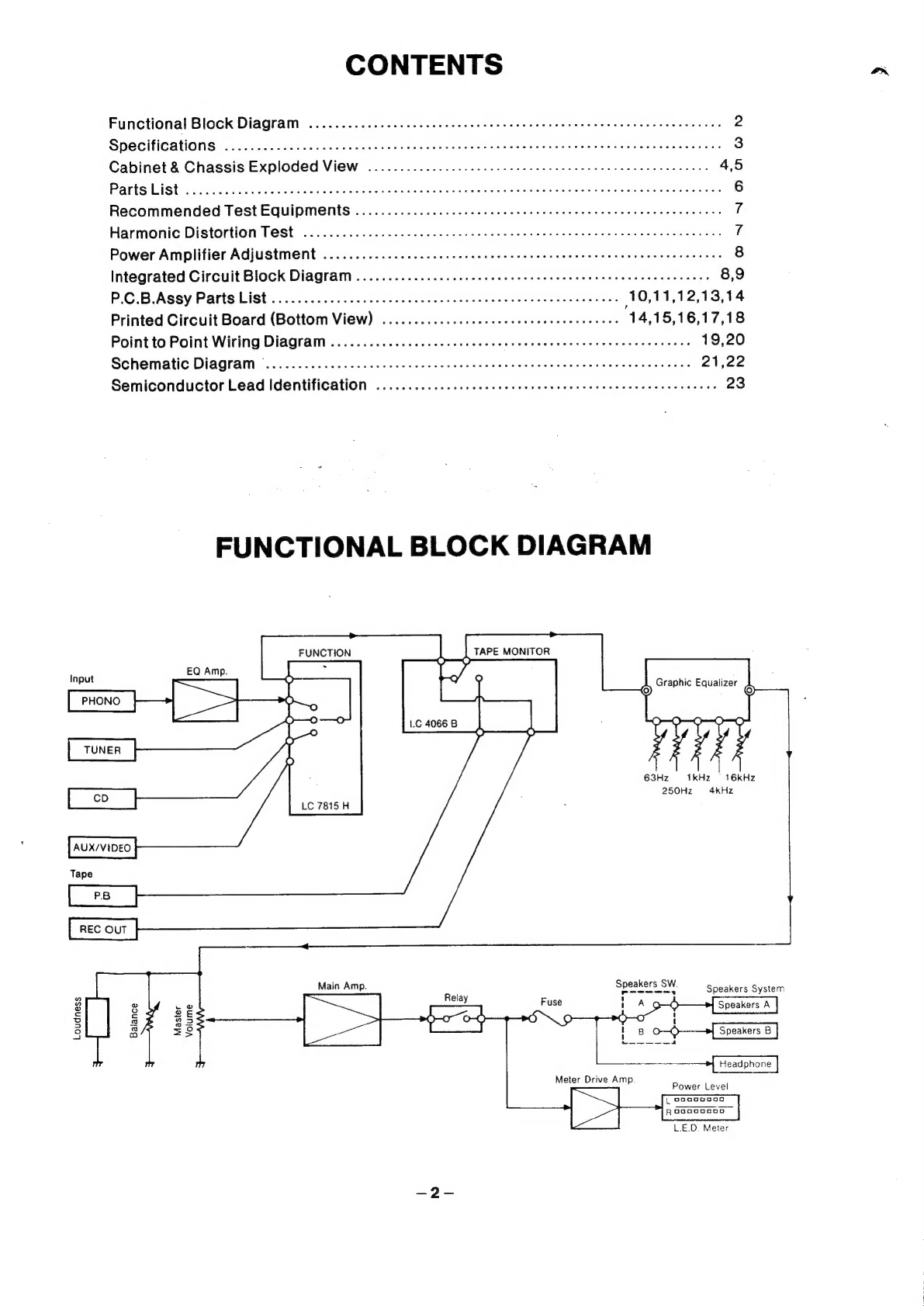
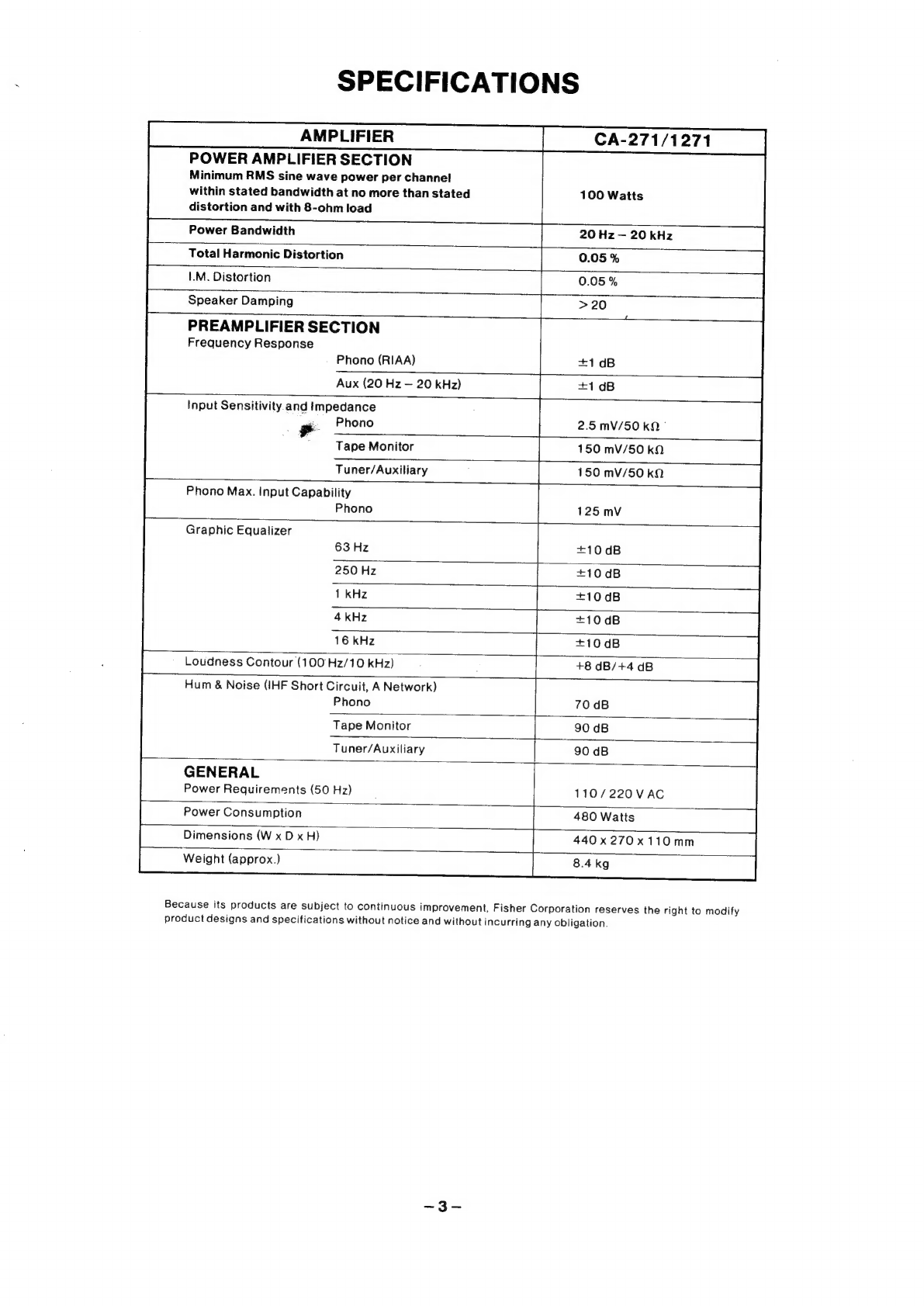
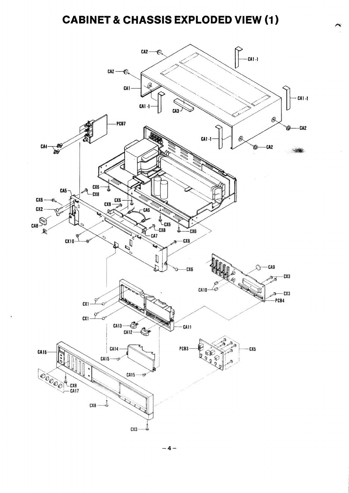
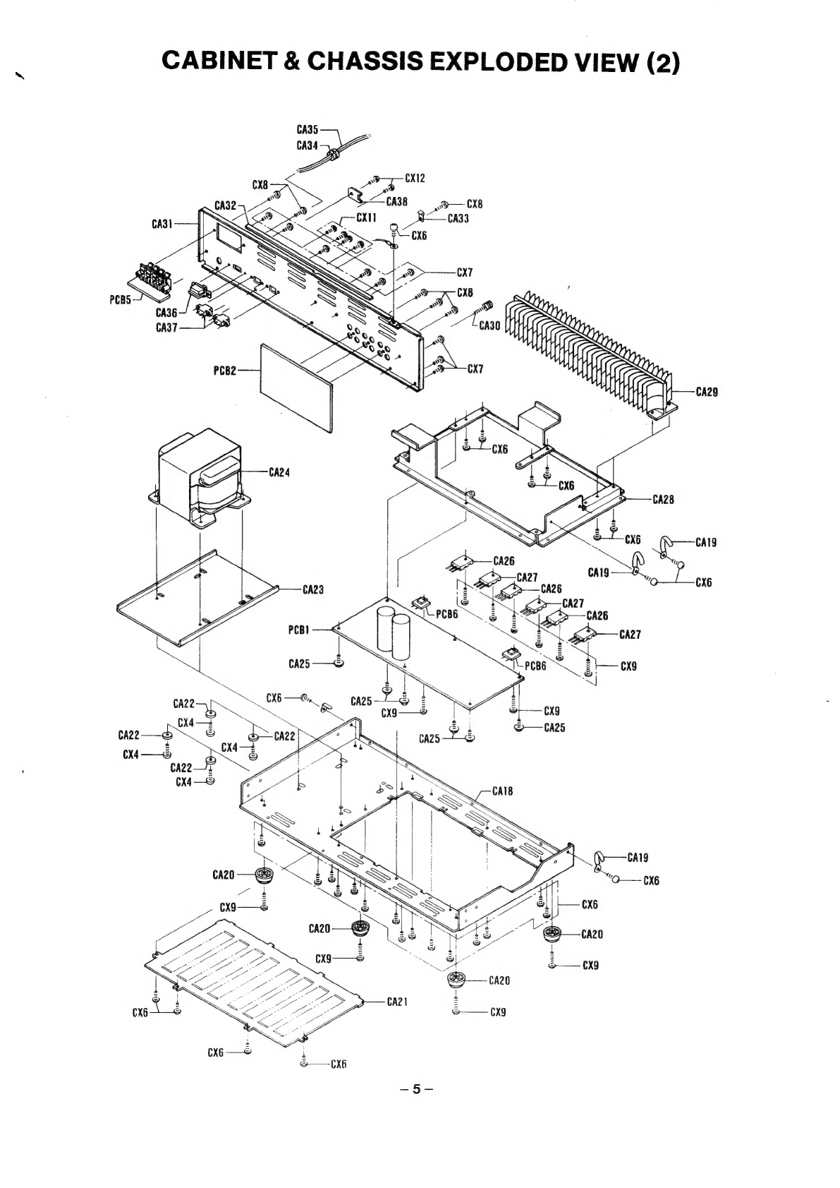
Fisher CA-271 User manual
Other Fisher Amplifier manuals

Fisher
Fisher X-100 User manual

Fisher
Fisher KX-200 Installation guide

Fisher
Fisher CA-857 User manual

Fisher
Fisher CA-520 User manual

Fisher
Fisher K-1000 Troubleshooting guide

Fisher
Fisher KX-200 Installation guide

Fisher
Fisher CA-874 User manual

Fisher
Fisher CA-9335 User manual

Fisher
Fisher Series 80-C User manual

Fisher
Fisher CA-2030 User manual