Fisher CA-890 User manual

wll
—
SERVICE
MANUAL
}
WITH
#
WIRELESS
Rt
REMOTE
CONTROL
cick
:
-890
‘Integrated
—
‘Stereo
Amplifier
(EUROPE)
132
301
40
NOTE:
This
model
is
supplied
with
the
Remote
Control
REM-890.
For
details,
refer
to
the
Remote
Contro!
REM-890
of
the
Service
Manual
(WM-17355).
WM-17154

CONTENTS
Functional
Block
Diagram
.........
0c
ccc
cece
cece
cece
ene
e
eee
eee
tent
neen
tn
teeeenaes
3
SPECIUICATIONS
seca
save
elles
enlhie
oY
sak
Soa
wih
andddoies
ad
peels
pins
dae
eee
eeeaaekadacees
4
CirGUlt
DESCFIPTION
crccieiseiacoudarsaseeaceelea
Bares
cieconn’s
uot Mow
belo
toda
ad
o
sible
Wieates
ele
ead
a
Saree
ANS
5
Explanation
of
Function
(TMP4270N)
........0....cc
cc
cece
cece
eee
eee
e
cc
eeeeeaneenans
6,7
Sub
CPU
TMP4270N
Port
Assignment
............
0.
ccc
cece
cece
cee
cece
eee
eeneteenenens
8
Explanation
of
Functions
(TMP47C400N)
.............
0c
ccc
c
cece
eect
e
te
vesveeaeeeunes
9
Main
CPU
Port
Designation
(TMP47C400N)
............
cece
cece
eee
ee
eee
e
eee
eeaeenans
10
Recommended
Test
Equipments
.............-.c
cece
cect
e
ec
ee
cece
enenes
Apis
team
wis
11
Harmonic
Distortion
TeSt
..........
0.
cc
ccc
ccc
cece
eee
eee
e
eee
eee
e
ence
een
ene
neeetneneees
11
Power
Amplifier
Adjustment
.............
cece
c
ccc
cece
cece
ete
ete
c
eee
teeeeeeereeeeeannes
12
Cabinet
&
Chassis
Exploded
View
(1)
............
00...
c
cece
cece
eee
eee
eee
eeeesueneesaeaee
13
Cabinet
&
Chassis
Exploded
View
(2)
...........
cc
ccc
cece
ccc
c
cece
n
sense
eeeeueneeeneas
14
Cabinet
&
Chassis
Exploded
View
(3)
.........
0.0.0.
ccc
ccc
ce
eee
cen
este
ee
venusneeanenes
15
Cabinet
&
Chassis
Parts
List
.........
0...
ccc
cece
cece
ence
eee
nett
ee
een
e
ene
eeanenanes
16
Printed
Circuit
Board
Parts
List
...........
0.
cece
cece
cece
eee
e
teen
eee
eneeeeens
17
~
24
Printed
Circuit
Board
(Bottom
View)
..............
0c
ccc
cece
ccc
cence
cent
cere
nn
nes
25
~
34
Point
to
Point
Wiring
Diagram
............
ccc
ec
cee cee
ene
e
nee
e
eee
e
eee
n
eset
neta
35,36
Semiconductor
Lead
Identification.
..........
0...
cece
cece
eee
nee
cnet
nee
ee
eee
ees
37,38
Integrated
Circuit
Block
Diagram
...........
0.00.
ccc
cece
cece
tenet
een
eeeeeneeeee
38,39
NOTE:
Schematic
Diagram
is
separately
attached
to
this
manual.

FUNCTIONAL
BLOCK
DIAGRAM
Ajddng
Jamoq
Aq-puejg
“SUB
|
JaMOd
qns
OV
YoUMs
JaMod
*‘SUBL]
JAMOd
uleyy
—
Aejay
OP
aso/no
JaMOod
¥
dZlezvi
30199]
01d
Joyeaipu]
SWINjOA-O}
sosuas
jBUWeUL
D.00t
YOM
|OuJUOD
oNJeWeled
Aejeu
ones
ee
eae
ZHOO9
ZHSZ
anno
eoeel
4sayeeds
pueg
|
pueg
O—o
uBIH
mo7
JOsUOD
JazyeNby
‘dwy
49M0
Mi
¢
OlJOWeEIed
OP
LOVE
O14219W
{9A87
JOMOd
19]3W
8097
JaMod
“GNI
3
YDYIMS
29y
O1yoUAS/a}NW/sseupnoy
NOOPOLPdWL
JajNdwog
sl;
UleW
dp)
awnjo,
|
dZZ1601L
9]
AWNIOA
213199/9
sassrov1
Oo)
duy
ad
YOUMS
493
yBIH
Yo}IMS
Jay
4
oluosqns
josjuoD
Wa}shS
|
« _
|
ely
lod7
Oy
dwy
aid
JOuJUOD
BjoWaY
3SNWd
|
HOAd
=NMOQANNTOA
aTevVLNENl
Osid
LOVdWOO
ONINAL
Wa
WY
YHSNNL
dn
SWNIOA
ONILAW
AdV1
OACIA/XNY
Y5MOd
9z0190d7
Ol
seyiwsuedy
Jo1U0D
aJoWSaY
JOYULNOS
SLOWSY
SWALSAS
ONIGHOD3Y
ONHONAS
awnjon
aourleg
[van]
NOILONN4
OILYWOLNY
zodey
-O
d/d
J
>
©
0/4
LNO
93uY
YOUMS
zode)
YOA
tede,
a/d
ont!
XNV
YOA
AL
ONOHd
dozzcw
Oo]
duy
‘OF

SPECIFICATIONS
POWER
AMPLIFIER
SECTION
Minimum
RMS
sine
wave
power
per
channel
within
stated
bandwidth
at
no
more
than
stated
150
Watts
distortion
and
with
8-ohm
load
Power
Bandwidth
20
Hz
—
20
kHz
Total
Harmonic
Distortion
0.02
%
I.M.
Distortion
0.02
%
Speaker
Damping
>20
PREAMPLIFIER
SECTION
Frequency
Response
Phono
(RIAA)
+1
dB
Aux
(20
Hz
—
20
kHz)
+1dB
Input
Sensitivity
and
Impedance
Phono
2.5
mV/50
kQ.
VCR
Tape
Monitor
1,2
150
mV/50
kQ
Tuner/TV/CD/Aux
art
150
mV/50
kQ.
i.
Phono
Max.
Input
Capability
140
mV
Parametric
Equalizer
25
Hz
—
800Hz
+12dB
600
Hz
-
20kHz
+12dB
High
Filter
(Above
10
kHz)
—6dB/Oct.
Subsonic
Filter
(Below
10
Hz)
—12dB/Oct.
Loudness
Contour
(100
Hz/10
kHz)
+8
dB/
+4
dB
Hum
&
Noise
({HF
Short
Circuit,
A
Network)
[
Phono
80
dB
VCR/Tape
Monitor
1,2
95
dB
Tuner/TV/CD/Aux
95
dB
GENERAL
Power
Requirements
(50Hz)
110/220V
AC
Power
Consumption
700
Watts
AC
Outlets
2
Dimensions
(W
x
H
xD)
440
x
140
x
320
mm
Weight
(approx.)
11.8kg
Because
its
products
are
subject
to
continuous
improvement,
Fisher
Corporation
reserves
the
right
to
modify
product
designs
and
specifications
without
notice
and
without
incurring
any
obligation.

CIRCUT
DESCRIPTION
The
CA-890
has
the
following
features:
Full
Remote
Control/Auto
Function
Selection
_
AV-Compatible
High
Output
Power
Amplifier
(150W
x
2)
Built-in
Parametric
Equalizer
Multi-Protection
circuit
aos
1.
Full
Remote
Control/Auto
Function
Selection
The
infrared
remote
control
can
be
used
for
control
of
46
different
audio
system
functions
—
that
is,
practically
ail
functions.
Also,
auto
function
selection
and
synchronized
recording
are
possible
not
only
with
manual
operation
but
also
by
remote
control.
In
order
to
make
this
possible,
two
types
of
microprocessors
have
been
developed;
a
main
microprocessor
{4k-byte
ROM
capacity)
and
a
sub
microprocessor
(1k-byte).
The
main
microprocessor
is
built
into
the
amplifier,
and
sub
microprocessor
are
mounted
in
the
components
(tuner,
CD
player,
turntable,
cassette
deck).
These
microprocessors
exchange
data
mutually.
As
shown
below,
the
main
and
sub
microprocessors
are
connected
by
two-way
data
buses.
When
the
remote
contro!
is
used
and
auto
function
selection
is
performed,
the
function
indicator
flashes
(CD
player,
cassette
deck,
turntable).
Directly
before
access
is
completed
and
sound
is
output,
the
indicator
stops
flashing
and
remains
lit,
thus
allowing
safe
remote
control
even
at
a
distance.
DaTa
CLock
ReaDY
—
REQuest
GND.
Main
Sub
Microprocessor
Microprocessor
Data
is
transferred
in
serial
by
clock
synchronization,
and
the
READY
and
REQ
lines
are
used
for
control
of
interruption
in
order
to
assure
proper
operation.
2.
AV-Compatible
The
CA-890
is
equipped
with
TV
and
VCR
input
jacks
and
output
jacks
for
VCR
recording,
making
it
possible
to
use
the
CA-890
to
construct
a
full
AV
system.
There
are
also
DIN
terminals
for
extracting
information
on
the
status
of
the
audio
components,
which
when
used
permit
the
display
of
the
status
on
the
TV
screen.
3.
High
Output
Power
Amplifier
(1
50W
x
2)
A
triple
cascode
is
used
in
the
first
stage,
preventing
deterioration
of
the
THD
due
to
changes
in
the
signal
source
impedance,
that
is
in
the
volume
position.
Also,
as
each
of
the
three
cascodes
uses
a
1-chip
dual
transistor,
the
structure
is
electrically
and
thermal
well
balanced
and
stable.
For
the
final
stage,
a
large
PC200W
epitaxial
planar
transistor
is
operated
by
single
push,
obtaining
150W
at
20
~
20kHz
with
THD
of
below
0.02%.
Current
mirror
chip
OUT
Vi
converter
chip
Differential
amp
chip
+IN
—IN
Triple
cascode
4.
Parametric
Equalizer
The
CA-890
uses
the
same
highly
successful
parametric
equalizer
as
was
used
on
the
CA-276.
Any
two
frequencies
can
be
varied
independently
by
+12
dB.
The
frequency
range
is
from
20
~
800Hz
in
the
low
band,
and
from
600
~
20kHz
for
the
high
band.
Q
is
fixed
at
1.2.
5.
Protection
Circuits
The
CA-890
is
equipped
with
three
different
protection
circuits,
protecting
against
a
variety
of
problems.
®
DC
detection
(speaker
protection)
The
speaker
jacks
are
cut
off
at
the
relay
if
a
DC
voltage
of
3V
or
greater
is
generated.
@
Temperature
dectection
(amplifier
protection)
If
the
temperature
of
the
radiator
reaches
120°C
(equivalent
to
power
transistor
junction
temperature
of
150°C),
this
is
detected
by
a
posistor
and
the
speaker
jacks
are
cut
off
at
the
relay.
@
Load/short-circuit
protection
(amplifier
protection)
If
the
speaker
jacks
are
short-circuited
or
they
are
connected
to
a
low
impedance
load,
the
ASO
limiter
is
activated
and
the
power
transistor
is
protected.
If
certain
conditions
in
the
relation
of
the
power
transistor
current
and
load
impedance
are
fulfilled,
this
ASO
limiter
interrupts
the
input
signals
using
the
muting
circuit.
+Va
+e
Volt
Amp.
7—a-
OUT

EXPLANATION
OF
FUNCTION
(TMP4270N)
System
Outline
of
TMP4270N
This
program
operates
an
audio
full
remote
control
system
SUB
CPU.
The
system
configuration
is
as
follows.
SUB1
|
es
TUNER
<“—
|
TMP4270N
C’
Main
Unit
aoe
DECK
“—|
1MP4270N
eae:
leses|
Main
Unit
Main
CPU
TMP47C400
ee
anes
CD
PLAYER
TMP4270N
Pees,
Sa
Main
Unit
RECORD
<>
Rae
C)
/)\\
PLAYER
[=
|S
Mainunit
Main
Micro-processor
Control...
Outputs
serial
data
received
from
the
main
micro-processor
to
the
appropriate
mode
key.
Main
Unit
Key
Control...
Transmits
the
main
unit
function
key
and
Mute
inputs
to
the
main
micro-processor.
Transmission/Reception
The
sub
micro-processor
carries
out
8
bit
serial
data
reception
and
transmission
with
the
main
micro-processor.
!t
takes
data
from
the
main
micro-processor
and
emits
a
100ms-wide
pulse
to
the
corresponding
port.
When
the
tact
switches
installed
connected
to
each
port
are
depressed,
the
corresponding
data
are
transmitted
to
the
main
micro-processor.
The
following
ports
are
used
for
data
transmission
and
reception.
DATA
|
CLOCK
READY
|
REQUEST
|
Assignment
Transmission
from
Main
to
Sub
Micro-processors.
1.
Main
micro-processor
emits
a
REQ
signal,
and
waits
approximately
3ms
for
sub
micro-processor
to
receive
REQ
signal.
Sub
micro-processor
enters
data
standby
mode
when
REQ
signal
is
active.
Data
and
clock
signals
are
transmitted
from
the
main
micro-processor.
The
Sub
micro-processor
matches
the
clock
signal
and
reads
the
data.
:
Main
micro-processor
clears
the
REQ
and
moves
on
to
the
next
assignment.
Sub
micro-processor
checks
data
_
received
after
°
acknowledging
the
REQ
CLEAR
and
emits
100ms-wide
pulses
to
the
port
corresponding
to
the
data
code.
If
the
data
is
invalid
or
incomplete,
the
sub
micro-
processor
moves
on
to
the
next
assignment
without
doing
anything.
Checks
only
signals
received
from
the
main
micro-
processor
during
generation
of
the
100ms-wide
pulses.
In
the
event
that
valid
data
is
once
again
received
during
pulse
generation,
the
sub
micro-processor
shuts
the
pulse
off
for
a
30ms
period
and
emits
100ms-wide
pulses
corresponding
to
the
new
data
code.
Reception
check
at
this
time
also.
Transmission
from
Sub
to
Main
Micro-processors.
(DECK,
PLAYER,
etc.,
switches
depressed,
or
MUTE
at
low)
Sub
micro-processor
emits
a
REQ
signal
and
waits
2ms
for
the
unit
to
enter
the
READY
mode;
if
the
unit
does
not
enter
the
READY
mode
within
the
designated
time
period,
the
sub
micro-processor
clears
the
REQ
and
proceeds
to
the
next
assignment.
When
the
Main
micro-processor
detects
the
REQ
signai,
it
emits
a
READY
signal
within
2ms
and
enters
data
standby
mode.
If
after
the
sub
micro-processor
has
detected
a
READY
signal
it
does
not
detect
data
within
a
certain
period
of
time
(designated
differently
for
each
mode),
it
transmits
data
with
the
clock
signal
off.
After
this,
it
transmits
both
data
and
clock
signals,
waits
for
the
READY
signal
to
go
off
once
data
transmission
has
been
completed,
and
clears
REQ.
If
the
main
micro-processor
picks
up
the
data,
a
READY
signal
is
cleared.
Main
micro-processor
checks
the
data
and
switches
the
corresponding
function,
transmitting
a
code
to
the
sub
micro-processor
if
necesary.
1.

Transmission
and
Reception
Timing
1.
Transmission
from
Main
to
Sub
Micro-processors
2.
There
is
no
transmission
during
reception
from
the
main
micro-processor
or
during
output
of
received
data
to
ports.
3. In
the
event
that
new
data
is
received
from
the
main
micro-processor
during
output
of
received
data
to
ports,
the
Main
new
data
is
processed
by
shutting
off
port
output
for
30ms.
REQ.
Tuner
Key
ON
AK
[
|
DATA
=
OFF
:
i
!
I
!
1
|
|
I !
CLOCK
LULL
LA
B
Key
ON
OFF
i
I
(SUB
picks
up
data
at
signa!
low)
!
I
!
\
'aAKey!
'BkKey,
Input
count
input
count
2.
Transmission
from
Sub
to
Main
Micro-processors
|
!
|
A
Key
B
Key
Transmission
Transmission
Sup
®
Input
countis
30ms.
REQ.
app.
800ms
1.
FM/MW
key
functions
even
during
other
key
inputs.
2.
!f
two
or
more
keys
are
pressed
at
the
same
time,
the
port
DATA
with
the
smaller
port
number
takes
precedence.
one
Key
CLOCK
Key
input
is
received
at
decks
1
and
2
separately.
Z
The
timing
of
two
different
key
inputs
is
the
same
for
the
Tuner.
However,
this
is
not
the
case
for
the
REC-
PLAY
Tere
mode.
BEADY
3.
STOP
KEY
input
is
transmitted
if
2
or
more
different
keys
are
pressed
at
the
same
time
(excluding
REC-PLAY).
<>
4.
Only
the
REC
key
input
is
not
transmitted.
within
2ms
CD
Player
Key
Akey
ON
eae
OFF
j
(SUB
DATA)
!
I
TUNER
|
l
!
a
@
Transmission
sub-
B
Key
al
ied
gy
DECK
!
mode
is
determined
'
y
|
I
by
the
data
signal.
|
A
key
|
i
Data
signals
already
1
count
CD
PLAYER
=]
|
at
low
are
transmitted
-—
directly.
#
PLAYER
|
A
Key
Be
Transmission
®@
No
acknowledgement
if
all
key
inputs
are
not
turned
off.
Sub
Micro-processor
Transception
and
Key
Read
1.
If
two
or
more
keys
are
pressed
at
the
same
time,
the
port
Transception
1.
Key
inputs
are
not
acknowledged
during
main
micro-
processor
transception.
Key
inputs
are
also
not
acknowledged
during
output
of
received
data
to
ports
(i.
e.,
during
emission
of
100ms-
or
2.
30ms-wide
pulses).
3.
with
the
smaller
port
number
takes
precedence.
Eee
Player
Key
The
timing
of
two
different
key
inputs
is
the
same
for
the
CD
Player.
The
STOP
KEY
functions
even
during
other
key
input.
lf
two
or
more
keys
are
pressed
at
the
same
time,
the
port
with
the
smaller
port
number
takes
precedence.

SUB CPU
TMP
4270N
ASSIGNMENT
COMMON
DaTa
DaTa
DaTa
DaTa
DaTa
CLockK
CLock CLock
CLock
CLock
ReaDY
ReaDY
ReaDY
ReaDY ReaDY
REQuest
REQuest
REQuest
REQuest
RE
Quest
ee
=
STOP
STOP
1
STOP/PAUSE
Pt
=
START
FF
1
START
=
CUE
UP/DOWN
FR
1
-
i
/
PAUSE
1
7
P2o
MUTE
IN
MUTEIN
.
MUTE
IN
MUTE
IN
P21
DO04
Low
High High
P22
DO6
Low
High
Low
P30
REC
1
P31
PLAY
F
1
P32
PLAY
R
1
P33
DECK
1
P4o
STOP
2
P4;
FF
2
P42
FR2
P43
PAUSE
2
con
ies
———E
24
P50
REC
2
25
P51
PLAY
F2
PROGRAM
26
P52
PLAY
R2
FF
(Continuous)
27
P53
_
DECK
2
FB
(Continuous)
MUTE
ON
1
(H)
MUTE
IN
—
DC
MUTE
OFF
0
(L)
Nothing
MUTE
OFF
MUTE
OFF
MUTE
OFF

EXPLANATION
OF
FUNCTION
(TMP47C400N)
System
Outline
of
TMP47C400
This
program
operates
an
audio
full
remote
control
system
MAIN
GPU.
The
system
configuration
is
as
follows.
TUNER
TMP4270N
Remote
Control
Device
[ee
)
I]
wainccpu
DECK
TMP4270N
TMP47C400
vA
a»
=
Laeeay
emo
emo
TMP4270N
Amplifier
Keys
System
Configuration
Remote
Contro
Device
Control
...
The
remote
contro
device
uses
infrared
rays
to
signal
commands
that
are
picked
up
by
the
main
unit
and
displayed
on
the
CRT.
Main
Unit
Key
Control...
Carries
out
control
via
the
main
unit
function
keys
and
Mute
(key
inputs),
transmitting
the
contents
to
the
CRT.
Individual
Component
Key
Control
...
The
TMP4270N
SUB
CPUs
installed
on
each
component
provide
serial
transmission,
control,
and
transmission
of
contents
to
the
CRT.
The
Auto-function
Function...
With
this
function,
all
Tuner
key
operation,
Phono
and
CD
Start,
and
Deck
Play
can
be
initiated
from
the
remote
contro!
device;
also,
the
Function
switch
can
be
changed
and
a
PLAY
signal
can
be
output
to
the
designated
component
and
a
STOP
signal
to
all
other
components
upon
serial
reception
from
one
of
the
SUB
CPUs.
:
Synchro
RECORD
Function...
Using
either
the
remote
control
device
or
the
deck
main
unit
to
put
deck
1
on
REC-PLAY
with
the
Synchro
switch
in
the
ON
position
automatically
puts
the
unit
in
the
REC-
PAUSE
mode.
If
the
CD
or
phonograph
record
is
then
played,
a
PAUSE
command
is
output
to
deck
1
and
the
unit
enters
the
record
mode
whenever
the
MUTE
signal
is
low.

MAIN
CPU
PORT
DESIGNATIONS
(TMP47C400N)
TMP47C400N
Vpp
Electrical
Volume
Analog
Switch
Function
Data
Clock
Clock
Sub-seriaj
Strobe
Data
Input
Sub-serial
MUTE
Data
Output
Sub-serial
Requesi
Sub-serial
REP
Output
Remote
Control
Signal
Input
Ready
Output
Sub-serial
VCR
MUTE
Output
POWER
Output
Strobe
CRT
Serial
Output
Matrix
Output
Clock
CRT
Serial
Output
Data
CRT
Serial
Output
—10-

RECOMMENDED
TEST
EQUIPMENTS
The
following
test
equipments
are
recommended
to
completely
test
and
align
the
Amplifier:
e
Line
Voltage
Isolation
Transformer
e
AC
DC
Multimeter
e
Accurately
Calibrated
AC
Voltmeter
e
Oscilloscope
(Flat
to
100
kHz
Minimum)
e
Low-Distortion
Audio
Sine-Wave
Generator
e
Harmonic
Distortion
Analyzer
e
Two
(2)
Load
Resistors
8-ohms,
250
Watts
(Minimum
Rating)
HARMONIC
DISTORTION
TEST
CAUTION:
Limit
the
following
tests
to
no
more
than
ten
minutes
each.
Use
8-ohm
resistors,
with
a
minimum
power
rating
of
250
watts
when
connecting
a
load
across
the
SPEAKERS
terminal.
CONTROL
SETTINGS:
Unplug
the
AC
power
cord
and
set
the
front
panel
controls
as
follows:
e
POWER
switch
to
the
OFF
position.
e
SPEAKERS
switch
to
the
OFF
position.
e
LOUDNESS
CONTOUR
switch
to
the
OFF
position.
e
PARAMETRIC
EQ.
switch
to
the
DEFEAT
position.
e
METER RANGE
switch
to
the
200W
position.
e
TAPE
MONITOR
switch
to
the
SOURCE
position.
HIGH
FILTER
switch
to
the
OFF
position.
SUBSONIC
FILTER
switch
to
the
OFF
position.
MODE
switch
to
the
STEREO
position.
BALANCE
control
to
the
center
position.
FUNCTION
switch
to
the
AUX
position.
VOLUME
DOWN
button
to
the
MINIMUM
position.
LEFT
CHANNEL
DRIVEN
ONE
CHANNEL
DRIVEN:
1)
Connect
a
low
distortion
audio
generator
to
LEFT
AUX
IN
jack.
Set
generator
frequency
to
1
kHz and
output
to
minimum.
2)
Connect
an
8-ohm
load
resistor
between
SPEAK-
ERS
SYSTEM-A
LEFT
and
COM
terminals.
Connect
a
Harmonic
Distortion
Analyzer
and
an
AC
VTVM
in
parallel
across
the
8-ohm
load.
83)
Connect
the
AC
power
cord
and
set
SPEAKERS
switch
to
ON
position.
Set
the
volume
level
to
a
MAX
level
by
Pressing
the
VOLUME
UP
button.
4)
Increase
generator
output
for
150
Watts
RMS
(34.6
volts
across
the
8-ohm
load).
Harmonic
Distortion
Analyzer
should
measure
0.02
%
distortion
or
less.
5)
Repeat
steps
1
through
4
for
RIGHT
CHANNEL.
BOTH
CHANNELS
DRIVEN
Connect
8-ohm
load
resistors
across
LEFT
and
RIGHT
SPEAKERS
SYSTEM-A
terminals.
Adjust
generator
output
and
“VOLUME”
control
for
150
watts
at
Left
and
Right
Channels
(34.6
volts
across
the
8-ohm
loads).
Harmonic
Distortion
Analyzer
should
measure
0.02
%
distortion
or
less
at
each
channel.
CAUTION:
This
precision
high-fidelity
instrument
should
be
serviced
only
by
qualified
personnel,
trained
in
the
repair
of
transistor
equipment
and
printed
circuitry.
—11-

POWER
AMPLIFIER
ADJUSTMENT
BEFORE
ADJUSTMENT
Unplug
the
AC
power
cord
and
set
the
front
panel
controls
as
follows:
e
Power
switch
to
the
OFF
position.
e
Setthe
SPEAKERS
switch
to
the
OFF
position.
e
Setthe
volume
level
to
a
minimum
level!
by
Pressing
the
VOLUME
DOWN
button.
e
IDLING
CURRENT
ADJUSTMENT
VR501/VR502
(on
the
Main
Amplifier
P.C.Borad)
setting
to
me-
chanical
center
position.
e
Connect
the
AC
power
cord
and
Power
switch
to
the
ON
position.
IDLING
CURRENT
ADJUSTMENT
This
adjustment
is
very
sensitive
to
changes
in
ambient
temperature.
Allow
set
to
operate
for
5
mi-
nutes
before
attempting
this
adjustment.
LEFT
CHANNEL
AMPLIFIER
1)
Connect
the
DC
Voltmeter
between
Pins
T501
and
T502
on
the
Main
Amplifier
P.C.Board.
2)
Adjust
the
VR501
for
an
indication
of
15mV
(1OmV
~
35mV)
on
the
DC
Voltmeter.
RIGHT
CHANNEL
AMPLIFIER
1)
Connect
the
DC
Voltmeter
between
Pins
T503
and
T504
on
the
Main
Amplifier
P.C.Board.
2)
Adjust
the
VR502
for
an
indication
of
15mV
(10mV
~
35mV)
on
the
DC
Voltmeter.
AMPLIFIER
P.C.BOARD
LAYOUT
ALIGNMENT
POINTS
(TOP
VIEW)
re
ef
VR501
VR502
T502
Main
Amplifier
P.C.Board
-12-

CABINET
&
CHASSIS
EXPLODED
VIEW
(1)

CABINET
&
CHASSIS
EXPLODED
VIEW
(2)
ie
10
4
KVR
=,
ZX
.
—14-

CABINET
&
CHASSIS
EXPLODED
VIEW
(3)
—15-

Ref.
No.
=~
OON
DOS
WM
0
Part
No.
CABINET
&
CHASSIS
PARTS
LIST
Description
PACKING
PARTS
LIST
3-9415-10300
131
-6-1169-17903
131
-6-3009-35980
131
-6-3009-35990
131-6-3069-16350
131
-6-4559-11200
131
-6-9459-00300
141-6-2519-22290
Bag
Polyethylene
Box
Corrugate-Exp.
Pad
Pad
Patching
Sheet
Serial
No.
Sheet
Rubber
Band
Sheet
Polyethylene
ACCESSORIES
PARTS
LIST
4-1929-20234
131-6-2719-10401
142-6-4119-32892
REM-890
(EUR)
Bag
Fan
Explanatory
Booklet
CABINET
&
CHASSIS
PARTS
LIST
4-2379-21520
131
-6-4559-11200
131-0-1016-45500
p—
181-2-1203-65100
r—
131-2-1203-65200
7—
131
-2-1203-65500
——
131
-2-3608-16600
131-2-1205-29400
131-2-1410-32700
131-2-1410-34104
131-2-1801-13300
131
-2-2306-10700
131-2-3614-22200
131
-2-4208-49800
131
-2-6113-51200
131-0-1007-00600
|__-—
131-2-6113-52600
11
12
13
——
131
-2-6308-24601
131-2-6113-52700
131
-2-6308-24301
131
-0-1001-64200
|
__;—131-2-1601-90400
14
15
16
17
18
19
20
21
22
23
'—
131-2-1601-96200
131-2-1601-69600
131-2-1601-71000
131-2-1601-71001
131-2-1601-85202
131-2-1601
-95900
131-2-1601
-96100
131
-2-1601
-96300
131
-2-1601-96400
131
-2-1601-96600
131-2-1105-32000
131-2-3202-15600
131
-2-3202-15700
131
-2-3301-32000
131-2-3305-36200
131
-2-3306-40502
131-2-3605-10700
131-2-3701-30700
131-2-4201-17800
131-2-4208-49400
131-2-5101
-24600
131-2-5205-15300
131
-2-6103-25200
131-2-6103-25300
Terminal
Lug
Serial
No.
Sheet
Panel
Decorate
Assy
Panel
Control
A
Panel
Control
B
Panel
Control
Filter
Decorate
Plate
Dial
Cover
Cover
Heat
Sink
Leg
Metal
Mount
Ground
Mount
P.C.B.
Spacer
Shelter
Equalizer
Indicator
Assy
Shelter
Filter
FL
Shelter
Filter
Knob
EQ.
Assy
Knob
A
Knob
D
Knob
(Speaker)
Knob
(Balance)
Knob
(Equalizer)
Knob
(Power)
KnobA
Knob
C
Knob
Tact
Knob
(Volume)
Knob
(Function)
Plate
Bottom
Metal
Reinf
Metal
Reinf
Front
Chassis
Panel
Front
Panel
Rear
Metal
Mount
Chemica!
Condenser
Mount
Electrical
Part
Screw
Ground
Spacer
Spring
GND
Cushion
Plate
Shield
Cover
Shield
a’ty
Ret
Part
No.
Description
Q’ty
37
131-2-6111-14200
Bushing
(Power
Cord)
1
1
38
131-2-6201-36501
Plate
Heat
Sink
1
1
39
131-2-6108-12700
Cover
Sever
1
|
40
131-2-7104-01000
Plate
Pad
Switch
1
1
1
ELECTRICAL
PARTS
LIST
2
50
141-0-1939-14961
Input
P.C.B.
Assy
1
1
51
141-0-1939-14971
Pin
Jack
P.C.B.
Assy
1
1
52
141-0-1939-14980
Filter
Amp.
P.C.B.
Assy
1
§3
141-0-1939-14981
Balance
P.C.B.
Assy
1
54
141-0-1939-14991
Parametric
Amp.
P.C.B.
Assy
1
55
141-0-1939-15000
Parametric
Volume
P.C.B.
Assy
1
1
56
141-0-1939-14901
Main
P.C.B.
Assy
1
1
57
141-0-1939-14924
Power
Supply
P.C.B.
Assy
1
1
58
141-0-1939-14932
Speaker
Switch
P.C.B.
Assy
1
59
141-0-1939-14941
Speaker
Terminal
P.C.B.
Assy
1
60
141-0-1939-14910
Bias
P.C.B.
Assy
(Left)
1
61
141-0-1939-14911
Bias
P.C.B.
Assy
(Right)
1
2
62
141-0-1939-15010
Front
Control
P.C.B.
Assy
1
1
63
141-0-1939-15022
Micom
P.C.B.
Assy
1
1
64
141-0-1939-15030
Function
Switch
P.C.B.
Assy
1
1
65
141-0-1939-15040
Remote
Controi
P.C.B.
Assy
1
1
66
141-0-1939-15021
Sub
Control
Switch
P.C.B.
Assy
1
1
67
141-0-1939-14923
Fuse
P.C.B.
Assy
1
1
68
AX
4-2432-00400
Power
Cord
1
1
69
AN
4-2512-24420
Power
Trans
(Main)
1
1
70
4-6129-70711
Lamp
1
1
7\
4-2372-00410
Terminal
Lug
1-1PL
1
4
72
A\
4-2352-00450
AC
Socket
(AC
Outlet)
2
1
73
AN
4-2512-23731
Power
Trans
(Sub)
1
7
74
A\
4-2312-01020
Switch
Slide
(AC
Selector)
[Sw901]
1
2
75
ZA
4-2312-02650
Switch
Slide
3P
(AC
Selector)
[SW902]
1
2
1
SCREW
PARTS
LIST
1
80
101-3-1302-00311
Screw,
Pan
Hd.,
+M2.0x3
6
1
81
101-3-1303-00611
Screw,
Pan
Hd.,
+M3.0x6
3
3
82
143-3-1902-60611
Screw,
Brazier
Hd.
Tapping-B,
+M2.6x6
3
{
83
143-3-1902-60811
Screw,
Brazier
Hd.
Tapping-B,
+M2.6x8
9
2
84
143-3-1902-61011
Screw,
Brazier
Hd.
Tapping-B,
+M2.6x10
7
q
85
143-3-1903-00618
Screw,
Brazier
Hd.
Tapping-B,
+M3.0x6
2
1
86
143-3-1903-00611
Screw,
Brazier
Hd.
Tapping-B,
+M3.0x6
34
2
87
143-3-1903-00818
Screw,
Brazier
Hd.
Tapping-B,
+M3.0x8
24
1
88
143-3-1903-00811
Screw,
Brazier
Hd.
Tapping-B,
+M3.0x8
5
2
89
143-3-1903-01011
Screw,
Brazier
Hd.
Tapping-B,
+M3.0x10
6
1
90
143-3-1903-01211
Screw,
Brazier
Hd.
Tapping-B,
+M3.0x12
6
1
1
141-2-4219-38400
Screw,
Bind
Hd.
Tapping-B,
+M4.0x8
Sems
4
5
92
131-2-4201-23402
Screw,
(buta
€
Tite)
4
4
93
131-2-4203-83200
Washer,
3.2x8x0.5
2
1
94
131-2-4203-84213
Washer,
4.2x13x1.0,z1
4
1
95
131-2-4202-12904
Nut
4
1
96
131-2-4202-12900
Flange
Nut
4
1
97
101-3-1303-00618
Screw,
Pan
Hd.,
+M3.0x6
4
1
98
101-3-1303-02511
Screw,
Pan
Hd.,
+M3.0x25
4
1
1
1
c901
CC4-7-3500-ZG00C
Ceramic
0.047uF
50V
+80,-20%
1
1
C902.
=
CC
1-5-0500-KDO0C
Ceramic
15pF
50V
+10%
1
1
C903
CC1-5-0500-KD00C
Ceramic
15pF
=50V
+10%
1
1
R901
401
0124503
CARBON
100
JA
1/4W
1
3
1
NOTES:
D)
1.
Parts
order
must
contain
Model
Number,
Part
Number
and
1
Description.
v)
2.
Ordering
quantity
of
screws
and
resistors
must
be
multiple
of
10
pcs.
-16-

P.C.BOARD
PARTS
LIST
Bee
Part
No.
Description
Q’ty
act
Part
No.
Description
Q’ty
INPUT
P.C.B.
ASSY
R106
401
0247707
CARBON
100K
JA
1/6W
1
50
141-0-1939-14961
Input
P.C.B.
Assy
1
R107
401
0246700
CARBON
100
JA
1/6W
1
4-2262-26850
Input
P.C.B.
1
R108
401
0246700
CARBON
100
JA1/6W
1
X102
4-2369-73150
Connector
5P
1
R109
401
027
3003
CARBON
56K
JA
1/6W
1
4-2352-01650
Pin
Jack
4P
(CD,
TV)
(VCR)
(Tape-1)
3
R110
401
027
3003
CARBON
56K
JA
1/6W
1
4-2352-01653
Pin
Jack
4P
W/shield
(Phono,
Tuner)
1
Ri11
401
026
9907
CARBON
4.7K
JA
1/6W
1
R112
401
026
9907,
CARBON
4.7K
JA
1/6W
1
CAPACITORS
R113
401
0247707
CARBON
100K
JA
1/6W
1
C101
CC2-2-1500-KDO0C
Ceramic
220pF
50V
+10%
1
R114
401
0247707
CARBON
100K
JA
1/6W
1
C102
=©CC2-2-1500-KD00C
Ceramic
220pF
SOV
+10%
1
R115
4010247004
CARBON
1K
JA1/6W
1
C103.
=
CC2-2-1500-KD00C
Ceramic
220pF
4
=50V
+10%
1
R116
401
0247004
CARBON
1K
JA
1/6W
1
C104
=
CC2-2-1500-KDO0C
Ceramic
220pF
50V
+10%
1
R117
401
024
7004
CARBON
1K
JA1/6W
1
C105
CD4-7-5250-0001V
Electrolytic
4.7uF
6
25V
1
R118
401
0247004
CARBON1K
JA1/6W
1
C106
=
CD4-7-5250-0001V
Electrolytic
47uF
25V
1
R119
401
0247004
CARBON
1K
JA1/6W
1
C107
=
CD2-2-763A-0006V
Electrolytic
220uF
6.3V
1
R120
401
0247004
CARBON
1K
JA
1/6W
1
C108
CD2-2-763A-0006V
Electrolytic
220uF
66.3V
1
R121
401
0247004
CARBON
1K
JA1/6W
1
C109
=CMS5-6-3500-JO0TV
=
Mylar
0.056uF
50V
+5%
1
R122
401
0247004
CARBON
1K
JA1/6W
1
C110
=CMS5-6-3500-J00TV
=
Mylar
0.056uF
SOV
+5%
1
R123
401
024
7004
CARBON
1K
JA
1/6W
1
0111
CM1-5-3500-JOOTV
Mylar
0.015uF
S50V
+5%
1
R124
401
0247004
CARBON
1K
JA1/6W
1
C112
=
CM1-5-3500-JOOTV
=
My!ar
0.015u@F
50V
+5%
1
R125
401
0247004
CARBON
1K
JA
1/6W
1
C113.
=
CC2-2-1500-KDO0C
=
Ceramic
220pF
=
50V
+10%
1
R126
401
024
7004
CARBON
1K
JA1/6W
1
0114
CC2-2-1500-KD00C
Ceramic
220pF
=
50V
+10%
1
R127
4010247004
CARBON
1K
JA
1/6W
1
C115
CD4-7-5250-0001V
Electrolytic
47uF
25V
1
R128
401
024
7004
CARBON
1K
JA1/6W
1
0116
CD4-7-5250-0001V
Electrolytic
47uF
6
25V
1
R129
401
0276103
CARBON
680K
JA
1/6W
1
C117.
=
CC2-2-1500-KD00C
Ceramic
220pF
50V
+10%
1
R130
401
027
6103
CARBON
680K
JA
1/6W
1
C118
=§=©CC2-2-1500-KDO0C
Ceramic
220pF
50V
+10%
1
R131
401
027
6103
CARBON
680K
JA
1/6W
1
C119
=
CC2-2-1500-KDO0C
Ceramic
220pF
=50V
+10%
1
R132
401
027
6103
CARBON
680K
JA
1/6W
1
C120
=
CC2-2-1500-KDO00C
Ceramic
220pF
SOV
+10%
1
R133
401
0276103
CARBON
680K
JA
1/6W
1
C121
CC2-2-1500-KDO0C
Ceramic
220pF
50V
+10%
1
R134
401
0276103
CARBON
680K
JA
1/6W
1
C122
=
=§=©CC2-2-1500-KD00C
Ceramic
220pF
50V
+10%
1
R135
401
0247707
CARBON
100K
JA
1/6W
1
C123
=
CC2-2-1500-KD00C
Ceramic
220pF
50V
+10%
1
R136
4010247707
CARBON
100K
JA
1/6W
1
C124
=
CC2-2-1500-KD00C
Ceramic
220pF
=50V
+10%
1
R137
401
027
6103
CARBON
680K
JA
1/6W
1
C125
=
CC2-2-1500-KDO0C
+
Ceramic
220pF
50V
+10%
1
R138
401
027
6103
CARBON
680K
JA
1/6W
1
C126
=
CC2-2-1500-KD00C
Ceramic
220pF
=
=50V
+10%
1
R139
401
027
6103
CARBON
680K
JA
1/6W
1
C127
=
CC2-2-1500-KDO0C
Ceramic
220pF
=
50V
+10%
1
R140
401
027
6103
CARBON
680K
JA
1/6W
1
C128
=
CC2-2-1500-KD00C
+
Ceramic
220pF
=50V
+10%
1
R141
401
0276103
CARBON
680K
JA
1/6W
1
C129
=
CC2-2-1500-KDO0C
+
Ceramic
220pF
~=50V
+10%
1
R142
401
027
6103
CARBON
680K
JA
1/6W
1
C130
=
CC2-2-1500-KD00C
Ceramic
220pF
+
50V
+10%
1
R143
401
0276103
CARBON
680K
JA
1/6W
1
C131
CDi-0-5500-0001V
—_Electrolyiic
1uF
o50V
1
R144
401
027
6103
CARBON
680K
JA
1/6W
1
C132
=
CD1-0-5500-0001V
Electrolytic
1uF
=
50V
1
R145
401
0276103
CARBON
680K
JA
1/6W
1
C133
=
CD4-7-5250-0001V
Electrolytic
47uF
=
25V
1
R146
401
0276103
CARBON
680K
JA
1/6W
1
C134
=
CD4-7-5250-0001V
Electrolytic
47uF
6
25V
1
R147
401
026
9907
CARBON
4.7K
JA
1/6W
1
C135
=
CD1-0-7160-0001V
Electrolytic
100#F
16V
1
R148
401
026
9907
CARBON
4.7K
JA
1/6W
1
C136
=
CD1-0-7160-0001V
Electrolytic
1004F
16V
1
R149
401
0270507
CARBON
470K
JA
1/6W
1
C137,
CC1-0-1500-KDO00C
+
Ceramic
100pF
50V
+10%
1
R150
401
0270507
CARBON
470K
JA
1/6W
1
C138
=
CD1-0-5500-0001V
Electrolytic
1uF
O5BOV
1
R151
401
0247400
CARBON
10K
JA
1/6W
1
C139
=
CD1-0-5500-0001V
Electrolytic
1uF
O50V
1
R152
401
0247400
CARBON
10K
JA
1/6W
1
R153
401
0257805
CARBON
2.2K
JA1/6W
1
SEMICONDUCTORS
R154
401
0257805
CARBON
2.2K
JA
1/6W
1
10101
4-2069-74990
1C,M5220P
1
R155
401
0247400
CARBON
10K
JA
1/6W
1
10102
4-2069-75240
IC,
TC
9163N
1
R156
401
0247400
CARBON
10K
JA
1/6W
1
Q101
203-5-5251-57160
Transistor,
2SC
1571
1
R160
401
016
2604
CARBON
220
JA
1/4W
1
Q102
203-5-5251-57160
Transistor,
2SC
1571
1
R161
401
016
2604
CARBON
220
JA
1/4W
1
Q103
4-2039-70950
Transistor,
2SC
2878
1
R162
401
0247707
CARBON
100K
JA
1/6W
1
Q104
4-2039-70950
Transistor,
2SC
2878
1
R163
401
0247400
CARBON
10K
JA
1/6W
1
Q105
203-5-5000-53660
Transistor,
2SC
536
1
Q106
203-5-7230-60860
Transistor,
2SA
608
1
PIN
JACK
P.C.B.
ASSY
RESISTORS
51
141-0-1939-14971
Pin
Jack
P.C.B.
Assy
1
R101
401
0247004
CARBON
1K
JA
1/6W
1
4-2262-26860
Pin
Jack
P.C.B.
1
R102
401
0247004
CARBON
1K JA
1/6W
1
4-2359-78651
Pin
Jack
6P
(Tape-2,
Aux)
1
R103
4010247707
CARBON
100K
JA
1/6W
1
R104
401
0247707
CARBON
100K
JA
1/6W
1
CAPACITORS
R105
401
0247707
CARBON
100K
JA
1/6W
1
C141
=
CC2-2-1500-KD00C
Ceramic
220pF
1
=47=

P.C.BOARD
PARTS
LIST
(continued)
ee
Part
No.
Description
Q'ty
ne:
C142
CC2-2-1500-KD00C
Ceramic
220pF
S50V
+10%
1
0204
C143
CC2-2-1500-KD00C
Ceramic
220pF
50V
+10%
1
C144
=
CC2-2-1500-KD00C
Ceramic
220pF
50V
+10%
1
C145
=
CC2-2-1500-KDO0C
Ceramic
220pF
=
=50V
+10%
1
R201
C146
=
CC
2-2-1500-KD00C
Ceramic
220pF
50V
+10%
1
R202
R203
RESISTORS
R204
R171
401
0247004
CARBON
1K
JA
1/6W
1
R205
R172
401
0247004
CARBON
1K
JA
1/6W
1
R206
R173
401
0247004
CARBON
1K
JA
1/6W
1
R207
R174
401
0247004
CARBON
1K JA
1/6W
1
R208
R175
401
0247004
CARBON
1K
JA
1/6W
1
R209
R176
401
0247004
CARBON
1K
JA1/6W
1
R210
R211
R212
FILTER
AMP.
P.C.B.
ASSY
R213
52
141-0-1939-14980
—
Filter
Amp.
P.C.B.
Assy
1
R214
4-2262-26870
Filter
Amp.
P.C.B.
1
R215
$w201
4-2319-78900
Push
Switch
5Key
(Tape-2,
Meter,
Mode,
R216
High
Filter,
Subsonic
Filter)
1
R219
J803P
4-2369-73140
Connector
4P
1
R220
X201
4-2369-73130
Connector
3P
1
R221
R222
CAPACITORS
R223
C201
CD1-0-5500-0001V
Electrolytic
1uF
=
-50V
1
R224
C202
=
CD1-0-5500-0001V
Electrolytic
1uF
O5OV
1
R225
C203
C1-8-1500-KDO0C
Ceramic
180pF
SOV
+10%
1
R226
C204
C1-8-1500-KD00C
Ceramic
180pF
SOV
+10%
1
R227
C205
CM3-3-3500-JOOTV
=
Mylar
0.033uF
50V
+5%
1
R228
C206
=
CM3-3-3500-JOOTV
=
Mylar
0.033uF
50V
+5%
1
R229
C207
CD1-0-5500-0001V
Electrolytic
iF
=
50V
1
R230
C208
CD1-0-5500-0001V
Electrolytic
1uF
O50V
1
R231
C209
€C1-0-1500-KDO0C
Ceramic
100pF
50V
+10%
1
R232
C210
CC1-0-1500-KDO0C
Ceramic
100pF
50V
+10%
1
R233
C211
=
CC1-0-1500-KD00C
Ceramic
100pF
50V
=10%
1
R234
C212
CC1-0-1500-KDO0C
Ceramic
100pF
50V
+10%
1
R240
C213.
=
CD4-7-663A-0001V
Electrolytic
47uF
66.3V
1
R241
C214
=
CD4-7-663A-0001V
Electrolytic
47uF
66.3V
1
C215
=
CD4-7-5250-0001V
Electrolytic
47uF
=
25V
1
C216
=
CD4-7-5250-0001V
Electrolytic
47uF
=
25V
1
C217
=
CM1-0-3500-JOOTV
=
Mylar
0.01uF
50V
+5%
|
53
C218
€M1-0-3500-J00TV
Mylar
00iuF
50V
+5%
]
C219.
=
CM2-2-4500-JOOTV
Mylar
0.22uF
50V
+5%
1
VR201
C220
CM2-2-4500-JOOTV
Mylar
0.22uF
SOV
+5%
1
C221
=
CM2-2-4500-JOOTV
Mylar
0.22uF
50V
+5%
1
C222
CM2-2-4500-J0OTV
Mylar
0.22uF
50V
+5%
|
C223
CD4-7-5250-0001V
Electrolytic
47¢F
=
625V
1
54
C224
©CD4-7-5250-0001V
Electrolytic
47uF
25V
1
C225
CC1-0-0500-JD01R
Ceramic
10pF
=50V
5%
1
X301
C226
CC1-0-0500-JD01R
Ceramic
10pF
SOV
+5%
1
X302
C227
CD1-0-6160-0001V
Electrolytic
10uF
=
«16V
1
C228
CD1-0-6160-0001V
Electrolytic
10uF
=
16V
1
C229
=
CD4-7-5250-0001V
Electrolytic
47uF
=
25V
|
C301
C230
=©CD4-7-5250-0001V
—_
Electrolytic
47uF
=
25V
1
C302
C240
«=©CD1-0-7160-0006V
Electrolytic
100uF
616V
1
C303
C241
CD1-0-7160-0006V
Electrolytic
100uF
=16V
1
C304
C242.
=
CC1-0-1500-KD00C
Ceramic
100pF
50V 10%
1
C305
C306
SEMICONDUCTORS
C307
10201
4-2069-74770
IC,TC9177P
1
C308
C202
206-5-2726-45810
IC,
LA
6458
DS
1
C309
Q201
203-5-5251-57160
Transistor,
2SC
1571
1
C310
Q202
203-5-5251-57160
Transistor,
2SC
1571
1
C311
0203
203-5-7230-60860
Transistor,
2SA
608
1
C312
—~18—
Part
No.
203-5-7230-60860
RESISTORS
401
026
7002
401
026
7002
401
026
1604
401
026
1604
401
027
3003
401
027
3003
401
025
8703
401
025
8703
401
025
8703
401
025
8703
401
024
7004
401
024
7004
401
027
5502
401
027
5502
401
026
4308
401
026
4308
401
024
8001
401
024
8001
401
026
1307
401
026
1307
401
024
7707
401
024
7707
401
024
7707
401
024
7707
401
019
1901
401
026
7002
401
025
1902
401
025
1902
401
025
7409
401
025
7409
401
024
7707
401
024
7707
401
016
2604
401
016
2604
Description
Transistor,
2SA
608
CARBON
3.9K
JA
1/6W
CARBON
3.9K
JA
1/6W
CARBON
270K
JA
1/6W
CARBON
270K
JA
1/6W
CARBON
56K
JA
1/6W
CARBON
56K
JA
1/6W
CARBON
220K
JA
1/6W
CARBON
220K
JA
1/6W
CARBON
220K
JA
1/6W
CARBON
220K
JA
1/6
CARBON
1K
JA
1/6W
CARBON
1K
JA
1/6W
CARBON
6.8K
JA
1/6W
CARBON
6.8K
JA
1/6W
CARBON
3.3K
JA
1/6W
CARBON
3.3K
JA
1/6W
CARBON
1M
JA
1/6W
CARBON
1M
JA
1/6W
CARBON
27K
JA
1/6W
CARBON
27K
JA
1/6W
CARBON
100K
JA
1/6W
CARBON
100K
JA
1/6W
CARBON
100K
JA
1/6W
CARBON
100K
JA
1/6W
CARBON
3.9K
JA
1/4W
CARBON
3.9K
JA
1/6W
CARBON
15K
JA
1/6W
CARBON
15K
JA
1/6W
CARBON
220
JA
1/6W
CARBON
220
JA
1/6W
CARBON
100K
JA
1/6W
CARBON
100K
JA
1/6W
CARBON
220
JA
1/4W
CARBON
220
JA
1/4W
BALANCE
P.C.8.
ASSY
141-0-1939-14981
4-2262-26871
4-2229-76590
Slide
Volume
(W-50k©,
Balance)
Balance
P.C.B.
Assy
Balance
P.C.B.
PARAMETRIC
AMP.
P.C.B.
ASSY
141-0-1939-1
4991
4-2262-26880
131-0-4006-31
405
4-2359-79254
CAPACITORS
CD1-0-7100-0006V
CD1-0-7100-0006V
CC2-2-1500-KD00C
CC2-2-1
500-KD00C
CC1
-0-1500-KD00C
CC1-0-1500-KD00C
CM4-7-2500-JOOSV
CM4-7-2500-JOOSV
CD1-0-5500-0001V
CD1-0-5500-0001V
CD1
-0-7100-0006V
CD1-0-7100-0006V
Parametric
Amp.
P.C.B.
Assy
Parametric
Amp.
P.C.B.
Cord
Assy
Connector
3P
Assy
Electrolytic
100KF
Electrolytic
100uF
Ceramic
220pF
Ceramic
220pF
Ceramic
100pF
Ceramic
100pF
Mylar
0.0047
nF
Mylar
0.0047F
Electrolytic
1H
F
Electrolytic
1HF
Electrolytic
100uF
Electrolytic
1004F
10V
10V
50V
50V
50V
50V
50V
S50V
50V
50V
10V
10V
+10%
+£10%
+10%
+10%
+5%
+5%
Q'ty
eek
Sek
ae
ee
i
ee
ea
a
a
a
a
ee
a
ee
a
a
ee
—_
oo
Pa
Cee
a
eC
a
ee
re

P.C.BOARD
PARTS
LIST
(continuea)
Bet:
Part
No.
Description
Q’ty
Ref.
C313
CC2-2-1500-KDO0C
Ceramic
220pF
SOV
410%
1
R336
C314
CC2-2-1500-KD00C
Ceramic
220pF
SOV
+10%
1
R337
C315
CC1-0-1500-KDO0C
Ceramic
100pF
SOV
+10%
1
R338
C316
CC1-0-1500-KDO00C
Ceramic
100pF
50V
+10%
1
R339
C317
CC1-8-1500-KD00C
Ceramic
180pF
SOV
+10%
1
R340
C318
CC1-8-1500-KD00C
Ceramic
180pF
SOV
+10%
1
R341
C319
CM4-7-3500-JOOTV
Mylar
0.0474F
SOV
+5%
1
R342
C320
CM4-7-3500-JOOTV
Mylar
0.0474F
SOV
+5%
1
R347
C323
CD1-0-7160-0006V
Electrolytic
100uF
=s«16V.
1
R348
0324
CD1-0-7160-0006V
Electrolytic
100uF
=
=s«16V.
1
C333
CD1-0-7100-0006V
Electrolytic
100uF
10V
1
C334
CD1-0-7100-0006V
Electrolytic
100uF
=.
10V
1
C335
CC2-2-1500-KD00C
Ceramic
220pF
50V
+10%
1
55
C336
CC2-2-1500-KD00C
Ceramic
220pF
S50V
+10%
1
C337
CC1-0-3500-ZG00C
Ceramic
0.01uF
50V
+80,-20%
1
VR301
C338
CC1-0-3500-ZG00C
Ceramic
0.01uF
50V
+80,-20%
1
VR302
VR303
SEMICONDUCTORS
VR304
D301
202-5-0220-01010
Diode,
DSF10C
1
VR305
D302
202-5-0220-01010
Diode,
DSF
10C
1
VR306
D303
202-5-0220-01010
Diode,
DSF
10C
1
$w301
D304
202-5-0220-01010
Diode,
DSF
10C
f
1C301
206-5-2726-45810
IC,LA6458
DS
1
(C302
206-5-2726-45810
IC,
LA
6458
DS
1
1C303
206-5-2726-45810
IC,LA
6458
DS
1
C331
1C304
206-5-2726-45810
IC,LA6458DS
1
C332
IC305
206-5-2726-45810
IC,
LA
6458
DS.
1
IC306
206-5-2726-45810
IC,
LA6458DS
1
1C307
206-5-2726-45810
IC,
LA
6458
DS
1
R351
R352
RESISTORS
R303
401
016
4806
CARBON
22K
JA
1/4W
1
R304
401
025
8208
CARBON
22K
JA
1/6W
1
R305
4010261000
CARBON
2.7K
JA
1/6W
1
56
R306
401
0171804
CARBON
2.7K
JA
1/4W
1
R307
401
025
8208
CARBON
22K
JA
1/6W
1
R308
401
025
8208
CARBON
22K
JA
1/6W
1
VR501
R309
401
021
4105
CARBON
56K
JA
1/4W
1
VR502
R310
401021
4105
CARBON
56K
JA
1/4W
1
F501
R311
4010251902
CARBON
15K
JA
1/6W
1
F502
R312
4010251902
CARBON
15K
JA
1/6W
1
F503
R313
401
0183807
CARBON
3.3K
JA
1/4W
1
F504
R314
401
0183807
CARBON
3.3K
JA
1/4W
1
L501
R315
401
0183807
CARBON
3.3K
JA
1/4W
1
L502
R316
401
0183807
CARBON
3.3K
JA1/4W
1
J501P
R317
401
016
4806
CARBON
22K
JA
1/4W
1
J502P
R318
401
025
8208
CARBON
22K
JA1/6W
1
X302
R319
401
025
8208
CARBON
22K
JA1/6W
|
R320
401
016
4806
CARBON
22K
JA
1/4W
1
R321
4010247004
CARBON
1K
JA1/6W
1
R322
401
0247004
CARBON
1K
JA
1/6W
1
R323
401
025
8208
CARBON
22K
JA
1/6W
1
C501
R324
401
025
8208
CARBON
22K
JA
1/6W
1
C502
R325
4010261000
CARBON
2.7K
JA1/6W
1
C503
R326
4010261000
CARBON
2.7K
JA
1/6W
1
C504
R327
401
025
8208
CARBON
22K
JA
1/6W
1
C505
R328
401
025
8208
CARBON
22K
JA
1/6W
1
C506
R329
401
021
3009
CARBON
5.6K
JA
1/4W
1
C507
R330
401
021
3009
CARBON
5.6K
JA
1/4W
1
C508
R331
401
0249305
CARBON
1.2K
JA
1/6W
1
C509
R332
401
0249305
CARBON
1.2K
JA
1/6W
1
C510
R333
4010171804
CARBON
2.7K
JA
1/4W
1
C511
R334
4010171804
CARBON
2.7K
JA
1/4W
1
C512
R335
4010171804
CARBON
2.7K
JA1/4W
1
C515
I
=
©
I
Part
No.
Description
401
017
1804
401
016
4806
401
025
8208
401
025
8208
401
016
4806
401
024
7004
401
024
7004
401
016
2604
401
016
2604
CARBON
2.7K
JA
1/4W
CARBON
22K
JA
1/4W
CARBON
22K
JA
1/6W
CARBON
22K
JA
1/6W
CARBON
22K
JA
1/4W
CARBON
1K
JA
1/6W
CARBON
1K
JA
1/6W
CARBON
220
JA
1/4W
CARBON
220
JA
1/4W
PARAMETRIC
VOLUME
P.C.B.
ASSY
141-0-1939-15000
Parametric
Volume
P.C.B.
Assy
4-2262-26890
Parametric
Volume
P.C.B.
4-2229-76360
Slide
Volume
(B-50k0.x2,
Parametric
EQ.)
4-2229-76360
Slide
Volume
(B-50k0
x2,
Parametric
EQ.)
4-2229-76350
Stide
Volume
(A-100kQx2,
Low
Band)
4-2229-76340
Stide
Volume
(A-100k0.x2,
Low
Band)
4-2229-76350
Slide
Volume
(A-100k9.x2,
High
Band)
4-2229-76340
Slide
Volume
(A-100k0.x2,
High
Band)
4-2319-75331
Push
Switch
(Parametric
EQ.)
131-2-4114-13400
Support
Shaft
CAPACITORS
CD4-7-5250-0001V
Electrolytic
47uF
=
25V
CD4-7-5250-0001V
—
Electrolytic
47uF
=
25V
RESISTORS
4010247707
CARBON
100K
JA
1/6W
401
0247707
CARBON
100K
JA
1/6W
MAIN
P.C.B.
ASSY
141-0-1939-14901
Main
P.C.B.
Assy
4-2262-26790
Main
P.C.B.
4-2039-72050
Posistor
PTH487A-BB
4-2229-73353
Potentiometer
(B-1000)
4-2229-73353
Potentiometer
(B-1002)
AM
4-2349-70620
Protector
Icp-5
(0.25A)
AM
4-2349-70620
Protector
Icp-5
(0.25A)
A\
4-2349-70620
Protector
Icp-5
(0.25A)
A\
4-2349-70620
Protector
Icp-5
(0.254)
4-2552-00650
AF
Coil
(2H)
4-2552-00650
AF
Coil
(22H)
4-2359-79238
Connector
8P
Assy
4-2359-77390
Connector
3P
Assy
4-2369-73130
Connector
3P
111-2-6220-11100
Wire
Wrap
Terminal
131-2-6201-37000
Plate
Heat
Sink
(for
Q511
~
Q518)
CAPACITORS
CC3-3-1500-KD00C
Ceramic
330pF
SOV
+10%
CC3-3-1500-KD00C
Ceramic
330pF
5O0V
+10%
CD4-7-5250-0001V
Electrolytic
47uF
25V
CD4-7-5250-0001V
Electrolytic
47uF
25V
CC2-2-1500-KEOOR
Ceramic
220pF
50V
+10%
CC2-2-1500-KEO0R
Ceramic
220pF
S50V
+10%
CC2-2-1500-KEO0R
Ceramic
220pF
50V
+10%
CC2-2-1500-KE00R
Ceramic
220pF
50V
+10%
CD1-0-7100-0001V
Electrolytic
100uF
=
10V
CD1-0-7100-0001V
Electrolytic
100HF
10V
CC4-7-0500-JDOOR
Ceramic
47pF
SOV
+5%
CC4-7-0500-JDOOR
Ceramic
47pF
SOV
+5%
4-2239-72050
Ceramic
4pF
SO0V
+0.5pF
Q’ty
a
sia
a
ek
ck,
es,
ath
ee:
el,
A
ee
a
eS
a
ope
see
se oa
en on
si
ni ni
in
in

P.
C.
BOAR
D
PARTS
LIST
(continued)
fief.
Part
No.
Description
Q’ty
rts
C516
4-2239-72050
Ceramic
4pF
500V
+0.5pF
1
Q517
C519
4-2239-72020
Ceramic
3pF
500V
+05pF
1
Q518
C520
4-2239-72020
Ceramic
3pF
500V
=0.5pF
1
Q519
C521
4-2239-72050
Ceramic
4pF
500V
+0.5pF
1
0520
C522
4-2239-72050
Ceramic
4pF
500V
+0.5pF
1
Q521
C523
4-2239-72120
Ceramic
220pF
500V
+10%
1
Q522
C524
4-2239-72120
Ceramic
220pF
500V
+10%
1
0523
C525
4-2239-72120
Ceramic
220pF
500V
+10%
1
0524
C526
4-2239-72120
Ceramic
220pF
500V
+10%
1
Q525
C527
CD4-7-6100-0001V
Electrolytic
47pF
=
=10V
1
Q526
C528
CD4-7-6100-0001V
Electrolytic
47uF
=610V
1
Q527
C529.
CM1-0-4500-JO0TV
Mylar
Q1“F
S50V
+5%
1
0528
C530.
=
CM1-0-4500-J00OTV
=
Mylar
O1uF
50V
+5%
1
Q531
C531
=
CM4-7-3500-KOOSV
=
Mylar
0.047uF
50V
+10%
1
0532
C532
=
€M4-7-3500-KO0SV
=
Mylar
0.047uF
50V
+10%
1
0533
C533.
CD1-0-5101-0001V
Electrolytic
1uF
100V
1
Q534
C534
CD1-0-5101-0001V
Electrolytic
1uF
100V
1
Q535
C535
CD4-7-6101-0001V
—_
Electrolytic
47uF
100V
1
0536
C536
CD4-7-6101-0001V
Electrolytic
47uF
100V
1
C537
CD4-7-6101-0001V
Electrolytic
47nF
100V
1
C538
CD4-7-6101-0001V
Electrolytic
47uF
100V
1
R501
C539
CDi-0-7101-0001V
Electrolytic
100#F
100V
1
R502
C540
CD4-7-5101-0001V
Electrolytic
4.74F
100V
1
R503
C541
CB1-0-5101-0000V
—None-polar
1uF
100V
1
R504
C551
CC1-2-1500-JDO0R
Ceramic
120pF
=50V
+5%
1
R505
C552.
=CC1-2-1500-JDO0R
Ceramic
120pF
=50V
+5%
1
R506
C553.
=
CC2-2-1500-KD00C
Ceramic
220pF
50V
+10%
1
R507
C554
=
CC2-2-1500-KDO0C
Ceramic
220pF
50V
+10%
1
R508
C561
CC1-8-1500-KD00C
Ceramic
180pF
=
50V
+10%
1
R509
C562
CC1-8-1500-KDO0C
Ceramic
180pF
=
50V
+10%
1
R510
R511
SEMICONDUCTORS
R512
D505
202-5-2810-44210
Diode,
DS
442
1
R513
D506
202-5-2810-44210
Diode,
DS
442
1
R514
D507
202-5-2810-44210
Diode,
DS
442
4
R515
D508
202-5-2810-44210
Diode,
DS
442
1
R516
D509
202-5-2810-44210
Diode,
DS
442
1
R517
D510
202-5-2810-44210
Diode,
DS
442
1
R518
D511
202-5-3200-02211
Zener
Diode,
GZA
2.2X
1
R519
D512
202-5-3200-02211
Zener
Diode,
GZA
2.2X
1
R520
D513
=.
202-5-2810-44210
Diode,
DS
442
1
R521
D514
202-5-2810-44210
Diode,
DS
442
1
R522
D515
202-5-2810-44210
Dicde,
DS
442
1
R523
D516
202-5-2810-44210
Diode,
DS
442
1
R524
D521
202-5-2810-44210
Diode,
DS
442
1
R525
D522
=
202-5-2810-44210
Diode,
DS
442
1
R526
D523
202-5-2810-44210
Diode,
DS
442
1
R527
D524
202-5-2810-44210
Diode,
DS
442
1
R528
Q501
TMM-—-2SC1-583-G
Transistor,
2SC
1583
1
R531
Q502
TMM--2SC1-583-G
Transistor,
2SC
1583
1
R532
0503
4-2039-71181
Transistor,
2SC
2291
1
R535
Q504
4-2039-71181
|
Transistor,
2SC
2291
1
R536
0505
4-2039-72541
Transistor,
2SA
995
1
R537
Q506
4-2039-72541
Transistor,
2SA
995
1
R538
Q507
203-5-6922-90690
Transistor,
2SC
2909
1
R539
0508
203-5-6922-90690
Transistor,
2SC
2909
1
R540
Q509
203-5-7161-20780
Transistor,
2SA
1207
1
R541
0510
203-5-7161-20780
Transistor,
2SA
1207
1
R542
Q511
203-5-6931-20980
Transistor,
2SA
1209
1
R543
Q512
203-5-6931-20980
Transistor,
2SA
1209
1
R544
Q513
203-5-5632-91185
Transistor,
2SC
2911
1
R545
Q514
203-5-5632-91185
Transistor,
2SC
2911
1
R546
Q515
203-5-5143-11782
Transistor,
2SC
3117
1
R547
Q516
203-5-5143-11782
Transistor,
2SC
3117
1
R548
l
nN
°
|
Part
No.
203-5-471
1-24982
203-5-471
|
-24982
4-2039-72531
4-2039-72531
4-2039-72521
4-2039-72521
203-5-6922-90690
203-5-6922-90690
203-5-7161-20790
203-5-7161
-20790
4-2039-70951
4-2039-70951
203-5-6922-90680
203-5-7161-20780
203-5-4711-24980
203-5-51
43-11780
4-2039-72520
4-2039-72530
RESISTORS
401
024
7004
401
024
7004
401
024
7707
401
024
7707
401
027
0309
401
027
0309
401
022
4104
401
022
4104
401
013
6407
401
013
6407
401
016
3809
401
016
3809
401
021
0701
401
021
0701
401
021
0701
401
021
0701
401
023
1706
401
023
1706
401
018
2800
401
018
2800
401
021
4105
401
021
4105
401
0125708
401
012
5708
402
015
9700
402
015
9700
401
018
2800
401
018
2800
402
015
9700
402
0159700
402
015
8208
402
015
8208
402
015
8208
402
015
8208
401
067
5203
401
067
5203
402.015
9304
402
015
9304
402 015
9304
402
015
9304
4-2219-70371
4-2219-70371
401
018
4903
401
018
4903
Description
Transistor,
2SA
1249
Transistor,
2SA
1249
Transistor,
2SC
2922
Transistor,
2SC
2922
Transistor,
2SA
1216
Transistor,
2SA
1216
Transistor,
2SC
2909
Transistor,
2SC
2909
Transistor,
2SA
1207
Transistor,
2SA
1207
Transistor,
2SC
2878
Transistor,
28C
2878
Transistor,
2SC
2909
Transistor,
2SA
1207
Transistor,
2SA
1249
Transistor,
2SC
3117
Transistor,
2SA
1216
Transistor,
2SC
2922
CARBON
1K
JA
1/6W
CARBON
1K
JA
1/6W
CARBON
100K
JA
1/6W
CARBON
100K
JA
1/6W
CARBON
47K
JA
1/6W
CARBON
47K
JA
1/6W
CARBON
68K
JA
1/4W
CARBON
68K
JA
1/4W
CARBON
12K
JA
1/4W
CARBON
12K
JA
1/4W
CARBON
2.2K
JA
1/4W
CARBON
2.2K
JA
1/4W
CARBON
56
JA
1/4W
CARBON
56
JA1/4W
CARBON
56
JA
1/4W
CARBON
56
JA
1/4W
CARBON
820
JA
1/4W
CARBON
820
JA
1/4W
CARBON
330
JA
1/4W
CARBON
330
JA
1/4W
CARBON
56K
JA
1/4W
CARBON
56K
JA
1/4W
CARBON
1K
JA
1/4W
CARBON
1K
JA
1/4W
FUSIBLE
RES
82
J-
1/4W
FUSIBLE
RES
82
J-
1/4W
CARBON
330
JA
1/4W
CARBON
330
JA
1/4W
FUSIBLE
RES
82
J-
1/4W
FUSIBLE
RES
82
J-
1/4W
FUSIBLE
RES
150
J-
1/4W
FUSIBLE
RES
150
J-
1/4W
FUSIBLE
RES
150
J-
1/4W
FUSIBLE
RES
150
J-
1/4W
OXIDE-MT
330
JB
2W
OXIDE-MT
330
JB
2W
FUSIBLE
RES
5.6
J-
1/4W
FUSIBLE
RES
5.6
J-
1/4W
FUSIBLE
RES
5.6
J-
1/4W
FUSIBLE
RES
5.6
J-
1/4W
Cement
0.33-2
5W
Cement
0.33-2
5W
CARBON
33K
JA
1/4W
CARBON
33K
JA
1/4W
Q'ty
ae
ks
kk
a
ec
a
a
at
ee
ky
a
a
ee
a
ee
eek
ee
le
a
ee
ee
es
ee
a
ke
Table of contents
Other Fisher Amplifier manuals

Fisher
Fisher KX-200 Installation guide

Fisher
Fisher X-100 User manual

Fisher
Fisher CA-2030 User manual

Fisher
Fisher KX-200 Installation guide

Fisher
Fisher CA-857 User manual

Fisher
Fisher BA-6000 User manual
Fisher
Fisher Series 80-C User manual

Fisher
Fisher CA-9335 User manual
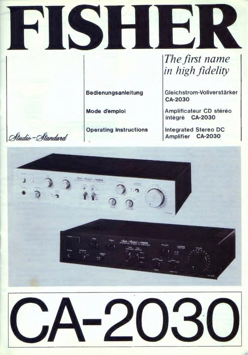
Fisher
Fisher CA-520 User manual

Fisher
Fisher CA-874 User manual