Fisherbrand AimStrip User manual

Table of Contents
Section 1 Introduction................................................................................................................1
Intended Use.............................................................................................................. 1
Section 2 Analyzer Components...............................................................................................2
Analyzer Component Illustrations............................................................................... 2
Section 3 Initial Startup..............................................................................................................3
Section 4 Analyzer Setup...........................................................................................................5
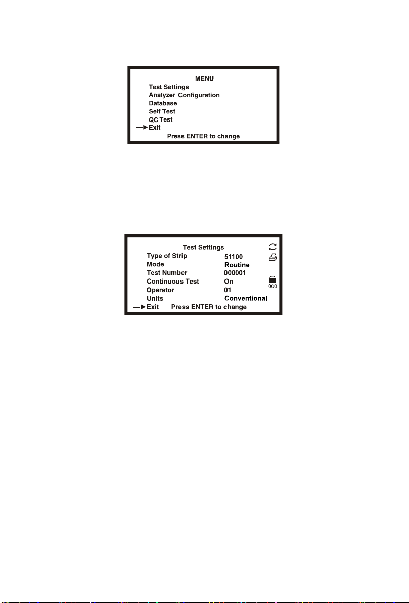
Test Settings..........................................................................................................5
Type of Strip............................................................................................................... 5
Mode.......................................................................................................................... 6
Test Number............................................................................................................... 6
Continuous Test ......................................................................................................... 7
Operator ID................................................................................................................ 7
Units...........................................................................................................................7
Analyzer Configuration.........................................................................................7
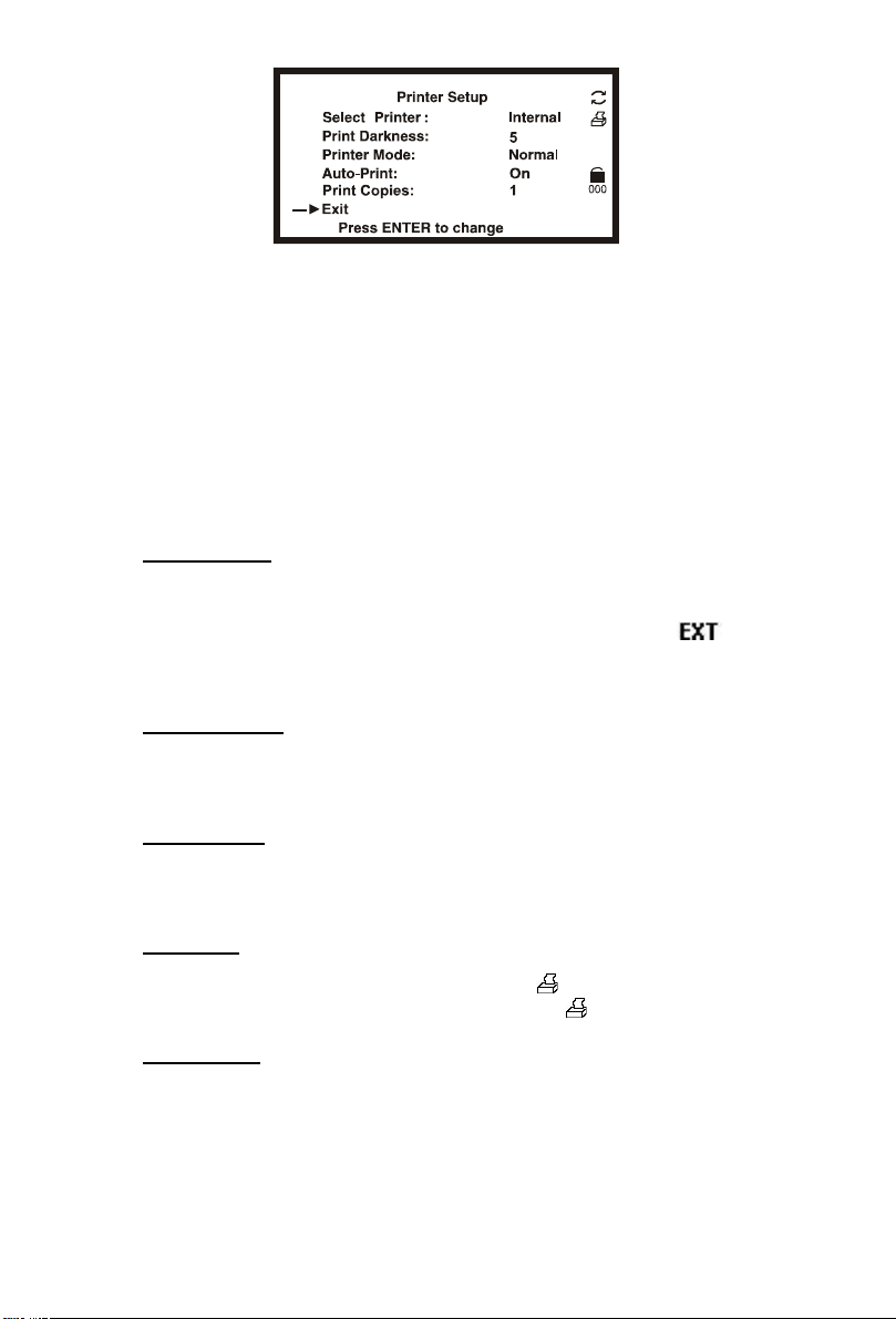
Printer Setup.............................................................................................................. 7
Sound......................................................................................................................... 8
Barcode reader.......................................................................................................... 9
Language................................................................................................................... 9
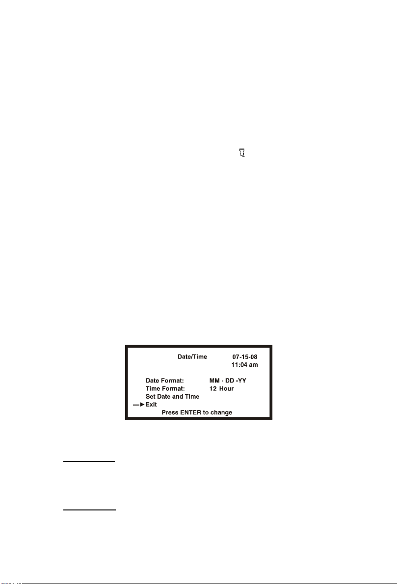
Date/Time................................................................................................................... 9
Auto Number Reset.................................................................................................. 10
Database...............................................................................................................10
Clear all Records.......................................................................................................11
Locate Record...........................................................................................................11
View Current Record.................................................................................................11
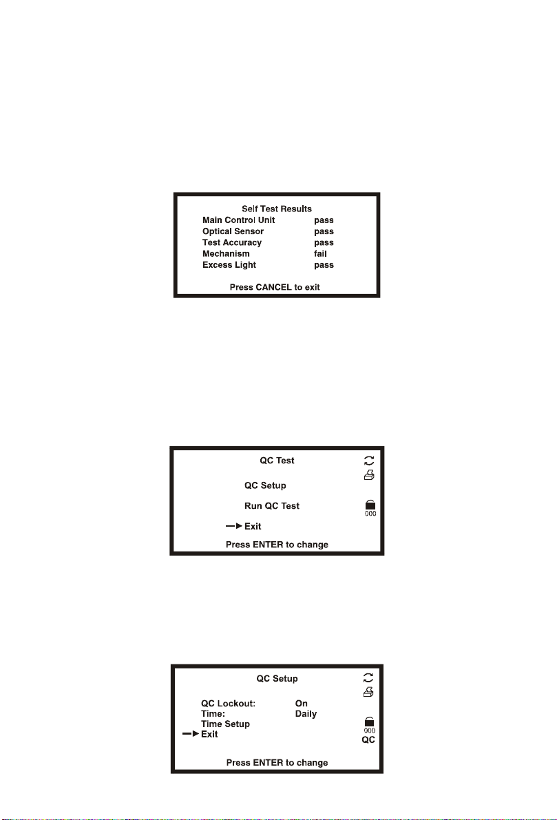
Self Test................................................................................................................12
QC Test.................................................................................................................12
QC Setup................................................................................................................. 12
Run QC Test............................................................................................................. 13
Setting the QC Values.............................................................................................. 14
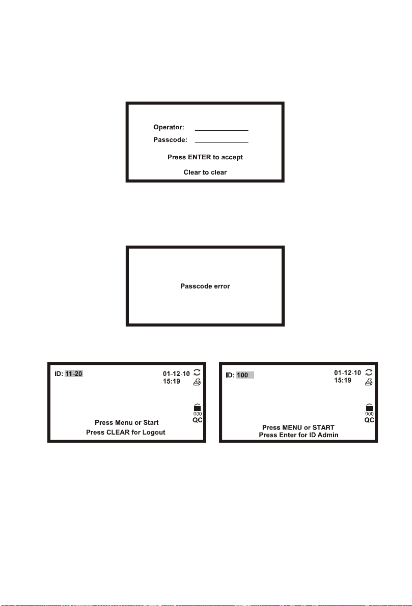
User Login............................................................................................................14
ID Admin .................................................................................................................. 14
Section 5 Analyzer Operation..................................................................................................17
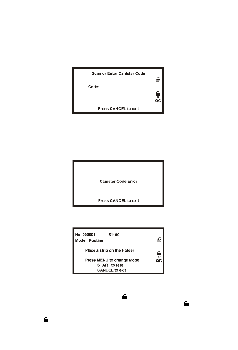
Entering Canister Code ......................................................................................19
Normal Operation, no Barcode reader ..............................................................20
Sample/Strip Preparation......................................................................................... 20
Strip Test – Single Test Mode................................................................................... 20
Strip Test – Continuous Test Mode........................................................................... 22
Normal Operation, Barcode reader installed....................................................23
Strip Test – Single Test Mode with Barcode reader.................................................. 23
Strip Test – Continuous Test Mode with Barcode reader.......................................... 24
Urine Controls QC Testing .................................................................................26
Strip Preparation ...................................................................................................... 26
Urine Control Test Procedures................................................................................. 27
QC lockout ...........................................................................................................27
Section 6 Data/Communication...............................................................................................29
External Printer ........................................................................................................ 29
Barcode reader........................................................................................................ 29
Section 7 Quality Control.........................................................................................................30
Section 8 Maintenance.............................................................................................................31
Loading Printer Paper.........................................................................................31
General Cleaning.................................................................................................32
Daily Cleaning......................................................................................................32
Remove the Strip Holder.......................................................................................... 32
Clean the Strip Holder.............................................................................................. 32
Load the Strip Holder............................................................................................... 32
Return the Strip Holder/Mount to its Internal Position............................................... 33
Sample Deposit Cleaning ...................................................................................33
Strip Holder Sterilization.....................................................................................33
Section 9 Precautions ..............................................................................................................34
Section 10 Troubleshooting.....................................................................................................35
Appendix 1 Urine Analyzer Specifications.............................................................................36
Appendix 2 Compatible Urinalysis Reagent Strips................................................................37
Appendix 3 Urinalysis Reagent Strips Parameter Table .......................................................43
Appendix 4 Result Print-Out....................................................................................................44
Appendix 5 Barcode reader.....................................................................................................45
Appendix 6 Catalog ..................................................................................................................46
Appendix 7 Index of Symbols..................................................................................................47
Appendix 8 Warranty................................................................................................................48

1
Section 1 Introduction
The AimStrip®Urine Analyzer and CTMI CT-120Analyzer read urine test strips. It
stores results and prints reports without the need for special training.
The AimStrip®Urine Analyzer and CTMI CT-120 Analyzer run a self-test each time
the power switch is turned on. An optional barcode reader records patient ID.
The barcode reader verifies strip canister barcodes. Use only AimStrip®and
Fisherbrand® Urinalysis Reagent Strips with the canister barcode for correct
results.
The AimStrip®Urine Analyzer and the CTMI CT-120 Analyzer are CLIA waived
when used with strips of the same brand as the analyzer. Only laboratories with a
Certificate of CLIA Waiver may use this analyzer in a waived setting. Users
should read this complete test procedure before performing a test using this
analyzer. Failure to adhere to these instructions for use and for performing QC
testing is considered off-label use. Off-label use is categorized as high complexity
and subject to all CLIA regulations.
Intended Use
The AimStrip®Urine Analyzer and the CTMI CT-120 Analyzer are intended for use
in conjunction with the AimStrip®and Fisherbrand®Urinalysis Reagent Strips for
the semi-quantitative detection of the following analytes in urine: Glucose, Bilirubin,
Ketone (Acetoacetic acid), Specific Gravity, Blood, pH, Protein, Urobilinogen, and
Leukocytes as well as the qualitative detection of Nitrite. The instrument is
intended for professional, in vitro diagnostic use only.
Note: Keys on the Keypad are listed in bold. Display items on the
screen are listed in bold italics in the manual.

2
Section 2 Analyzer Components
Analyzer Component Illustrations
1. Keypad
2. Liquid Crystal Display
3. Printer Cover
4. Paper Release Lever (green color)
5. Printer Roller
6. Printer Paper
7. Printer Cover Pull
8. Printer Paper Access Slot
9. Strip Holder
10. Strip Holder Channel
11. Strip Holder Stop
12. White Calibration Circle
13. Strip Holder Mount
14. USB Port
15. External Printer Port
16. Standard RS232C Port
17. Power Socket
18. Fuses
19. Power Switch

3
Section 3 Initial Startup
1. Place the analyzer on a level surface. Allow 20 cm on all sides of the analyzer
for access.
2. Plug the power cord into a power outlet. Press the power switch (19) located on
the back panel to turn the analyzer on. The analyzer will run a self-test. The
analyzer will display the screen shown below:
or
3. With no strip holder installed, the self test will fail indicating “Optical Sensor
Failed”. The Strip Holder Mount will be extended. Turn off the Power Switch.
4. Remove the Strip Holder from the plastic packaging. Position the white
Calibration Circle up and towards the back of the analyzer. It will slide loosely in
the locating channel. Push the Strip Holder in until it clicks into place. It will be
held firmly on the Strip Holder Mount. Ensure the Strip Holder is installed
properly. If it is not locked onto the Strip Holder Mount the analyzer will display
“Optical Sensor Failed.”
5. Turn the Power Switch on. The Self-Test will be run again. If the Self-Test
passes, the Initial Screen will be shown.

4
Note: The screen will not display if Strip Lockout is not included.
6. If the Self-Test fails, a Failed Screen will be displayed. The analyzer cannot be
operated. Press the power switch off then on again to re-test. Refer to Section
10 Troubleshooting to correct the failure. Ensure the Strip Holder is installed
properly.
7. Press MENU to access the Test Settings, Analyzer Configuration, Database
functions, Self-Test and QC Test.
Note: Use the arrow keys on the keypad to select Exit or press the
Cancel key when Exit is not available.
8. Press START to begin strip testing. Press ENTER for ID Admin.

5
Section 4 Analyzer Setup
Press Menu from the Initial Screen to display the screen below.
Select options by pressing ▲or ▼until the Selection Arrow (→) is next to the
option. Press ENTER to show the options in a new screen or cycle through the
settings below. Select Exit and press ENTER to return to the Initial Screen.
Test Settings
Select Test Settings to display the menu shown below.
Press ▲or ▼to select an option. Press Enter to show or change the option
settings below. Select Exit and press Enter to return to the Main Menu.
54100(4LN), 58100, and 51100(10SG) are examples of Type of Strips. Refer to
Appendix 2 for actual Analyzer-Read Type of Strips.
Type of Strip 54100(4LN), 58100, 51100(10SG)
Mode Routine, STAT, QC
Test Number User selected number
Continuous Test On, Off (single test)
Operator ID If User Login is off, Operator ID will be 01 through 10.
If User login is enabled, Operator ID will be 11
through 20, and 100 for the Administrator
Units Conventional Units or Standard International (SI)
Type of Strip
Select Type of Strip and press ENTER to change the strip type. Each strip type
name defines the number of test parameters. If User Login is enabled and
Operator ID is 11 through 20, this setting cannot be changed.
Refer to Appendix 2 for a detailed list of available parameters.
Note: Ensure the type of strip selected corresponds with the strip to be
used. If it does not, an error message will be displayed.

6
Mode
There are three test mode options. Press ENTER when Mode is selected to
change the Mode.
Note: The Mode can be changed during normal testing for STAT tests.
Routine Test
Use for normal urine testing. The default test number ranges from 1 to 99999. It
resets to 1 every day automatically if Auto Number Reset is set to Yes.
STAT Test
Use for emergency urine testing. The default test number is from 100001 to
199999. It resets to 100001 each day automatically if Auto Number Reset is set
to Yes. The analyzer will automatically switch to STAT test and can not be
changed if the QC test has failed.
QC Test
Use to test positive/negative controls. If QC lockout is on, this test will be run
automatically. The test number ranges from 200001 to 299999. It resets to
200001 every day automatically if Auto Number Reset is Yes.
Note: Ensure QC Test mode is used for testing positive and negative
controls. Use of any other mode will report the testing results as a
regular specimen and will not display proper “Pass/Fail” QC test
results.
Test Number
Select Test Number and press ENTER.
Enter the new Test Number. Press ENTER to confirm. Press CANCEL to
delete any changes and keep the existing number.
The first digit in the number will depend on the Test Mode. The first digit will be 0
for Routine, 1for STAT and 2for QC Test. This first digit is fixed and cannot be
changed from this screen. Tests run after this number is changed will be set
sequentially from the new number.
Note: Specimens may be assigned the same test number. They will be
distinguished by test date and time in the Database.

7
Continuous Test
Select Continuous Test and press ENTER to cycle the settings to Off or On.
When the selection is correct, select EXIT and press ENTER to return to the Main
Menu.
Continuous Test – Off (Single Test Mode)
Test one strip at a time. Single Test Mode performs 60 tests / hour.
Continuous Test - On
Test strips one after another. Continuous Test Mode performs up to 120 tests
per hour. When Continuous Test is on, the symbol will be displayed.
Operator ID
Select Operator ID and press ENTER to increase the number by one. After 10, it
reverts back to 01. If User Login is enabled and Operator ID is 11 through 20,
this setting cannot be changed. Select EXIT and press ENTER to return to the
Main Menu.
Units
Select Units and press ENTER to cycle the units between Conventional or SI
units. If User Login is enabled and Operator ID is 11 through 20, this setting
cannot be changed. Select EXIT and press ENTER to return to the Main Menu.
Note: Arbitrary results will always be printed.
Analyzer Configuration
Select Analyzer Configuration from the Main Menu to display the screen below.
Press ▲or ▼to move →to make changes. After all changes are made, select
EXIT and press ENTER to save changes and return to the Main Menu. If User
Login is enabled and Operator ID is 11 through 20, this Menu cannot be changed.
Printer Setup
Select Printer Setup to display the screen below.

8
Press ▲or ▼to move →to select the options listed below. Press ENTER to
change the option as shown below.
Select Printer Internal or External
Print Darkness 1 through 9
Printer Mode Normal or Expand fonts
Auto-print On or Off
Print Copies 1 to 3
Select Exit and press ENTER to save changes. The screen will then return to the
previous Menu.
Select Printer
Internal prints the results on the internal printer.
External prints the results on an external printer. The symbol will display
on all screens. Contact Germaine Labs Technical Support for a list of printers and
printer cables that can be used.
Print Darkness
Print darkness ranges from 1to 9. The darkest is 9. After 9it reverts back to 1.
The default is 5.
Printer Mode
Normal prints the standard font size and saves paper. Expand prints a larger
font size and uses more paper.
Auto-print
Auto-print On prints the results after each test. is displayed. Auto-print Off
requires pressing the Print key to print the results. is not displayed.
Print Copies
Print Copies defines the number of result copies printed at one time. Print
Copies can be set from 1 to 3.
Sound
Select Sound and press ENTER to cycle the options to Off, On and Prompts.
These options function as listed below.

9
Off – internal speaker is Off in all cases
On – Internal speaker is On in all cases (keyboard and prompts)
Prompts – Internal speaker is On only for prompts to the operator.
Select Exit with →and press ENTER to save changes. The screen will return to
the Main Menu.
Barcode reader
Select Barcode reader and press ENTER to display Yes to allow Barcode reading.
Press ENTER to cycle between Yes or No. Yes displays prompt for full usage of
the Barcode reader. The Barcode reader icon will be shown. If the optional
Barcode reader is not present, this setting should be set to No.
Select Exit with →and press ENTER to save changes. The screen will return to
the Main Menu.
Language
Select Language and press ENTER to change the current language. Each time
ENTER is pressed the language changes.
Select Exit with →and press ENTER to save changes. The screen will return to
the Main Menu.
Date/Time
Select Date/Time and press ENTER to display the screen to change the date/time
as shown below.
Select Exit and press ENTER to save changes. The screen will return to the
previous Menu.
Press ▲or ▼to move →to the options listed below. Press ENTER to change the
selected option.
Date Format
Select Date Format and press ENTER to cycle to MM-DD-YY, YY-MM-DD or
DD-MM-YY.
Time Format
Select Time Format and press ENTER to cycle to 24 Hour or 12 Hour. 12 Hour
displays the time with am/pm symbols.

10
Set Date and Time
Select Set Date and Time and press ENTER to display a new screen for setting
the current date and time.
The first digit to be changed in the date will be highlighted. Press ▲or ▼to
change the number one at a time. Continue to press ▲or ▼until the correct
number is shown. Press ◄or ►to progress to the next digit to be changed.
Press ▲or ▼to increase or decrease the number. Change each of the time and
date digits/fields in this manner. Press ENTER to save the changes and exit the
screen. Press CANCEL to not accept any changes and exit the screen. Either
key will return to the previous screen.
Auto Number Reset
Select Auto Number Reset and press Enter to cycle to Yes or No. If Yes, the
test number will reset to 000001, 100001 or 200001 for Normal, STAT or QC
modes each day. If No the test number is unaffected by date.
Database
Select Database and press ENTER to display the screen below.
Press ▲or ▼to move →to enter each screen and make changes. After all
changes are made press ENTER to save changes and return to the Main Menu.
Up to 2000 records can be stored in memory. If User Login is enabled and
Operator ID is 11 through 20, the operator can only review data stored in the
analyzer.
Caution: Use a number higher than the previous test number.
If there are 2000 records stored in memory, the oldest record will be erased and
replaced.
Records may have the same number but different dates and times.

11
Clear all Records
Select Clear all Records and press ENTER. If User Login is enabled and
Operator ID is 11 through 20, the analyzer will not respond.
Press ENTER to delete all records. A prompt will appear. Once records are
deleted they cannot be recovered. The Test Number will reset to 000001,
100001 or 200001 depending on the Test Mode. Press any other key to cancel.
The screen will return to the Database Menu.
Locate Record
Select Locate Record and press ENTER.
Press the number keys to enter the Test Number and/or test Date. Press Enter
to view the results.
If only the Test Number is entered records with the current Date will be searched.
If there is no Test Number with the current Date, the latest previous Date will be
searched. For example, assume the current date is 2007-03-27. There are two
records with the same Test Number but dates of 2007-03-26 and 2007-03-20.
The test from 2007-03-26 will be displayed.
If there is no record found Record not found will be displayed. Press any key to
return to the Database Menu.
Press Print to print a record.
Press ▼to view the previous record. Press ▲to view the next record.
Press CANCEL to return to the previous screen. Additional records can be
located, reviewed or printed.
View Current Record
Select Current Record and press ENTER to show the data from the current or last
record.

12
Press Print to print a record once it is displayed.
Press ▼to view the previous record. Press ▲to view the next record.
Press CANCEL to return to the previous screen.
Self Test
Select Self Test and press ENTER to perform self tests. A results screen will
display the results of each test.
After each test, a pass or fail is displayed on the screen. If any results fail, the
unit will not operate. Refer to Section 10 Troubleshooting.
Press CANCEL to return to the Main Menu.
QC Test
Select QC Test and press ENTER. If User Login is enabled and Operator ID is
11 through 20 the operator can only view settings and run a QC test.
Press ▲or ▼to move →to make changes. Select Exit and press ENTER to
save changes.
QC Setup
Select QC Setup and press Enter.

13
QC Lockout
Select QC Lockout and press ENTER to cycle the options Off or On.
Off disables the QC lockout function. The QC symbol and Setup Options are not
displayed.
On enables the QC lockout function. The QC symbol is displayed. QC Lockout
timing can be set for Every 8 Hours, Daily, Weekly or Monthly.
Time
Select Time and press ENTER to set the QC test for Every 8 Hours, Daily,
Weekly or Monthly.
Time Setup
Select Time Setup and press ENTER.
Every8Hours/Daily Weekly/Monthly
The first highlighted digit will be changed. Press ▲or ▼to change. Continue to
press ▲or ▼until the correct number is shown. Press ◄or ►to progress to the
next digit to be changed. Press ▲or ▼to increase or decrease the number.
Change each of the time and date digits/fields in this manner until the desired date
is shown. Press ENTER to save the changes and exit the screen. Press
CANCEL to not accept changes and exit.
There is no Date Setup if QC tests are set for Every 8 Hours or Daily.
For the Monthly option, Date can be set from 01 to 28. 29, 30and 31 are invalid.
Run QC Test
Select Run QC Test and press ENTER to perform a QC test before the next
scheduled test time.
When a QC test is run for the first time, the analyzer will show the screen below if
QC values have not been set up.

14
Setting the QC Values
From the Initial Screen, enter the passcode 420024 to show the QC value setup
screen.
Press ▲or ▼to change the highlighted digit. Press ◄or ►to move to the digit
to be changed. Press ▲or ▼to increase or decrease the value. Change each
of the analyte QC values in this manner until the desired values are shown.
Press ENTER to save the changes and exit the screen. Press PRINT to print the
current values.
User Login
Press ENTER from the Initial Screen to show the Administrator login screen. The
Operator ID is preset to 100.
On entry to this screen for the first time, leave the Passcode blank and press
ENTER.
Press CANCEL to return to the Initial Screen without enabling User Login.
ID Admin
The Administrator screen is shown.

15
Press ▲or ▼to move the →to make changes. If Passcode is blank, user login
is not yet enabled and only Change Admin Passcode can be chosen. Select
Exit and press ENTER to save changes.
Change Admin Passcode
Change the passcode from blank to a valid passcode, select Change Admin
Passcode and press ENTER.
A non-blank passcode must be entered to enable User Login. If a blank is
entered, a new screen will indicate the passcode is invalid. After 3 seconds, the
screen will return to the login screen.
Press CANCEL to keep the existing passcode and exit.
Scan or enter a valid Passcode and press ENTER to accept and exit. User
Login will be enabled.

16
Operator Setup
After User Login is enabled, select Operator Setup and press ENTER.
Xindicates the ID is enabled. Oindicates the ID is not enabled.
Press ◄or ►to move the cursor to the desired ID. Press ENTER for the
Passcode screen.
Scan or enter a new Passcode. Press ENTER to save the settings and exit.
Press CANCEL to cancel the settings and exit. Enter a blank Passcode to
disable the ID.
Logout
After the User Login is enabled, select Logout and press ENTER to log out. The
normal Login screen will be shown for a new operator login. See Section 5 for
Login procedures.
Press CLEAR from the Initial Screen to logout and display the Login Screen shown
above.

17
Section 5 Analyzer Operation
If User Login is not enabled, the Initial Screen will be shown after Self Test.
Refer to Section 3 Initial Startup.
If User login is enabled, the analyzer will display a login screen after Self Test.
Enter the ID and enter or scan the Passcode. Press ENTER to run the analyzer.
Press CLEAR to return to the login screen.
If the Passcode is incorrect, the analyzer will indicate a passcode error. After 3
seconds, the screen will return to the login screen.
If the Passcode is correct, the analyzer will display the Initial Screen. The
logged-in ID will be shown (11-20, or 100).
The user ID will be 11-20 for Operators. This provides access to operate the
analyzer, change test modes and test number, and review settings. Press
CLEAR from the Initial Screen to logout and display the Login Screen.
The user ID will be 100 for the Administrator. This provides full access to operate
the analyzer and change settings. Press ENTER from the Initial Screen to display
the ID Admin Screen. Press CLEAR from the Initial Screen to logout and display
the Login Screen.
Press START on the Initial Screen to test strips. Check all settings and strip types
before testing.

18
During testing, the screens will display icons showing the status, options available
and prompts for testing:
No.
000001
The sequential test number assigned to the next test to be run. In
Routine Mode, the first digit will be 0. In STAT Mode, the first digit
will be 1. In QC Mode, the first digit will be 2.
51100
(10SG)
Indicates the proper strip to be tested has 10 test pads. Standard
strips available are 4, 8, or 10 test parameters, refer to Appendix 2.
Select the strip configuration using the MENU function from the Initial
Screen. The strip type must match the strip being used or result will
not be displayed.
Mode
Indicates the current mode setting. Available modes are Routine,
STAT and QC. Press ENTER from this screen to change the mode.
Continue to press ENTER to cycle through each mode. The mode
may be changed when this prompt appears.
When visible, Continuous Test is set to test up to 120 tests per hour.
If not, Single Test is set to test one strip at a time up to 60 tests per
hour.
When visible, the printer is set to Auto-print. Test data is sent to the
internal printer and data ports after each test. Results are displayed
on the screen. If this icon is not visible, press Print to send results to
the printer and data port.
When visible, Auto-Print is On. Test data is sent to the external
printer and data ports after each test.
When visible, indicates the Barcode reader is enabled.
If only EXT is visible, Auto-Print is Off. Press Print to send test data
to the printer and data port.
Strip Lockout is available. The analyzer will only test strips with correct
barcodes. There will be no symbol if Strip Lockout is not an included
function.
QC When visible, indicates QC Lockout is On. When the scheduled test
time arrives, this symbol will flash. A beep will be heard to prompt
that a QC test is required before performing additional tests.

19
Entering Canister Code
When a new canister of strips is required, the analyzer will request that a canister
code is entered from the new canister. The code can be entered manually from
the keypad, or scanned with the Barcode reader, if installed.
At first startup, the Strip Holder will fully extend. The screen below will be
displayed.
Scan or manually enter the canister code from the strip canister. Press CLEAR to
move the cursor to the proper digit. Edit the number as needed. After the last
digit of the correct code is entered, the next screen will be shown. Press
CANCEL to cancel the changes and exit the screen.
If the canister code is incorrect, the following screen will show.
Press CANCEL to exit to the previous screen.
If the canister code is correct, the analyzer will proceed to the Initial Screen.
Note: Refer to Section 4, Analyzer Setup, to change the settings.
When there are only 5 strips remaining, will flash to prompt that a new canister
of strips is required. The number of strips left can be seen under .
When the current run is completed, enter the new canister code. The number
under will be increased accordingly.
This manual suits for next models
1
Table of contents
Other Fisherbrand Measuring Instrument manuals
Popular Measuring Instrument manuals by other brands

EUTECH INSTRUMENTS
EUTECH INSTRUMENTS Oakton CON 510 instruction manual

Awite
Awite AwiFLEX XL Original instruction manual

POWERSIDE
POWERSIDE PQube 3 installation manual

Fluidwell
Fluidwell D Series manual

LaserLiner
LaserLiner GreenLine-Laser 2 P operating instructions

Hanna Instruments
Hanna Instruments HI9811-51 instruction manual

Savant
Savant SmartEnergy SEM-1024 Quick reference guide

SCIENTIFIC INSTRUMENTS
SCIENTIFIC INSTRUMENTS SCM10 manual

autosen
autosen AS005 operating instructions

ELEC-MECH
ELEC-MECH SAFE-AID TS350 Operator's manual

KROHNE
KROHNE OPTISWIRL 4200 quick start

Endress+Hauser
Endress+Hauser PROline promag 53 operating instructions