manuals.online logo
Brands
  1. Home
  2. •
  3. Brands
  4. •
  5. Fishman
  6. •
  7. Accessories For Musical Instruments
  8. •
  9. Fishman PowerTap Infinity User manual

Fishman PowerTap Infinity User manual

1
POWERTAP INFINITY INSTALLATION GUIDE
514-300-184_r1
Read Me First!
*We recommend having this PowerTap system installed
by an experienced repair technician.
**Dry fit all internal components (Volume & Tone
Module, Blend Module and Tap Body Sensor to ensure
proper fit before installation.
PICKUP INSTALLATION
Saddle Slot Requirements:
Minimum saddle slot length: 2.775” (70.4mm)
Maximum E to E spacing at saddle: 2.5” (63.5mm)
Observe the following precautions!
•Handle the pickup carefully. Do not trim the
pickup to make it fit. Mishandling may tear the delicate
foil shield, producing ground hum or intermittent signal.
•Do not shorten the pickup wire. This will result
in poor pickup performance and loss of bass response.
•Both the saddle and saddle slot must be flat and
square for proper pickup performance and balance.
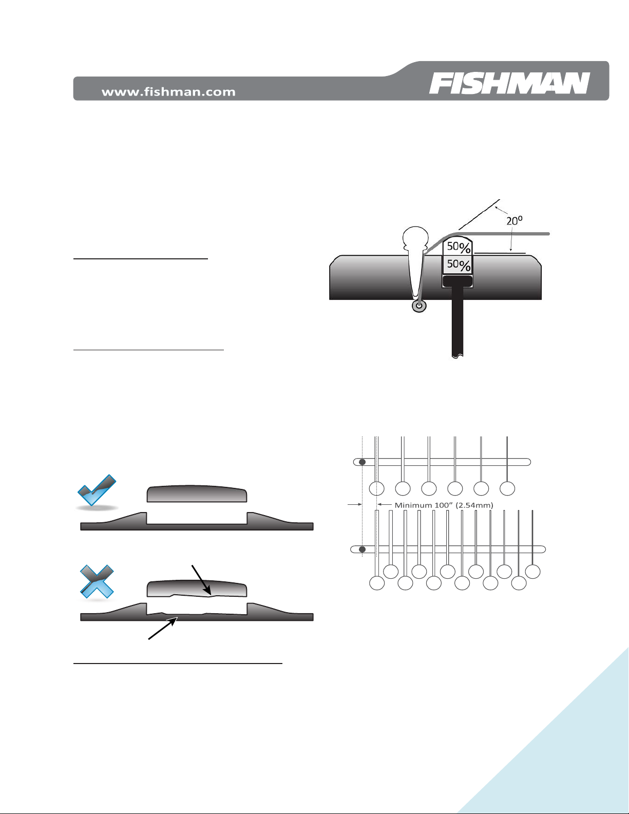
Mechanical factors affecting pickup performance
•Break Angle: To assure optimum pickup
performance, there should be a 20° (minimum) string
break angle across the back of the saddle. *
•The 50/50 Rule: There is an important
relationship between the overall saddle height and the
bridge slot depth. We suggest that the saddle slot depth
(with pickup installed) measures 50% of the total height of
the saddle. If the slot measures greater than 50% the total
height of the saddle, balance and/or output level of the
pickup may suffer*
*Minimum 20⁰ string break angle
Locate the wire hole
1. Locate the center of the wire hole a minimum of .100”
(2.5mm) from the closest string.
2. Mark the location where the wire will enter the saddle
slot. Center the mark between the walls (width) of the
slot and drill a .094” hole.
3. Clear wood chips and foreign materials from the saddle
slot.
4. Carefully insert (do not bend) the pickup. The pickup
must fit loosely in the slot, without binding. If the corners
of the pickup touch the radiused ends of the saddle slot,
pickup failure could result.
- 2 -
Pickup Installation continued…
Prepare the saddle
You may re-use your original saddle after the pickup is
installed. To maintain your current action, you must
remove material from the bottom of the saddle to
compensate for the added height of the pickup. For
Wide format pickups, remove .053” of material. For
Narrow format pickups, remove .043” of material.
New Saddle requirements
Organic saddles (Bone or Ivory) are not structurally as
consistent as synthetic materials and may not produce
optimal string balance through the pickup. Synthetic
materials such as Micarta™ or Corian™ are suggested.
Prepare a new saddle that fits properly in the saddle
slot. The bottom of the saddle must be flat.
Remove only enough material from the width of the
saddle to provide a sliding fit in the slot. To test for
proper fit before stringing the instrument, turn the
instrument upside down. The saddle should remain in
the slot. You should be able to remove it easily with your
fingers. If you need tools to remove it, it’s too tight!
PREAMP INSTALLATION
Note: For nylon string instruments refer to the
Installation Options later in this install guide
After the pickup is installed in the guitar, it’s time to
attach it to the preamp.
Prepare the endpin jack hole by drilling a 15/32” hole in
the intended location of the jack. (If the guitar has an
existing strap button, you will enlarge that hole to
15/32”)
Open the preamp housing to expose the pickup input
terminal block
Bring the pickup wire out through the soundhole and
fasten it to the terminal block on the preamp module.
- 3 -
Preamp Installation continued…
The signal wire goes to the terminal marked “IN”
and the shield goes to the “GND” terminal.
Reminder: Do not shorten the pickup wire. Tighten
the screws on the terminal block to secure the wire.
Replace the preamp’s cover being sure the wires do
not get pinched by any plastic parts. The housing
should easily fasten tightly when the screw is
replaced.
Fasten the Preamp/Jack in the Endpin Hole
Follow this sequence when installing the endpin jack:
1 - Large Hex nut
2 - Large Dress Washer
3 - Star Washer
Guitar End Block
4 - Small Dress Washer
5 - Small Dress Nut
6 - Strap Button
Thread the large nut, dress washer and star washer down the
jack towards the preamp body to allow the proper amount of
the jack to go through the end block.
For proper fit, the Endpin Jack should protrude at least 5/16"
(7.9 mm) and no more than 11/32" (8.7mm) outside the
guitar's body.
Fit the small dress washer and nut over the end of the jack
and tighten the nut with a 1/2" open-end wrench while
counter-holding the jack in place with an Allen wrench or
small screwdriver.
- 4 -
Preamp Installation continued…
Thread and gently tighten the strap button using rubber
tipped pliers.
Note: With the strap button in place, the end of the jack
should protrude slightly, so that when a plug is inserted,
it will snap securely in place.
Tap Body Sensor Installation
Next, install the Tap Body Sensor. The Body Sensor
installs onto the bridge plate of the instrument directly
under the saddle. Make sure the area where the body
sensor will mount is smooth. Clean this surface with an
alcohol wipe or a cotton swab moistened with rubbing
alcohol. Let dry.
Use the included mounting tool and two golf tee locaters to
ensure proper placement of the Tap Body Sensor.
- 5 -
Tap Body Sensor Installation continued…
To properly mount the Tap Body Sensor, insert it as
shown into the mounting tool.
Note: Before proceeding with the next 5 steps, practice
installing the Tap Body Sensor a few times with the backing
paper still attached to the pickup.
1. Peel off backing paper and add 3 small drops of
Gel Type Cyanoacrylate (Super Glue) One in the
center and ½” in from each end of the sensor.
1. Hold the sensor in the mounting tool inside the
guitar in the area of the bridge plate under the
bridge. (Do not press the pickup against the
bridge plate at this time)
2. Using one of the golf tee locator pins, insert it
through the “A” string bridge pin hole and into the
round hole in the corner of the mounting tool. Using
the second golf tee, insert it through the “B” string
bridge pin hole and into the slotted hole in the
opposite corner of the mounting tool.
Inside view:
Top View:
- 6 -
Tap Body Sensor Installation continued…
3. With both locator pins inserted, gently push the
sensor into place on the bridge plate. Hold
against the bridge plate with firm pressure for
30 seconds.
Once the sensor is attached to the bridge plate
remove the mounting tool and golf tees.
VOLUME & TONE MODULE and BLEND
MODULE
The PowerTap Infinity comes ready to install into a steel
string instrument. For steel string instruments, move to
the next step: Volume & Tone Module Installation
For Control Module Installation in a Nylon String Guitar
see: Classical Style Control Modules on page 8
Volume & Tone module Installation
Control Module locations:
Test the area where you will mount the Volume & Tone
control module. Remove any lacquer and/or buffing
compound from this area using fine grit sandpaper. Clean this
surface with an alcohol wipe or a cotton swab moistened with
rubbing alcohol. Let dry.
Note: For the strongest bond we recommend a water-based
primer/sealer be applied to the bare wood inside the
soundhole. A light film of yellow wood glue spread by
fingertip works well for this application. Let the primer/ sealer
dry before continuing.
Peel back the release film on the bottom of the control
module, add a small dot of gel type cyanoacrylate to the
center of the adhesive and fasten the preamp to the
underside of the soundhole. Locate the module flush with the
edge of the soundhole, on the bass side, between the
transverse brace and the bass-side x-brace (see illustration).
Apply even, steady pressure to the module for 30-45 seconds
to set the adhesive. The adhesive achieves maximum hold
after 24 hours.
- 7 -
Blend Module Installation
Note: Repeat the Control Module Installation steps to
install the Blend module on the opposite (pickguard) side
of the soundhole.
Battery Bag Installation
Install the battery bag in your desired location inside the
guitar. The two most prominent locations for this are the
neck block or on the back of the guitar in the shoulder
area.
Clean the area where you will mount the bag with an
alcohol wipe or cotton swab moistened with rubbing
alcohol. Let dry.
Note: It is important to make sure the area is clean and
free of dust or any foreign matter that will compromise
the adhesive.
Separate the battery bag and Hook and Loop patch. Peel
off the plastic film from the hook and loop patch and
place it in the chosen location. To set the adhesive,
burnish the entire area of the patch, especially the
edges.
Connect a 9V battery to the battery cable and tuck it into
the bag. Press the bag firmly onto the hook and loop
patch inside the instrument. The adhesive under the
patch requires 24 hours to achieve a full bond.
Secure the wires inside the instrument with the supplied
adhesive-backed clips. Clean the bare wood surface where
you will fasten the clips. Use an alcohol wipe or a cotton swab
moistened with rubbing alcohol.
- 8 -
Classical Style Control Modules
For nylon string guitars, or steel string guitars with
unique bracing patterns, remove the top cover of the
Volume & Tone module and the Blend module and
replace them with the alternate supplied classical
covers.
To convert the steel string mounts to classical mounts,
remove the adhesive on the cover to expose the small
Philips head screw. Remove and place the screw aside as
you will need it to attach the classical cover.
On the back end of the module, remove the 1.5mm hex
screw and place it aside as you will need this screw to
attach the classical cover.
Remove the steel string cover(s) and replace it with the
classical cover(s) using the original Philips and 1.5mm
screws. After both screws are in place, the control
module(s) are ready to install into the guitar. Return to
Volume & Tone Module Installation on page 6

Other manuals for PowerTap Infinity

1

Other Fishman Accessories For Musical Instruments manuals

Fishman FLUENCE CLASSIC User manual

Fishman

Fishman FLUENCE CLASSIC User manual

Fishman FLUENCE TIM HENSON SIGNATURE Series User manual

Fishman

Fishman FLUENCE TIM HENSON SIGNATURE Series User manual

Fishman RARE EARTH - User manual

Fishman

Fishman RARE EARTH - User manual

Fishman ACOUSTIC MATRIX NATURAL I User manual

Fishman

Fishman ACOUSTIC MATRIX NATURAL I User manual

Fishman SONITONE User manual

Fishman

Fishman SONITONE User manual

Fishman PowerTap Earth User manual

Fishman

Fishman PowerTap Earth User manual

Fishman RARE EARTH BAJO QUINTO User manual

Fishman

Fishman RARE EARTH BAJO QUINTO User manual

Fishman SONITONE User manual

Fishman

Fishman SONITONE User manual

Fishman NEO-BUSTER PRO-NEO-FB2 User manual

Fishman

Fishman NEO-BUSTER PRO-NEO-FB2 User manual

Fishman Fluence series User manual

Fishman

Fishman Fluence series User manual

Fishman NASHVILLE Series User manual

Fishman

Fishman NASHVILLE Series User manual

Fishman TriplePlay User manual

Fishman

Fishman TriplePlay User manual

Fishman FLUENCE SB1 User manual

Fishman

Fishman FLUENCE SB1 User manual

Fishman FLUENCE CUSTOM MATT HEAFY Series User manual

Fishman

Fishman FLUENCE CUSTOM MATT HEAFY Series User manual

Fishman ELLIPSE BLEND - User manual

Fishman

Fishman ELLIPSE BLEND - User manual

Fishman RARE EARTH - User manual

Fishman

Fishman RARE EARTH - User manual

Fishman FLUENCE SIGNATURE RICHARD Z Series User manual

Fishman

Fishman FLUENCE SIGNATURE RICHARD Z Series User manual

Fishman SONITONE User manual

Fishman

Fishman SONITONE User manual

Popular Accessories For Musical Instruments manuals by other brands

K&K Sound PURE RESONATOR SB product manual

K&K Sound

K&K Sound PURE RESONATOR SB product manual

K&K Sound PURE PIANO product manual

K&K Sound

K&K Sound PURE PIANO product manual

Kinman Hx Installing

Kinman

Kinman Hx Installing

Roland GT-8 quick start guide

Roland

Roland GT-8 quick start guide

Aion Electronics MERIDIAN manual

Aion Electronics

Aion Electronics MERIDIAN manual

FuzzDog Stinky Cheese manual

FuzzDog

FuzzDog Stinky Cheese manual

EMG ALX SET Installation information

EMG

EMG ALX SET Installation information

Opus-Two Instrument Control System Operation manual

Opus-Two

Opus-Two Instrument Control System Operation manual

PIRASTRO KorfkerRest LUNA instruction manual

PIRASTRO

PIRASTRO KorfkerRest LUNA instruction manual

EMG PASSIVE Installation information

EMG

EMG PASSIVE Installation information

EHX PICO ATTACK DECAY user manual

EHX

EHX PICO ATTACK DECAY user manual

FuzzDog Recurring Nightmare instructions

FuzzDog

FuzzDog Recurring Nightmare instructions

Auralex GeoFusor-22 Installation & user guide

Auralex

Auralex GeoFusor-22 Installation & user guide

K&K Sound VIOLINISSIMO product manual

K&K Sound

K&K Sound VIOLINISSIMO product manual

SUSTAINIAC GA-2 manual

SUSTAINIAC

SUSTAINIAC GA-2 manual

Kinman P-90 Mounting Plate Installing

Kinman

Kinman P-90 Mounting Plate Installing

EMG 81 Installation information

EMG

EMG 81 Installation information

String Effects Guitar-Jo instruction manual

String Effects

String Effects Guitar-Jo instruction manual

manuals.online logo
manuals.online logoBrands
  • About & Mission
  • Contact us
  • Privacy Policy
  • Terms and Conditions

Copyright 2025 Manuals.Online. All Rights Reserved.