manuals.online logo
Brands
  1. Home
  2. •
  3. Brands
  4. •
  5. EMG
  6. •
  7. Accessories For Musical Instruments
  8. •
  9. EMG AB 220 Service manual

EMG AB 220 Service manual

0.025 LOG FREQ (kHz) 20
10 dB/div
Dimensions:
.975
.650
CLICK 1 (+8db)
CLICK 2 (+15db)
MAXIMUM
UNITY
MAX (+20db)
INPUT
GROUND
GROUND
OUTPUT
V++
AB 220
SPECIFICATIONS
Input Impedance (Ohms) 250K
Input Referred Noise -130dbV
Output Impedance (Ohms) 2K
Current @ 9V (Microamps) 980
Battery Life (Hours) 250
Maximum Supply (Volts DC) 18
INSTALLATION INFORMATION
EMG MODEL: AB 220
(ACTIVE/PASSIVE PICKUP INPUTS)
Warranty
All EMG Pickups and accessories are warranted for a period of two years. This warranty does not cover failure due to improper installation, abuse or damage. If
upon examination the pickup is determined to be defective, a replacement will be made. Warranty replacement products are covered by this same warranty. This
warranty covers only those pickups and accessories sold by authorized EMG Dealers. This warranty is not transferable.
© 2014 Copyright EMG INC. All Rights Reserved.
PO BOX 4394
SANTA ROSA, CA
95402 USA
P (707) 525-9941
F (707) 575-7046
EMGPICKUPS.COM
0230-0291A
Frequency Response and Gain:
EMG-AB 220
1.325
.400
.309
(8mm)
GENERAL OPERATION and INSTALLATION NOTES:
The AB 220 is a full bandwidth boost circuit with a maximum of +20db of gain. It features two detented positions, the first at +8db, the second
at +15db. It can operate on a single 9 volt battery and can be easily installed in any guitar with active or passive pickups. It can also be used for bass.
When the control is turned all the way down (counter-clockwise) it is in the bypass mode.
The AB 220 is wired in series with the signal path and should be the last effect in the guitar, just before the output jack.
If you have EMG Active pickups, the installation is very simple, If you have passive pickups, either EMG or other, and your instrument does not have a
battery, you will need to make space for a battery and change the output jack to a stereo type similar to the one included with the AB 220.
Connector for EMG Active Tone controls
and accessories.
Pin 1 Input
Pin 2 Ground for Input
Pin 3 Ground for Output
Pin 4 Output
Pin 5 V+ Supply
1
2
3
4
5
1 2 3 4 5
(10)
(33.6)
(16.5)
(24.7)
INCLUDED:
1 AB 220 Boost Control
1 Battery Clip with Buss Connector
1 Stereo Output Jack (Battery Switching)
2 Interconnect cables
NOTE REVERSED CONNECTOR
VOLUME
B122rH
Diagram #1
Like all EMG Accessory products, the AB 220 uses a 5-pin connector.
Diagram #1 to the right shows how the plug-in connectors are installed.
Be sure to reverse the input connector as shown.
As mentioned in the General Operation note on page 1, the AB 220 should be
the last effect in the signal chain. The diagrams all show the installation in this manner.
The output jack included with the AB220 is a stereo type and is used to turn the
battery off when the guitar is unplugged. If you have a long panel jack, make sure
you have a stereo jack, the Switchcraft type is 152B.
Diagram #2 shows the simplest installation. A pig-tail connector is supplied
so you can solder it to the pickup cable, then plug into the AB220, or if you
have EMG Cables you can simply use those.
Diagrams #3 and #4 illustrate Active EMG installations that have a single pickup and
do not use a selection switch.
Page 3 has diagrams that have 2 pickups and a selection switch.
Page 4 has diagrams that have 3 pickups and use the B161v4 five position
selection switch/buss. If you have the B161v4, refer to that data sheet where
more options regarding the 3-pickup instruments are available.
Keep in mind that all of the EMG Accessory controls can be substituted for one
another since they all have buffered inputs and utilize the same 5-pin connnector.
So, if you decide you would rather use the SPC instead of the AB 220, simply unplug
the Boost and replace it with the SPC.
Installation Instructions:
EMG Model: AB 220
AB 220 Page 2
Note: Reversed connector! Pins 1 and 2 are reversed.
Make sure the connectors are plugged on as shown.
All of the EMG Active controls use the same 5-pin connector
shown below.
Diagram #2
T
R
S
FROM PICKUP
BATTERY
NEG (-)
RED
RED
OUTPUT CABLE
MASTER
VOLUME
- 9V +
BATTERY
BUSS
Diagram #3
One Pickup
One Volume
One AB 220
AB 220
INPUT
GROUND
EMG CABLE
TYPICAL OUTPUT CABLE WITH PIGTAIL ATTACHED
BATTERY
NEG (-)
OUTPUT CABLE
- 9V + OUTPUT
T
R
S
AB 220
MASTER ACTIVE TONE
(VLPF)
NOTE REVERSED CONNECTOR
VOLUME
B122rH
TONE
B124rH
VOLUME
B122rH
VOLUME
B122rH
NECK PICKUP
BRIDGE PICKUP
BATTERY
NEG (-)
RED
RED
RED
GROUND
BRIDGE P/U
NECK P/U
OUTPUT
- 9V +
NK VOLUME
BR VOLUME
T
R
S
OUTPUT CABLE
Powering up the pickups:
If your existing active pickup cables don’t have the connector for the
power buss, simply use some needle nose pliers and pull out the
V+ header and solder the RED Wires of the EMG Pickups to any
of the pins on the header.
Solder RED wires from both
EMG Pickups and the
RED wire of the Battery Clip
and re-insert the Header
into the insulation cover
123
2 Pickup Guitars using a selection switch:
Diagrams #5 and #6 show the pickups connected to the B245 Pickup Buss.
To learn more about the B245 Pickup Buss, be sure to go to the EMG Website:
http://www.emgpickups.com. More diagrams are available at the EMG website.
The ABA 220 or any EMG Active Tone Control is shown following the pickup buss
and then to the output jack.
AB 220 Page 3
Diagram #5
2 Pickups
Toggle Style Switch
Volume each Pickup (Volumes are independent)
AB 220 Control
Diagram #4
One Pickup
One Volume
One Master Tone
One AB 220
MASTER TONE
OUTPUT
T
R
S
FROM PICKUP
BATTERY
NEG (-)
RED
RED
BATTERY
BUSS
OUTPUT CABLE
MASTER
VOLUME
- 9V +
RED
NOTE:
REVERSED CONNECTOR
AB220
OUTPUT
If you are installing EMG-HZ Passive Pickups refer to
their diagrams. The Red Wire of the HZ Pickup is NOT
for battery power, it is a coil wire.
VOLUME
B122rH
VOLUME
B122rH
TONE
B124rH
VOLUME CONTROL
Diagram #6
Volume Control
Tone (Passive)
AB 220 Control
TONE CONTROL
(PASSIVE)
AB 220
CONTROL
OUTPUT TO JACK
NECK PICKUP
BRIDGE PICKUP
BATTERY
NEG (-)
RED
RED
RED
GROUND
BRIDGE P/U
NECK P/U
OUTPUT
- 9V +
NK VOLUME
BR VOLUME
T
R
S
MASTER
TONE
OUTPUT CABLE
AB 220 Page 4
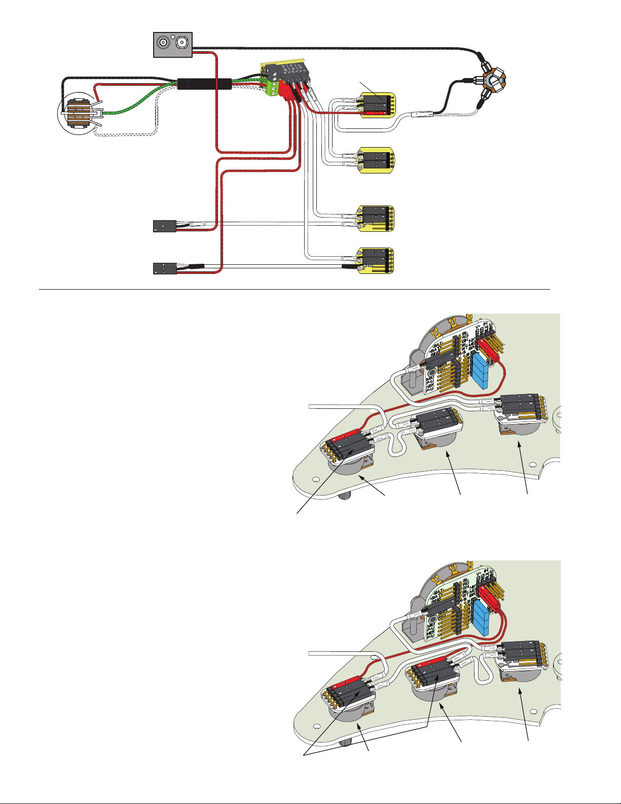
3 Pickup Guitars using a selection switch:
Diagrams #6, #7 show a typical installation with a Volume/Tone/AB 220 in a
“daisy-chain” series wiring. The only difference between the the diagrams
is the order in which the controls are wired. The diagrams yield the same
results. The diagrams have been edited to show the boost input, output,
and power (9V+). The pickup inputs, battery, and “ring”contact to the jack
have been omitted for clarity.
All diagrams show the B161 5-Position switch buss. To learn more
about the B161 5-Position switch Buss, go to the EMG Website:
http://www.emgpickups.com.
Refer to Diagram #6
Start by installing the AB 220 as shown in Diagram #6.
1) Plug a coax cable from the output switch to the Volume control.
2) Plug a coax cable from the Volume control to the Tone control.
3) Plug a coax cable from the Tone control to the input of the SPC.
Be sure to reverse the connector on the input of the 220 as shown.
4) Plug the output cable from the 220 to the output jack.
5) Plug the Red wire from the 220 to one of the supply pins on the
B161 Switch Buss.
Be sure the 3 shunts are installed on the bypass header of the
B161 switch or you won’t get any output from the guitar.
Refer to Diagram #7
Diagram #7 shows 2 active controls installed: AB 220 and VLPF. This is
the same as the X Series Pickups that use an active tone (VLPF)
and adding the AB 220 Control.
Start by installing the AB 220 as shown in Diagram #8.
1) Plug a coax cable from the output switch to the Volume control.
2) Plug a coax cable from the Volume control to the input of the VLPF.
Be sure to reverse the connector on the input of the VLPF as shown.
3) Plug a coax cable from the output of the VLPF to the input of the 220.
Be sure to reverse the connector on the input of the 220 as shown.
4) Plug the output cable from the 220 to the output jack.
5) Plug the Red wires from both the VLPF and 220 to the extra 9V+
supply pins on the B161 Switch Buss.
Be sure the 3 shunts are installed on the bypass header of the
B161 switch or you won’t get any output from the guitar.
VOLUME CONTROL
Diagram #7
Volume Control
Tone (Active VLPF)
AB 220 Control
TONE CONTROL
(ACTIVE VLPF)
AB 220
CONTROL
OUTPUT TO JACK
NOTE:
REVERSED CONNECTOR
NOTE:
REVERSED CONNECTORS
Diagram #5
2 Pickups
Toggle Style Switch
Volume each Pickup (Volumes are independent)
Master Tone (Passive)
AB 220 Control
NOTE:
REVERSED CONNECTOR
AB 220

Other EMG Accessories For Musical Instruments manuals

EMG X Series Service manual

EMG

EMG X Series Service manual

EMG LJV-HZ-EP5 User manual

EMG

EMG LJV-HZ-EP5 User manual

EMG Pro KH-21 Series Service manual

EMG

EMG Pro KH-21 Series Service manual

EMG Pi2 User manual

EMG

EMG Pi2 User manual

EMG X Series Service manual

EMG

EMG X Series Service manual

EMG NECK 89R User manual

EMG

EMG NECK 89R User manual

EMG X Series Service manual

EMG

EMG X Series Service manual

EMG Pso VG-20 Series Service manual

EMG

EMG Pso VG-20 Series Service manual

EMG SA/SA/85 Set Service manual

EMG

EMG SA/SA/85 Set Service manual

EMG EXB Service manual

EMG

EMG EXB Service manual

EMG ALX SET Service manual

EMG

EMG ALX SET Service manual

EMG B136RE Service manual

EMG

EMG B136RE Service manual

EMG EXG Service manual

EMG

EMG EXG Service manual

EMG 40P5-X User manual

EMG

EMG 40P5-X User manual

EMG EMG-707 User manual

EMG

EMG EMG-707 User manual

EMG 35-TW Service manual

EMG

EMG 35-TW Service manual

EMG 60-8X Service manual

EMG

EMG 60-8X Service manual

EMG 81 Service manual

EMG

EMG 81 Service manual

EMG 40-TW Service manual

EMG

EMG 40-TW Service manual

EMG FLAT 6 MEDIUM Service manual

EMG

EMG FLAT 6 MEDIUM Service manual

EMG RETROACTIVE STRAT RA-5 Service manual

EMG

EMG RETROACTIVE STRAT RA-5 Service manual

EMG P-HZ Service manual

EMG

EMG P-HZ Service manual

EMG X Series Service manual

EMG

EMG X Series Service manual

EMG JMASTER Service manual

EMG

EMG JMASTER Service manual

Popular Accessories For Musical Instruments manuals by other brands

Schatten Design TC installation instructions

Schatten Design

Schatten Design TC installation instructions

Fishman NEO-BUSTER PRO-NEO-FB2 user guide

Fishman

Fishman NEO-BUSTER PRO-NEO-FB2 user guide

Kinman Tele install guide

Kinman

Kinman Tele install guide

Kaman Gibraltar 6600 Series Setup instructions

Kaman

Kaman Gibraltar 6600 Series Setup instructions

ILITCH ELECTRONICS LCNCS-H User manual and installation instructions

ILITCH ELECTRONICS

ILITCH ELECTRONICS LCNCS-H User manual and installation instructions

BassLines SPB-1 Wiring diagram

BassLines

BassLines SPB-1 Wiring diagram

Duncan Jimi Hendrix Signature Loaded Pickguard Wiring diagram

Duncan

Duncan Jimi Hendrix Signature Loaded Pickguard Wiring diagram

Konig & Meyer 12384 manual

Konig & Meyer

Konig & Meyer 12384 manual

Turnstyle T2 manual

Turnstyle

Turnstyle T2 manual

Behringer V-Tone Guitar GDI21 manual

Behringer

Behringer V-Tone Guitar GDI21 manual

GRAVITY KSX 2 RD instructions

GRAVITY

GRAVITY KSX 2 RD instructions

Highlander iP-1 manual

Highlander

Highlander iP-1 manual

Qtx 172.993 instruction manual

Qtx

Qtx 172.993 instruction manual

Pickup LesLee Gibson SG installation manual

Pickup LesLee

Pickup LesLee Gibson SG installation manual

K&K Sound PURE 12-STRING quick guide

K&K Sound

K&K Sound PURE 12-STRING quick guide

Zoom RFX-2000 quick start guide

Zoom

Zoom RFX-2000 quick start guide

Highlander iP-2 manual

Highlander

Highlander iP-2 manual

Kinman Jazzmaster Hx install guide

Kinman

Kinman Jazzmaster Hx install guide

manuals.online logo
manuals.online logoBrands
  • About & Mission
  • Contact us
  • Privacy Policy
  • Terms and Conditions

Copyright 2025 Manuals.Online. All Rights Reserved.