Thames & Kosmos Ultra Bionic Blaster User manual

EXPERIMENT MANUAL
620502-03-140522
Ultra
Bionic
Blaster
Franckh-Kosmos Verlags-GmbH & Co. KG, Pfizerstr. 5-7, 70184 Stuttgart, Germany | +49 (0) 711 2191-0 | www.kosmos.de
Thames & Kosmos, 89 Ship St., Providence, RI, 02903, USA | 1-800-587-2872 | www.thamesandkosmos.com
Thames & Kosmos UK LP, 20 Stone Street, Cranbrook, Kent, TN17 3HE, UK | 01580 713000 | www.thamesandkosmos.co.uk
Do you have any
questions?
Our technical support
team will be glad to
help you!
Thames & Kosmos US
Email: support@thamesandkosmos.com
Web: thamesandkosmos.com
Phone: 1-800-587-2872
Thames & Kosmos UK
Web: thamesandkosmos.co.uk
Phone: 01580 713000
2nd Edition © 2022 Thames & Kosmos, LLC, Providence, RI, USA
Thames & Kosmos® is a registered trademark of Thames & Kosmos, LLC.
This work, including all its parts, is copyright protected. Any use outside the specific lim-
its of the copyright law is prohibited and punishable by law without the consent of the
publisher. This applies specifically to reproductions, translations, microfilming, and stor-
age and processing in electronic systems and networks. We do not guarantee that all ma-
terial in this work is free from other copyright or other protection.
Text and Editing: Hannah Mintz, Ted McGuire
Technical product development: Ted McGuire; Genius Toys Taiwan Co., Ltd
Manual illustrations: Genius Toys Taiwan Co., Ltd
Manual photos: Jaimie Duplass & beror (all adhesive strips, ©fotolia), Vector Memory
(gears, ©Shutterstock)
Packaging design and layout: Dan Frietas
Packaging photos: Genius Toys Taiwan Co., Ltd
The publisher has made every effort to identify the owners of the rights to all photos used.
If there is any instance in which the owners of the rights to any pictures have not been ac-
knowledged, they are asked to inform the publisher about their copyright ownership so
that they may receive the customary image fee.
Distributed in North America by Thames & Kosmos, LLC. Providence, RI 02903
Phone: 800-587-2872; Web: www.thamesandkosmos.com
Distributed in United Kingdom by Thames & Kosmos UK LP. Cranbrook, Kent TN17 3HE
Phone: 01580 713000; Web: www.thamesandkosmos.co.uk
We reserve the right to make technical changes.
Printed in Taiwan / Imprimé en Taiwan
I
--
Scan ths QR code
for a step-by-step
assembly vdeo and
manual gude

KIT CONTENTS
What’s inside your experiment kit:
Do you have any questions or are you
missing any parts? Our tech support
team will be happy to help you!
or 1-800-587-2872
Good to know!
21x
R
C
G
F
E
D
A1
A2
A3
A4
A5
A6
A7
A8
B7
B8
B9
A9
A10
A11
A12
A13
A14
A15
A16
B10
B11
B12
B13
B14
B15
B16
B17
A17
A18
B1
B2
B3
B4
B5
B6
L
Scan ths QR code to see awesome
experments you can do wth your
Ultra Bonc Blaster
Plus learn
about
pneumatics
and devces
that use air
to perform
work
A3
A7
Pull the front
handle will unlock
the shooting
platform. Once the
trigger is pressed,
the platform will
automatically rise
up.
HOW TO ADD THE RESERVE CLIP
When you are happy with the position of
the arm band, add the reserve clip (A3). The reserve clip allows you to carry
three extra darts.
HOW TO LIFT THE LAUNCH PLATFORM
Pull out the green handle under
the front cover (C5) to put the
blaster in auto lift mode.
Push the green handle back, and
the launch platform will be
locked in the lower position.
In this mode, the launch platform will lift when
you pull the trigger for the first time. After that,
it will launch a dart when you pull the trigger.
In this mode, the launch platform will not lift
when you pull the trigger.
HOW TO LAUNCH DARTS
Squeeze the green trigger with your hand.
AUTO
LIFT
MODE
LOCKED
MODE
click
click

The right tool
It s best to cut the plastc parts out of ther
frames wth a small dagonal cutter
If you don’t have these plers at home, you can
use scssors and a nal fle Normal scssors
do not cut as precsely as a dagonal cutter, so
you may have to fle some of the rough edges
down wth the nal fle
Checklist:
No Descrpton Quantty Item No
Frame wth parts 1-6 1 7080-W10-1S
D Frame D wth parts D1-D7 1 7080-W10-D1P
E Frame E wth parts E1-E21 1 7080-W10-E1
F Frame F wth parts F1-F8 1 7080-W10-F1S
Frame wth parts 1-6 1 7080-W10-1S
A1 Tube 1 1155-W85-17
A2 Arm aduster 1 7080-W10-K5S
A3 Reserve clp 1 7080-W10-H4S
A4 ylnder support 1 7080-W10-B1S
A5 Arm band 1 R33#7080
A6 Dart holder 3 7080-W10-I1S
A7 Dart 6 R32#7080-2
A8 Ol packet 1 T10-41
A9 Blaster frame 1 7080-W10-A1S
A10 Outer cylnder 1 7080-W10-J1S
A11 Rear nozzle 1 7080-W10-J2S
A12 ylnder housng 1 7080-W10-J3S
A13 Pston cap 1 7080-W10-J4S
A14 Pston sleeve 1 7080-W10-J5S
A15 Pston base 1 7080-W10-K1S
No Descrpton Quantty Item No
A16 Pston hook 1 7080-W10-K2S
A17 Pston rod 1 7080-W10-K3S
A18 Ar wheel 1 7080-W10-K4S
B1 Outer lft support 2 7080-W10-B4S
B2 Handle 1 7080-W10-H3S
B3 Inner lft support 2 7080-W10-B3S
B4 Axle connector 1 7413-W10-T1B
B5 Blaster fxture (left) 1 7080-W10-H1S
B6 Blaster fxture (rght) 1 7080-W10-H2S
B7 ylnder pvot 1 7080-W10-B2S
B8 Sprng wth loops 1 M42-41
B9 Small sprng 1 M42-39
B10 Medum sprng 3 M42-40
B11 Large sprng 1 M42-38-1
B12 Foam pad 1 R32#7080-1
B13 Screw 21 M20-44
B14 Metal rod 2 M10#1155
B15 Small O-rng 1 R12-19
B16 Medum O-rng 1 R12-30
B17 Large O-rng 1 R12-29
1
Ultra Bionic Blaster
TABLE OF CONTENTS
Kit Contents .............................................. Inside front cover
Table of Contents, Safety Information, & Introduction............1
ASSEMBLY STARTS ON PAGE 2
Ultra Bionic Blaster Assembly ..................................... 2
Testing the cylinder .................................................... 6
Operating Instructions ...............................................20
Experiments & Science Info. ................ Inside back cover
Diagonal cutter or scissors and nail file, small
Philips-head screwdriver (PH1 size
recommended), device with internet connection
for the experiments and additional science info.
620502-02-300622
Not suitable for children under 3 years.
Choking hazard — small parts may be
swallowed or inhaled. Strangulation
hazard — long tubes and belts may
become wrapped around the neck.
Keep the packaging and instructions as
they contain important information.
Warning! Do not discharge an object
other than the projectile provided with
this toy.
Warning! Do not aim at eyes or face.
Use of eyewear recommended for
players and people within range.
Do not modify the darts.
!
!
WARNING
Children as young as eight
years of age can enjoy
experimenting with the built
Ultra Bionic Blaster, but
most children under ten
years will need help building
it. Please support your child
with advice and a helping
hand, especially during
tricky assembly steps.
Before beginning, discuss
the safety instructions.
Take special care when
cutting the plastic parts out
of the frames with the
diagonal cutters or scissors
because of the sharp edges
on the tools and sharp edges
or burrs on the plastic parts.
These can be removed with
the help of the diagonal
cutters or a nail file.
Supervise your child when
they are using the sharp
tools until you trust that they
can handle the tools
independently.
We hope you and your
child have a lot of fun
building and playing with the
Ultra Bionic Blaster!
Dear parents
and adults,
You will also need:

11
7
89
10
B
C
RR
L
L
L
L
Put in flat.
6Note: C3 is labeled with an R.
Note: C1 is labeled with an L.
C1
C3
G1
E2
E11
E14
E15
x2
B13
B13
x2
1
2
Move the green
slider back and
forth. The movement
should be smooth.
1
3
2
2
1
2
3
4
5
A
R
Orient parts E12 and G3 so that
both of the R letters are face up.
Put in flat.
Flip over.
G4
G6
E2
E8
R
R
G3
E12
E14
E15
E17
E18
x3
B13
B10
Slide E17 and E18 into
the slots of G6.
The orientation of
E14 does not matter.
medium
spring
1
L
The teeth of E8 face down.
This is subassembly A.
Squeeze the trigger.
It should spring back
smoothly.
3
Apply oil all around the teeth of E12, as
shown by the yellow arrows. Only a small
amount of oil is needed; the oil should not
be dripping off the part.
E12
Oil
1 2
E20
E21
A8
Pour all
of the oil
into E21.
3
4
Important!
REMOVE ALL BURRS
FROM THE PARTS AFTER CUTTING THEM OUT OF
THE FRAMES with diagonal cutters.
If you do not
have diagonal
cutters, use
scissors and a
nail le.
Burr
Burr
ULTRA BIONIC BLASTER ASSEMBLY
2

11
7
89
10
B
C
RR
L
L
L
L
Put in flat.
6Note: C3 is labeled with an R.
Note: C1 is labeled with an L.
C1
C3
G1
E2
E11
E14
E15
x2
B13
B13
x2
1
2
Move the green
slider back and
forth. The movement
should be smooth.
1
3
2
2
1
2
3
4
5
A
R
Orient parts E12 and G3 so that
both of the R letters are face up.
Put in flat.
Flip over.
G4
G6
E2
E8
R
R
G3
E12
E14
E15
E17
E18
x3
B13
B10
Slide E17 and E18 into
the slots of G6.
The orientation of
E14 does not matter.
medium
spring
1
L
The teeth of E8 face down.
This is subassembly A.
Squeeze the trigger.
It should spring back
smoothly.
3
Apply oil all around the teeth of E12, as
shown by the yellow arrows. Only a small
amount of oil is needed; the oil should not
be dripping off the part.
E12
Oil
1 2
E20
E21
A8
Pour all
of the oil
into E21.
3
4
1. Apply a small amount of oil to
the teeth of E11.
2. Orient parts E11 and G1 so that
both of the L letters are face up.
Remove burrs!
Move the green
slider back and
forth. The movement
should be smooth.
3
Assembling the Ultra Bionic Blaster

12 13 14
15 16
17
18 19
D
E
click
3
12
1
2
3
Top view Bottom view
Press the metal
rod through the
holes as shown.
Make sure the
sticky side faces up.
Assemble in order. Press
A13 in all
the way.
Compress the spring
with A16 and align the
holes of A16 and A17.
Pull A16 back with your
finger. It should spring
back.
Press A14 all the way down
until you hear a click.
Apply oil to the
outside of the
O-ring.
Apply oil all
around the
groove of A15
as shown.
A13
A14
A15
A16
A17
B9
B12
B14
B17
large O-ring
A16
B14
A15
small
spring A16 is very
small. If you
can’t find it,
look inside
of the other
parts in the
bag.
The two tabs
of A13 fit into
the slots of
A15.
!
20 21
22 23
24
25
26
D
E
12
IMPORTANT!
Make sure this
hole faces up.
Press down so that
A16 hooks around the
metal rod.
Press subassembly D
all the way in, aligning
the four notches into
the grooves of A10.
This tab slides
into the slot.
1. Apply oil to the
groove as shown.
2. Add the medium
O-ring.
1. Apply oil to A18 as shown.
2. Place the small O-ring
onto A18.
3. Place A18 as shown.
Apply oil to
the O-ring.
Apply oil and place
the small O-ring in
the indent around
the open hole in A18.
A10
A12
B11
B15
B16 small O-ring
Make sure the
flat sides of
A10 face up.
A16
x4
B13
1. Add the large spring (B11).
2. Slide A12 all the way in.
Flip over.
medium O-ring
1
21
2
A18
3
large spring
Hold A12
down as
you secure
it with four
screws.
Pull up on
subassembly E to
make sure that it
is securely
attached to
subassembly D. It
should not come
off.
4

12 13 14
15 16
17
18 19
D
E
click
3
12
1
2
3
Top view Bottom view
Press the metal
rod through the
holes as shown.
Make sure the
sticky side faces up.
Assemble in order. Press
A13 in all
the way.
Compress the spring
with A16 and align the
holes of A16 and A17.
Pull A16 back with your
finger. It should spring
back.
Press A14 all the way down
until you hear a click.
Apply oil to the
outside of the
O-ring.
Apply oil all
around the
groove of A15
as shown.
A13
A14
A15
A16
A17
B9
B12
B14
B17
large O-ring
A16
B14
A15
small
spring A16 is very
small. If you
can’t find it,
look inside
of the other
parts in the
bag.
The two tabs
of A13 fit into
the slots of
A15.
!
20 21
22 23
24
25
26
D
E
12
IMPORTANT!
Make sure this
hole faces up.
Press down so that
A16 hooks around the
metal rod.
Press subassembly D
all the way in, aligning
the four notches into
the grooves of A10.
This tab slides
into the slot.
1. Apply oil to the
groove as shown.
2. Add the medium
O-ring.
1. Apply oil to A18 as shown.
2. Place the small O-ring
onto A18.
3. Place A18 as shown.
Apply oil to
the O-ring.
Apply oil and place
the small O-ring in
the indent around
the open hole in A18.
A10
A12
B11
B15
B16 small O-ring
Make sure the
flat sides of
A10 face up.
A16
x4
B13
1. Add the large spring (B11).
2. Slide A12 all the way in.
Flip over.
medium O-ring
1
21
2
A18
3
large spring
Hold A12
down as
you secure
it with four
screws.
Pull up on
subassembly E to
make sure that it
is securely
attached to
subassembly D. It
should not come
off.
5
Assembling the Ultra Bionic Blaster

27 28
30
29
Perform cylinder tests
A and B before
continuing to step 31.
Line up the
opening in
A11 with
this line.
Apply oil to
the O-ring.
A11 x4
B13
STOP
Push down on
the lever ...
... to lift up the
piston rod.
Then release
the piston.
2
3
1
x2
Secure
A11 with
four
screws.
AMake sure the piston rod has been installed correctly.
1. Insert E4 into the hole of the piston rod.
2. Place the two forks of the lever tool (E10)
under E4 on either side of the piston rod.
3. Push down on the lever to lift up the
piston rod, then release. Repeat two
times.
E4
E10
As you do this, observe the piston rod from the side:
If the piston rod
can be lifted up
easily and retracts
automatically,
move on to test B.
The piston rod does not move when
you try to lift it.
Go back to steps 21–23, and make
sure all parts have been installed
correctly. Or watch the demo video.
1This is the correct position of the
air wheel. Repeat steps 1 and 2
until it looks like this.
Then proceed to step 31.
31 32
33
34
F
G
click
Press all the way down,
aligning the grooves.
Use a screwdriver or other
tool to press E14 down until
you hear a click.
1. Confirm the orientation
of E6, then press into B7
until you hear a click.
F6 E5
E6
D1
D2
B7
B10
E14
E14
click
Turn upside down to
ensure that the E14
parts do not fall out.
medium
spring
E6
E5
click
click
1
2
2. Confirm the orientation
of E5, then press into B7
until you hear a click.
H
2
BMake sure the air wheel (A18) is in the correct position.
B7
2. Slide the notch of
B7 along the
groove as shown.
1. Place the notch of B7
all the way into the
groove of the cylinder.
A11
CYLINDER TEST
demo!
Scan this QR code
for a video
showing how to
test the cylinder.
6

27 28
30
29
Perform cylinder tests
A and B before
continuing to step 31.
Line up the
opening in
A11 with
this line.
Apply oil to
the O-ring.
A11 x4
B13
STOP
Push down on
the lever ...
... to lift up the
piston rod.
Then release
the piston.
2
3
1
x2
Secure
A11 with
four
screws.
AMake sure the piston rod has been installed correctly.
1. Insert E4 into the hole of the piston rod.
2. Place the two forks of the lever tool (E10)
under E4 on either side of the piston rod.
3. Push down on the lever to lift up the
piston rod, then release. Repeat two
times.
E4
E10
As you do this, observe the piston rod from the side:
If the piston rod
can be lifted up
easily and retracts
automatically,
move on to test B.
The piston rod does not move when
you try to lift it.
Go back to steps 21–23, and make
sure all parts have been installed
correctly. Or watch the demo video.
1This is the correct position of the
air wheel. Repeat steps 1 and 2
until it looks like this.
Then proceed to step 31.
31 32
33
34
F
G
click
Press all the way down,
aligning the grooves.
Use a screwdriver or other
tool to press E14 down until
you hear a click.
1. Confirm the orientation
of E6, then press into B7
until you hear a click.
F6 E5
E6
D1
D2
B7
B10
E14
E14
click
Turn upside down to
ensure that the E14
parts do not fall out.
medium
spring
E6
E5
click
click
1
2
2. Confirm the orientation
of E5, then press into B7
until you hear a click.
H
2
BMake sure the air wheel (A18) is in the correct position.
B7
2. Slide the notch of
B7 along the
groove as shown.
1. Place the notch of B7
all the way into the
groove of the cylinder.
A11
7
Assembling the Ultra Bionic Blaster

1
2
35 36
38
39
40
II
I
I
J
37 x3
x3
x3 x3
click
Rotate the E13 parts
90° to lock.
Make sure to insert
G5 parallel to G2.
Side view
Align the three lines.
Press all the way down
until you hear a click.
G2
G5
F7
E13
E16
D7 D7
D6
D6
A6
Note the difference
between the parts:
C6
F8
Rotate the green dial
180° clockwise. The
cylinders should
spread open.
41 42 43
44 45
4746
K
L
1
2
Make sure
the fuzzy side
faces out.
Place one loop of the spring
(B8) over the small peg on B1.
Notice the
spring is on
the right side
of the X shape.
Fold over the strap so
that the rough side
sticks to the fuzzy side.
D3
D3
D4
D5
A2
A5
B1
B1
B3
B3 B4
B8
B12
x2
The two half circles
fit together.
The two half circles
fit together.
The small pegs on
B1 lock together
inside the loop of
the spring.
!
IMPORTANT!
Do not cut the
tabs off of the
D3 parts. They
are not burrs.
8

1
2
35 36
38
39
40
II
I
I
J
37 x3
x3
x3 x3
click
Rotate the E13 parts
90° to lock.
Make sure to insert
G5 parallel to G2.
Side view
Align the three lines.
Press all the way down
until you hear a click.
G2
G5
F7
E13
E16
D7 D7
D6
D6
A6
Note the difference
between the parts:
C6
F8
Rotate the green dial
180° clockwise. The
cylinders should
spread open.
41 42 43
44 45
4746
K
L
1
2
Make sure
the fuzzy side
faces out.
Place one loop of the spring
(B8) over the small peg on B1.
Notice the
spring is on
the right side
of the X shape.
Fold over the strap so
that the rough side
sticks to the fuzzy side.
D3
D3
D4
D5
A2
A5
B1
B1
B3
B3 B4
B8
B12
x2
The two half circles
fit together.
The two half circles
fit together.
The small pegs on
B1 lock together
inside the loop of
the spring.
!
IMPORTANT!
Do not cut the
tabs off of the
D3 parts. They
are not burrs.
9
Assembling the Ultra Bionic Blaster

48
49 50
51 H
K
L2
3
flat side
Flat side
notched
side
Notched
side
3. Place the
other loop of
the spring
(B8) over the
hook on the
bottom of A9.
1. Place subassembly L into
A9 as shown.
Place A4 as shown. Pay
attention to the orientation.
1. Slide both green sliders on
subassembly H up into the
locked position.
2. Install subassembly H, paying
attention to the orientation of the
parts.
F3
F4
Before After
A4
A9
Push the lower sections of both purple
parts inwards as you slide subassembly K
onto the blaster frame.
Flip over.
2. Slide it back to
lock it in place.
push in
push in
notched side
H
1
1
2
flat
side
Side view
Press all
the way in.
52
53
F
54
1
2
Press subassembly F all the way in
until you hear a click. The cylinder
will lock automatically.
Hold the assembly in your hand while
you place subassembly F.
Unlock both green sliders.
The cylinder will spring back.
Before After
click
The cylinder will
spring back into place.
10

48
49 50
51 H
K
L2
3
flat side
Flat side
notched
side
Notched
side
3. Place the
other loop of
the spring
(B8) over the
hook on the
bottom of A9.
1. Place subassembly L into
A9 as shown.
Place A4 as shown. Pay
attention to the orientation.
1. Slide both green sliders on
subassembly H up into the
locked position.
2. Install subassembly H, paying
attention to the orientation of the
parts.
F3
F4
Before After
A4
A9
Push the lower sections of both purple
parts inwards as you slide subassembly K
onto the blaster frame.
Flip over.
2. Slide it back to
lock it in place.
push in
push in
notched side
H
1
1
2
flat
side
Side view
Press all
the way in.
52
53
F
54
1
2
Press subassembly F all the way in
until you hear a click. The cylinder
will lock automatically.
Hold the assembly in your hand while
you place subassembly F.
Unlock both green sliders.
The cylinder will spring back.
Before After
click
The cylinder will
spring back into place.
11
Assembling the Ultra Bionic Blaster
I
Check out the
assembly video to
see how to install
the cylinder:

56
57
58
55
click
R
L
1
1
2
2
12
Slide back until you
hear a click.
1. Notice there are
R (right) and L (left)
letters on the parts.
Press E4 all the
way in.
F5
E3
E3
E4
E9
B5
B6
2. Press all the way in
until you hear a click.
You may need to push
the piston rod in so that
the holes lines up.
Top view
click
click
Press E3 all the
way onto E9.
Rotate
subassembly B so
that the light gray
side faces out.
1
1
2
2
3
4
59
60
R
R
R
B
B
Side view
Side view
Turn the axle so that the
line in the center is
vertical and aligned as
shown.
Place the gear E1 so that the
line is on the bottom, vertical,
and aligned as shown.
1. Push the slider all the
way down.
2. Place subassembly B.
3. Place C4.
4. Rotate C4 clockwise to
lock.
Rotate the cap
clockwise to lock.
C4
E1
R
Align gears exactly as shown.
Remove
burrs!
12

56
57
58
55
click
R
L
1
1
2
2
12
Slide back until you
hear a click.
1. Notice there are
R (right) and L (left)
letters on the parts.
Press E4 all the
way in.
F5
E3
E3
E4
E9
B5
B6
2. Press all the way in
until you hear a click.
You may need to push
the piston rod in so that
the holes lines up.
Top view
click
click
Press E3 all the
way onto E9.
Rotate
subassembly B so
that the light gray
side faces out.
1
1
2
2
3
4
59
60
R
R
R
B
B
Side view
Side view
Turn the axle so that the
line in the center is
vertical and aligned as
shown.
Place the gear E1 so that the
line is on the bottom, vertical,
and aligned as shown.
1. Push the slider all the
way down.
2. Place subassembly B.
3. Place C4.
4. Rotate C4 clockwise to
lock.
Rotate the cap
clockwise to lock.
C4
E1
R
Align gears exactly as shown.
13
Assembling the Ultra Bionic Blaster

Rotate subassembly C so that
the light gray side faces out.
1
2
61
62
63
A
CC
R
R
L
L
L
2
3
4
1
3
Side view
Side view
Align gears exactly as shown.
Rotate the cap
counterclockwise
to lock.
C4
E1
Fasten, but do not tighten
the screws all the way.
B13 x3
Turn the axle to so that
the line in the center is
vertical and aligned as
shown.
Place the gear E1 so that the line is on the bottom,
vertical, and aligned as shown.
1. Push the slider all
the way down.
2. Place subassembly C.
3. Place C4.
4. Rotate C4 counter-
clockwise to lock.
1
E8
Make sure E8 is
pulled out all the way
while assembling.
1
2
Apply oil to the teeth of
subassembly A on both sides.
64
65
66
2
3
Front view
The slots on
the bottom
of E7 slide
along
these
tracks.
1. Apply oil to the top and bottom of the
two E7 parts as shown.
2. Slide the tracks (E7) all the way in
(see image below).
3. Then place the tracks down so that
their teeth mesh with the gears below.
Place the
neck of E19
into the
semi-circular
notch as
shown.
E19
Fasten, but do not
tighten the screws
all the way.
B13 x3
E7
E7
1E7
Top
Bottom
Make sure there is no gap
at all between E7 and the
purple rail on both sides.
Even a small gap here will
cause a malfunction.
!
IMPORTANT!
Make sure the
green sliders are
pushed down and
the trigger is
pulled out.
14

Rotate subassembly C so that
the light gray side faces out.
1
2
61
62
63
A
CC
R
R
L
L
L
2
3
4
1
3
Side view
Side view
Align gears exactly as shown.
Rotate the cap
counterclockwise
to lock.
C4
E1
Fasten, but do not tighten
the screws all the way.
B13 x3
Turn the axle to so that
the line in the center is
vertical and aligned as
shown.
Place the gear E1 so that the line is on the bottom,
vertical, and aligned as shown.
1. Push the slider all
the way down.
2. Place subassembly C.
3. Place C4.
4. Rotate C4 counter-
clockwise to lock.
1
E8
Make sure E8 is
pulled out all the way
while assembling.
1
2
Apply oil to the teeth of
subassembly A on both sides.
64
65
66
2
3
Front view
The slots on
the bottom
of E7 slide
along
these
tracks.
1. Apply oil to the top and bottom of the
two E7 parts as shown.
2. Slide the tracks (E7) all the way in
(see image below).
3. Then place the tracks down so that
their teeth mesh with the gears below.
Place the
neck of E19
into the
semi-circular
notch as
shown.
E19
Fasten, but do not
tighten the screws
all the way.
B13 x3
E7
E7
1E7
Top
Bottom
Make sure there is no gap
at all between E7 and the
purple rail on both sides.
Even a small gap here will
cause a malfunction.
!
IMPORTANT!
Make sure the
green sliders are
pushed down and
the trigger is
pulled out.
15
Assembling the Ultra Bionic Blaster
After installing subassemblies A, B, and C,
test the trigger.
> When the trigger is at rest, both green
sliders should be all the way down, and
there should be no gap between the
trigger and the handle.
> Now squeeze the trigger. The motion
should be smooth, and the trigger should
spring back easily.
If you have problems with any
of these checks, go back to
step 57 or watch this video:

67
68
69
G
click
1
RL
1
2
3
3. Slide C5 all the way back
until you hear a click.
1. Place subassembly G,
making sure to align the
grooves as shown.
C5
F1
F2
Before
Side view
Side view
After
2. To lock in place, slide back
until you hear a click.
2
Notice there are R (right) and
L (left) letters on the parts.
1. Press down on the platform.
2. Place the hooks of C5 into the slots
as shown.
click
70
71
72
J
click
1
3
2
1
2
Press B2 down until you hear
a click.
3. Use both hands to push subassembly
J back until you hear a click.
1. Line up all six holes of C2 as
shown and press down.
2. Slide C2 back to lock in place.
1. Line up the three holes on the right
side of subassembly J as shown.
2. Line up the other three holes and
press down all the way.
C2
B2
click
click
16

67
68
69
G
click
1
RL
1
2
3
3. Slide C5 all the way back
until you hear a click.
1. Place subassembly G,
making sure to align the
grooves as shown.
C5
F1
F2
Before
Side view
Side view
After
2. To lock in place, slide back
until you hear a click.
2
Notice there are R (right) and
L (left) letters on the parts.
1. Press down on the platform.
2. Place the hooks of C5 into the slots
as shown.
click
70
71
72
J
click
1
3
2
1
2
Press B2 down until you hear
a click.
3. Use both hands to push subassembly
J back until you hear a click.
1. Line up all six holes of C2 as
shown and press down.
2. Slide C2 back to lock in place.
1. Line up the three holes on the right
side of subassembly J as shown.
2. Line up the other three holes and
press down all the way.
C2
B2
click
click
17
Assembling the Ultra Bionic Blaster

73
74
75
25 cm
28.5 cm
Use the ruler above to
cut two pieces of tube
to a length of 25 cm,
and one piece of tube
to 28.5 cm.
1. Place one end of a 25-cm tube on the
right-most nozzle.
2. Clip the tube into the right most clip.
3. Place the other end of the tube on
the top right nozzle at the back of the
blaster.
A1 25 cm x2 28.5 cm x1
1. Place one end of the 28.5-cm tube on
the middle nozzle.
2. Clip the tube into the middle clip.
3. Place the other end of the tube on
the bottom nozzle at the back of the
blaster.
1
2
2
Connect the tube
to the top right
nozzle in the back.
3
3
2
2
Connect the tube
to the bottom
nozzle in the back.
3
3
1
You have finished
assembling the
blaster!
Now it’s time to test it out and
troubleshoot any issues.
Turn to page 20
76
25 cm
77
2.5 cm
~1 inch
Leave about 2.5 cm
(1 inch) of space for the
tube as shown.
The air tube
should not be
bent like this.
It will affect the
power of the
blaster.
1. Place one end of the other 25-cm tube
on the left-most nozzle.
2. Clip the tube into the left-most clip.
3. Place the other end of the tube on the
top left nozzle at the back of the blaster.
Connect the tube
to the top left
nozzle in the back.
1
2
2
3
3
12 13 14
15 16 17 18 19 20 21 22 23 24 25
cm
1 2 3 4 5 6 7 8 9 10 11 120
26 27 28 29
Start
18
Other manuals for Ultra Bionic Blaster
1
Other Thames & Kosmos Robotics manuals

Thames & Kosmos
Thames & Kosmos Robotics Smart Machines User manual

Thames & Kosmos
Thames & Kosmos SUPERSPHERE User manual

Thames & Kosmos
Thames & Kosmos WindBots 6-IN-1 WIND-POWERED MACHINE KIT User manual
Thames & Kosmos
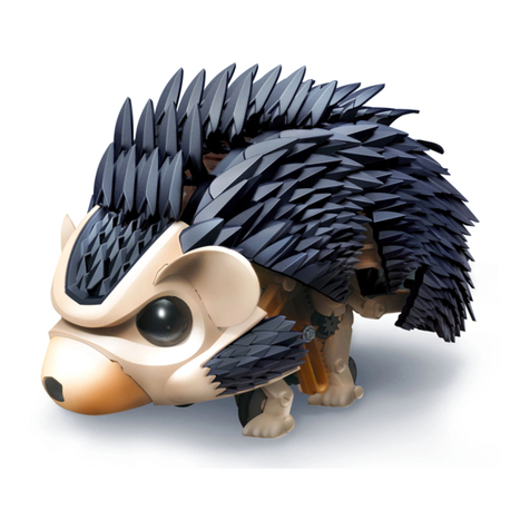
Thames & Kosmos TUMBLING HEDGEHOG User manual

Thames & Kosmos
Thames & Kosmos SolarBots User manual

Thames & Kosmos
Thames & Kosmos SpringBots User manual

Thames & Kosmos
Thames & Kosmos SIDEKICK User manual
