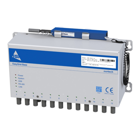
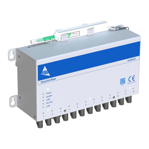
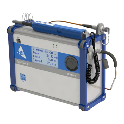
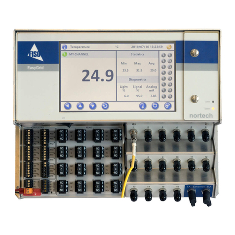
Fiso Nortech EasyGrid LT User manual

EasyGrid LT User Guide
EasyGrid LT
(EGD-LT)
User Guide
MAN-00095

EasyGrid LT User Guide
ii
All rights reserved. No part of this publi ation may be reprodu ed, stored in a retrieval system, or
transmitted in any form, be it ele troni ally, me hani ally, or by any other means su h as photo opying,
re ording, or otherwise, without the prior written permission of FISO.
Information provided by FISO is believed to be a urate and reliable. However, no responsibility is
assumed by FISO for its use or for any infringements of patents or other rights of third parties that may
result from its use. No li ense is granted by impli ation or otherwise under any patent rights of FISO.
FISO’s Commer e and Government Entities (CAGE) ode under the North Atlanti Treaty Organization
(NATO) is L0294.
The information ontained in this publi ation is subje t to hange without noti e.
© 2014 FISO Te hnologies In .
Words that FISO onsiders trademarks have been identified as su h. However, neither the presen e nor
absen e of su h identifi ation affe ts the legal status of any trademark.
Units of measurement in this do ument onform to SI standards and pra ti es
Fiso Technologies Inc.
500, Ave St-Jean-Baptiste, suite 195
Québe (Québe )
G2E 5R9, Canada
Tel : +1 418 688 8065
Fax : +1 418 688 8067
info@fiso. om
www.fiso. om

EasyGrid LT User Guide
iii
1 Table of Content
2 roduct Certification ....................................................................................................................... 1
CE Information ..................................................................................................................................... 1
2.1
Independent Laboratory Testing ........................................................................................................ 1 2.2
De laration of onformity................................................................................................................... 2 2.3
3
Safety Information .......................................................................................................................... 3
Safety Conventions ............................................................................................................................. 3 3.1
Safety Information .............................................................................................................................. 3 3.2
Unpa king and Inspe tion .................................................................................................................. 4 3.3
4
Hardware Configuration .................................................................................................................. 5
Introdu ing the EasyGrid LT................................................................................................................ 5 4.1
Front Panel Overview .......................................................................................................................... 5 4.2
Grounding Terminal ............................................................................................................................ 6 4.3
Powering the EasyGrid LT ................................................................................................................... 6 4.4
Opti al Conne tor ............................................................................................................................... 7 4.5
LCD Display .......................................................................................................................................... 8 4.6
Display Menus Overview .................................................................................................................... 8 4.7
Display Des ription .............................................................................................................................. 9 4.8
Navigation Flow hart ....................................................................................................................... 17 4.9
LED Indi ators .................................................................................................................................... 18 4.10
4.10.1 System Status LED ..................................................................................................................... 18
4.10.2 Communi ation Status LED ...................................................................................................... 18
4.10.3 Relay/Alarm Status LED ............................................................................................................ 19
4.10.4 Sensor Channel Status LED ....................................................................................................... 19
Analog Outputs .................................................................................................................................. 20 4.11
Communi ation Configuration ......................................................................................................... 20 4.12
4.12.1 USB ............................................................................................................................................. 20
4.12.2 RS-485/RS-422 Ports ................................................................................................................. 21
Physi al dimensions .......................................................................................................................... 23 4.13
5
Wiring information ........................................................................................................................ 24
General ............................................................................................................................................... 24 5.1
Power ................................................................................................................................................. 25 5.2
Analog output .................................................................................................................................... 26 5.3
System relay....................................................................................................................................... 27 5.4
RS-422/485 ........................................................................................................................................ 28 5.5
Relays ................................................................................................................................................. 30 5.6
6
Nortech Client Software ................................................................................................................ 31
7
Troubleshooting ............................................................................................................................ 32
Solving Common Problems ............................................................................................................... 32 7.1
Diagnosti s ......................................................................................................................................... 33 7.2
7.2.1 Sensor Light Value..................................................................................................................... 33
7.2.2 Signal .......................................................................................................................................... 33
8
Warranty and Service .................................................................................................................... 34
General Information.......................................................................................................................... 34 8.1
Liability ............................................................................................................................................... 34 8.2

EasyGrid LT User Guide
iv
Ex lusions ........................................................................................................................................... 34 8.3
Certifi ation ....................................................................................................................................... 34 8.4
Transportation ................................................................................................................................... 35 8.5
FISO Servi e Center ........................................................................................................................... 35 8.6
Produ t disposal ................................................................................................................................ 35 8.7

EasyGrid LT User Guide
1
2 roduct Certification
CE Information
2.1
Ele troni test equipment is subje t to the EMC Dire tive in the European
Union. The EN61326 standard pres ribes both emission and immunity
requirements for laboratory, measurement, and ontrol equipment.
This unit has been tested and found to omply with the limits for a Class B
digital devi e. Please refer to the De laration of Conformity.
Independent Laboratory Testing
2.2
This unit has undergone extensive testing a ording to the European Union Dire tive and Standards.
Tests were performed externally, at an independent, a redited laboratory. This guarantees the unerring
obje tivity and authoritative omplian e of all test results.
Use of shielded remote I/O ables, with properly grounded shields and metal onne tors, is
re ommended in order to redu e radio frequen y interferen e that may emanate from these ables.
Shielded I/O ables are re ommended to improve prote tion against lightning surge if unit or ables are
installed in outdoor area. See ertifi ate and tests of omplian e.
EasyGrid LT has been extensively tested to stringent environmental standards to ensure it remains
reliable when used under published spe ifi ations.

EasyGrid LT User Guide
2
Declaration of conformity
2.3
FISO Technologies Inc
.,
located at 500, Saint-Jean-Baptiste Ave., Suite 195, Quebec, QC, Canada G2E 5 9
Product description: Fiber optic thermometer
Model number(s): Eas Grid LT
Product categor :
Electrical equipment for measurement, control and laborator use.
We hereby declare that those products conforms to the provisions of the Electromagnetic Compatibility (EMC) Directive 2004/108/EC, and the
Essential Health and Safety equirement of the Low-Voltage Directive 2006/95/EC
EMC Standards:
CISP 11 : 2009 (ED 5 2010-3)
EN 55011 : 2009 + A1 2010 Measurement of conducted emission Group 1, class A (Industrial)
CISP 11 : 2009 (ED 5 2010-3)
EN 55011 : 2009 + A1 2010
EN 55022 : 2010
Measurement of radiated emission Group 1, class A (Industrial)
IEC 61000-4-2 : 2008
IEC 60255-22-2 : 2008 Electrostatic discharge immunity ±8kV Contact Discharge
±15kV Air Discharge
IEC 61000-4-3 : 2010
IEC 60255-22-3 : 2007 adiated electromagnetic field immunity 10V/m, 80-1000MHz
10V/m, 1.4-2.7GHz
IEC 61000-4-4 : 2008
IEC 60255-22-4 : 2008 Electrical fast transient immunity (EFT) ±4kV Power Lines, ±4kV I/O
IEEE C37.90.1: 2012
Fast Transient Surge Withstand Capability
±4kV Power Lines, ±4kV I/O
IEC 61000-4-5 : 2005
IEC 60255-22-5 : 2008 Surge immunity 2kV Power Line to earth
1kV Power Line to Power line
IEC 61000-4-6 : 2008
IEC 60255-22-6 : 2001 Conducted disturbance induced by F fields 10Vrms
IEC 61000-4-8 : 2009 Power Frequency Magnetic Field immunity 100A/m permanent
1000A/m short duration
IEC 61000-4-9 : 2001 Pulse magnetic field immunity 1000A/m
IEC 61000-4-11 : 2004 Voltage dips, short interruptions and voltage variation
immunity
1 Cycle / 0% 10 Cycles / 40%,
25 Cycles / 70% 250 Cycles / 80%
250 Cycles / 0%,
IEC 60255-5 : 2000
IEC 61180-1 : 1992-10 Impulse voltage withstand test ±5kV
IEC 61000-4-18 : 2011
IEC 60255-22-1 : 2007
IEEE C37.90.1 : 2012
Burst disturbance 2.5kV 2s
IEEE C37.90 : 2005 Dielectric Strength ( S-485 Circuit Only) 4.2kV DC, 4kV AC / 60 Hz
Shock, vibration and transportation:
IEC 60255-21-1 (1988) Vibration: response , endurance Severity Class 2
IEC 60255-21-2 (1988-10) Shock: response, withstand and bump test Severity Class 2
IEC 60255-21-3 (1993-09) Seismic test Severity Class 2
MIL-STD-810G
w/change1, (2014)
Transport vibrations
(Method 514.7)
Category 4

EasyGrid LT User Guide
3
3 Safety Information
Safety Conventions
3.1
Before using the produ t des ribed in this guide, you should understand the following onventions:
DANGER
Indicates a potentially hazardous situation which, if not avoided,
could result in death or serious injury. Do not proceed unless
you understand and meet the required conditions.
WARNING
Indicates a potentially hazardous situation which, if not avoided,
may result in minor or moderate injury. Do not proceed unless
you understand and meet the required conditions.
CAUTION
Indicates a potentially hazardous situation which, if not avoided,
may result in component damage. Do not proceed unless you
understand and meet the required conditions.
IMPORTANT
Refers to information about this product you should not
overlook.
Safety Information
3.2
The level of radiation is below the level known to ause eye injury through a idental short-term
exposure. However, avoid prolonged exposure to light emitted from the fiber and do not stare dire tly at
a light beam, visible or not.
The following safety instru tions must be observed whenever the EasyGrid LT is operated. Failure to
omply with any of these instru tions or with any pre aution or warning ontained in the Fiber Opti
Thermometer and Client Software user’s guide is in dire t violation of the standards of design,
manufa ture and intended uses of the EasyGrid LT. FISO assumes no liability for the ustomer failure to
omply with these safety requirements.
THIS RODUCT IS NOT DESIGNED FOR USE IN LIFE SU ORT OR
CRITICAL A LICATIONS.
In no ase will FISO be liable to the buyer, or to any third parties, for any onsequential damage or
indire t damage whi h is aused by produ t failure, malfun tion, or any other problem.
When using any ele tri al applian e, basi safety pre autions should be followed, in luding the
following:

EasyGrid LT User Guide
4
FISO re ommends using SEN-PS-EXT power supply with your monitor and verify that the voltage
spe ifi ations indi ated on the power supply are ompatible with the AC voltage and frequen y delivered
at the power outlet.
Do not operate in wet/damp onditions.
Do not expose to outdoor onditions. Install the unit in a prote tive en losure.
Do not operate in an explosive atmosphere.
Keep produ t surfa es lean and dry.
WARNING
his equipment must be used as specified or the protection provided by the equipment may be
compromised. You must use this product in a normal mode and should not deviate from the
written instructions provided.
Unpacking and Inspection
3.3
The EasyGrid LT monitor is shipped inside a arton designed to give maximum prote tion during
shipment. If the outside of the shipping arton is damaged, notify your shipping department
immediately. Your shipping department may want to notify the arrier.
If the shipping arton is not damaged, arefully remove and identify all of the omponents listed below.
Conta t FISO or your lo al representative if any of the omponents are missing. We re ommend you save
the shipping arton for future storage or transportation.
The EasyGrid LT pa kage should in lude the following omponents:
EasyGrid LT unit
Power terminal wires (16 AWG)
USB interfa e able
ST Conne tor One Cli k Cleaner
Calibration Certifi ate
EasyGrid LT User Guide
Norte h Client software installation CD

EasyGrid LT User Guide
5
4 Hardware Configuration
Introducing the EasyGrid LT
4.1
The EasyGrid LT fiber opti temperature measurement system is designed for real-time monitoring of
transformer hotspot.
It an be onfigured to have 2, 4, 6 or 8 hannels. Monitors an be daisy hained to a limit of 32 units,
whi h give the possibility to have up to 256 hannels in a single system. Ea h unit has multiple serial
interfa es (1x USB and 1 x RS485) and 1x optional Ethernet ommuni ation port. Standard supported
ommuni ation proto ols are Norte h and MODBUS. Optional supported ommuni ation proto ols are
IEC-61850, IEC-60870-5-104, DNP3 and TCPIP-MODBUS.
Front anel Overview
4.2
Power Terminal
Communi ation
LED
Relay/Channel
Status
LED
System Status
LED
ST Fiber Opti
Conne tors
RS
-
485
Serial Port
Analog Outputs
Terminal Blo ks
Power Swit h
Ground
Terminal
System Relay
Keypad Control
LCD Display
Temperature LEDs
Relays
Terminal Blo ks
Ethernet
ommuni ation
port (Optional)

EasyGrid LT User Guide
6
Grounding Terminal
4.3
This terminal provides an additional level of immunity against ele tromagneti
interferen es. It should always be grounded trough a low indu tive ondu tor
(we suggest multiple braid 8 AWG opper wire) to insure adequate prote tion.
owering the
EasyGrid LT
4.4
The EasyGrid LT requires a
24 volts DC
supply.
The power input terminal blo k is lo ated on the top left of the terminal panel of the unit.
1.
Make sure that power is off when onne ting the power supply to the unit.
2.
Conne t the unit to the power supply using terminal blo k onne tors V+, V-.
3.
Wire the power input terminal blo k to a power supply providing the required voltage and
power.
4.
To power ON, press the
I
on the swit h. To power OFF, press the
O
on the swit h.
Please refer to the power supply operating guide for important noti es and installation information.
WARNING
o avoid damage to the unit, make sure that the power fed into the input complies with
technical specifications. No other voltage level or range is accepted.
ower Input
Label Des ription
V+
V
-
ON/OFF Switch

EasyGrid LT User Guide
7
Key
Slot
Male ST
ST Mating
Optical Connector
4.5
There an be up to 8 opti al hannels on ea h EasyGrid LT. Ea h hannel
is designed to be onne ted with a fibre Opti extension, an EasyThrough
and a Fiber Opti sensor.
CAUTION
Use care in handling fiber optic connectors. Always clean the fiber tip prior to insertion into the
connector for optimum performance. For details on connector handling and maintenance,
please refer to Cleaning Procedure section.
To onne t a ST onne tor, follow these 5 steps:
1.
Remove the prote tive ap from the Male ST Conne tor and ST Mating.
2.
Use the One Cli k tool to lean the Male ST onne tor and the ST Mating.
3.
Align the male onne tor key with the mating slot.
4.
Insert the onne tor in the mating.
5.
Twist to lo k.

EasyGrid LT User Guide
8
LCD Display
4.6
The LCD display allows visualization of the key information
dire tly on the unit. The main display is showing the real-time
temperature values.
By
pressing the MAIN MENU/SELECT Button
, at the enter of
the Keypad, the user an s roll all the other available s reens.
The EasyGrid LT LCD supports two languages:
English
Chinese
Refer to the Navigation Se tion to learn more about the
different views.
Display Menus Overview
4.7
The navigation between the different s reen modes is done using the
Keypad
buttons.
Keypad fun tions are:
Available displays are:
Main Menu:
Lists the display menus.
Temp
: Displays the real-time temperature read by the sensor or the sensor state when in error.
Analog Output
: Displays the real-time analog output in mA read for ea h sensor.
Alarm:
Displays the states of all 6 relays.
Alarm System:
Displays the state of the alarm system fault relay.
Diagnostic:
Displays the real-time temperature read by the sensor or the sensor state when in
error, diagnosti value related to the lamp strength and sensor signal.
Mega Log
: Displays the per entage/usage of mega log.
Event Log
: Displays the per entage/usage of event log.
Statistic
: Displays the minimum, maximum and average temperature read by the sensor sin e
the last reset.
Statistic Reset
: Allows erasing of minimum, maximum and average for all hannels.
Temp Unit
: Displays/ hanges the urrent temperature unit. (
°
C or
°
F)

EasyGrid LT User Guide
9
Led Output:
Displays/ hanges the a tive led output mode (Sensor or Relay/Alarm).
Nortech Address:
Displays/ hanges the Norte h proto ol Node ID.
Modbus Address:
Displays/ hanges the Modbus proto ol Node ID.
Modbus Type:
Displays/ hanges the Modbus proto ol ommuni ation type.
Modbus Speed:
Displays/ hanges the Modbus proto ol ommuni ation speed.
Factory Default:
Allows reset to fa tory original onfiguration, it also restores the fa tory
referen e for all hannels.
System Info:
Displays model, serial number and firmware version.
System Status:
Displays the state of the system, when in error, please refer to the trouble
shooting se tion.
System Temperature:
Displays the urrent internal system temperature (inside the unit).
Communication Info
: Displays urrent ommuni ation onfiguration; type (Norte h / Modbus),
speed (115200 / 19200) and address (1 to 32 / 1 to 247).
Date & Time:
Displays urrent date and time settings of the unit.
Language:
Displays/ hanges language.
Display Description
4.8
Main Menu
Main Menu / Sele t
Confirms sele tion
Des ription
→ : Sele ted display menu
Temperature (Initialization)
Des ription
### : Channel is not yet ready
→ : Channel urrently in reading
1 → # # # # # # 2
3 # # # # # # 4
5 # # # # # # 6
T e m p ° C
Temperature (Initialization)
1 → # # # # # # 2
3 # # # # # # 4
5 # # # # # # 6
7 # # # # # # 8
Temperature (Initialization)

EasyGrid LT User Guide
10
Temperature
Des ription
### : Channel is not yet ready
20.1 : Channel temperature value
Error : Channel is in error (no signal or bad signal)
Calib : Channel bad or missing alibration
Low : Channel value is below alibration (< -40 °C)
High : Channel value is over alibration (> 230 °C)
Off : Channel is urrently disabled
→ : Channel urrently in reading
Analog Output
Des ription
4.53 : Channel analog output value in mA (milliampere)
--.-- : Channel as not yet an analog output value or is disabled
→ : Channel urrently in reading
Alarm
Des ription
Off : Alarm onditions are not met
On : Alarm onditions are met
Exert : Alarm is urrently in exer iser mode, this is to exer ise the
relay asso iated to the alarm without having an alarm signal
--- : Alarm is urrently disabled
Alarm System
Des ription
Off : Alarm system onditions are not met
On : Alarm system onditions are met
1 → 2 0 . 1 L o w 2
3 - 1 2 . 0 1 0 9 . 2 4
5 E r r o r - 5 . 9 6
T e m p ° C
Temperature
1 → 6 8 . 2 L o w 2
3 1 0 . 4 2 3 8 . 6 4
5 E r r o r 2 1 . 4 6
T e m p ° F
Temperature
1 → 7 . 6 3 2 0 . 0 0 2
3 5 . 6 9 1 3 . 0 1 4
5 2 0 . 0 0 6 . 0 6 6
A n a l o g m A
Analog Output
1 O f f O f f 2
3 E x e r t O n 4
5 O f f - - - 6
A l a r m
Alarm
A l a r m S y s t e m
O n
Alarm System

EasyGrid LT User Guide
11
Diagnostic
Temp Des ription
### : Channel is not yet ready
20.1 : Channel temperature value
Error : Channel is in error (no signal or bad signal)
Calib : Channel bad or missing alibration
Low : Channel value is below alibration (< -40 °C)
High : Channel value is over alibration (> 230 °C)
Off : Channel is urrently disabled
Light Des ription
Sensor onne t dire tly (without pat h ord or Easy Through)
• Light < 25 : Ex ellent
• 25 < Light < 40 : Good
• Light > 40 : Not very good
Sensor with a pat h ord and/or Easy Through
• Light < 40 : Ex ellent
• 40 < Light < 80 : Good
• Light > 80 : Not very good
Signal Des ription
Sensor onne t dire tly (without pat h ord or Easy Through)
• Signal > 88 : Ex ellent
• 80 < Signal < 88 : Good
• Signal < 80 : Not very good
Sensor with a pat h ord and/or Easy Through
• Signal > 80 : Ex ellent
• 40 < Signal < 80 : Good
• Signal < 40 : Not very good
Mega Log
(when available)
→
Exe ute lear a tion if onfirm into the next window
Des ription
44.703 % : Log usage in per ent
219493 / 491008 : Current log number and maximum log
On : Current state of the mega log, ould also be off
Clear : Clear all the logs
54 % : Log erasing progress in per ent
D i a g n o s t i c C H 1
T e m p 2 0 . 1 ° C
L i g h t 8 . 0 %
S i g n a l 9 4 . 0 %
Diagnostic
M e g a L o g
4 4 . 7 0 3 %
219493 / 491008
O n C l e a r →
Mega Log
M e g a L o g
E r a s i n g
5 4 %
Mega Log Erasing

EasyGrid LT User Guide
12
Event Log
(when available)
→
Exe ute lear a tion if onfirm into the next window
Des ription
10.049 % : Log usage in per ent
12966 / 129024: Current log number and maximum log
Clear : Clear all the logs
54 % : Log erasing progress in per ent
Statistic
Des ription Minimum
20.1 : Channel temperature minimum value
---.- : Channel as not yet a minimum value or is disable
Des ription Maximum
25.4 : Channel temperature maximum value
---.- : Channel as not yet a maximum value or is disable
Des ription Average
22.3 : Channel temperature average value
---.- : Channel as not yet an average value or is disable
Statistic
→
Exe ute reset a tion if onfirm into the next window Confirm and go
ba k to Temperature window
Des ription
Reset : Reset the maximum, minimum and average temperature
value of all hannels
Temp Unit
→
Exe ute temperature unit hange a tion
Des ription
°C : Temperature is displayed in °C in all windows
°F : Temperature is displayed in °F in all windows
E v e n t L o g
1 0 . 0 4 9 %
12966 / 129024
C l e a r →
Event Log
E v e n t L o g
E r a s i n g
5 4 %
Event Log Erasing
S t a t i s t i c C H 1
M i n i m u m 2 0 . 1 ° C
M a x i m u m 2 5 . 4 ° C
A v e r a g e 2 2 . 3 ° C
Statistic
S t a t i s t i c
R e s e t →
Statistic
T e m p U n i t
° C
C h a n g e →
Temp Unit
T e m p U n i t
° F
C h a n g e →
Temp Unit

EasyGrid LT User Guide
13
Led Output
→
Exe ute led output hange a tion
Des ription
Alarm : Channel led is displaying alarm state
• Led Green : Alarm onditions are not met
• Led Red : Alarm onditions are met
• Led Amber : Alarm is urrently in exer iser mode, this is to
exer ise the relay asso iated to the alarm without having
an alarm signal
• Led Off : Alarm is urrently disabled
Sensor : Channel les is displaying sensor state
• Led Green : Sensor signal and light quality is ex ellent
• Led Green Blinking : Channel is not yet ready
• Led Amber : Channel is in referen e mode
• Led Amber Blinking : Sensor signal or light quality is good
or is a quiring a new referen e
• Led Red : Error situation
• Led Red Blinking : Sensor signal or light is not very good
• Led Off : Channel is urrently disabled
Nortech Address
← / →
Exe ute address hange a tion
Des ription
Current Norte h Address for Nortech proto ol.
Range
1 to 32
Modbus Address
← / →
Exe ute address hange a tion
Des ription
Current Modbus Address for Other proto ols than Norte h.
Range
1 to 247
L e d O u t p u t
A l a r m
C h a n g e →
Led Output
L e d O u t p u t
S e n s o r
C h a n g e →
Led Output
N o r t e c h A d d r e s s
1
← - + →
Nortech Address
M o d b u s A d d r e s s
1
← - + →
Modbus Address

EasyGrid LT User Guide
14
Modbus
Type
→
Exe ute Modbus Type hange a tion
Des ription
Users an sele t one of the 2 COM onfigurations:
• RTU
• ASCII
Note
RTU is to be sele ted for MODBUS TCP-IP, IEC 61850,
IEC 60870-5-104 and DNP 3.0
Modbus
Speed
→
Exe ute Modbus Speed hange a tion
Des ription
Communi ation speed for Modbus RTU and Modbus As ii.
Range
9 600
19 200
Note
Modbus Speed for MODBUS TCP-IP, IEC 61850, IEC 60870-5-104 and
DNP 3.0 shall be set to 19200
Factory Default
→
Exe ute reset a tion if onfirm into the next window Confirm and go
ba k to window Temperature
Des ription
Reset: Reset all the hannel enable, offset, referen e and analog
output onfiguration (Minimum and Maximum) to the fa tory
settings.
Fa tory setting for those parameters are :
• Channel Enable is true
• Channel Offset is equal to 0
• Channel Referen e are the one set at the fa tory (FISO)
• Analog Output Minimum is equal to -40.0 °C
• Analog Output Maximum is equal to 225.0 °C
M o d b u s T y p e
R T U
C h a n g e →
Modbus Type
M o d b u s S p e e d
19200
C h a n g e →
Modbus Speed
F a c t o r y D e f a u l t
R e s e t →
Factory Default

EasyGrid LT User Guide
15
System Info
Des ription
Model : Devi e model
Serial : Devi e serial number (UID)
Version : Devi e urrent firmware version
System Status
Des ription
No Fault : System status is good (no problem found)
Error # : System status is not good (problem found)
N.B. Error 40 is when a sensor is in error, go to the Temperature
display to see on whi h hannel a sensor is defe tive. For other
errors please all Fiso.
System Temperature
Des ription
33.3 : System internal temperature
Communication Info
→
Exe ute hange a tion from Address to Config
Des ription
Type : Norte h (Fiso proprietary proto ol), Modbus RTU proto ol or
Modbus ASCII proto ol
Speed : Norte h 115200 bps or Modbus 19200 bps or 9600 bps
Address : Devi e urrent address
Config :
• First Info : data bits (8 bits)
• Se ond Info : Parity (N = None, E= Even, O = Odd)
• Third Info : stop bits (1 bit or 2 bits)
Date & Time
Des ription
Date : Date format is Year / Month / Day (YYYY/MM/DD)
Time : Time format is Hour : Minute : Se ond (HH/MM/SS)
N.B. Time is in 24 Hour format
S y s t e m I n f o
M o d e l E G D - L T - 8
S e r i a l 1 4 N R 0 0 0 1
V e r s i o n 4 . 4 . 4 . 0
System Info
S y s t e m S t a t u s
N o F a u l t
System Status
S y s t e m S t a t u s
E r r o r
4 0
System Status (Error)
S y s t e m T e m p
3 3 . 3 ° C
System Temperature
C o m I n f o
T y p e N o r t e c h
S p e e d 1 1 5 2 0 0
A d d r e s s 1
Communication Info
C o m I n f o
T y p e N o r t e c h
S p e e d 1 1 5 2 0 0
C o n f i g 8 - N - 1
Communication Info
D a t e & T i m e
2 0 1 3 / 1 0 / 1 8
1 5 : 0 6 : 2 2
Date & Time

EasyGrid LT User Guide
16
Confirmation
←
No : Can el the urrent a tion
→
Yes : Confirm the urrent a tion
Des ription
Confirmation required for ertain a tion exe ution
C o n f i r m
← N o Y e s →
Confirmation
This manual suits for next models
1
Table of contents
Other Fiso Measuring Instrument manuals
