INNO TCW-S1-UR2-230AC User manual
12
Up / AT Key :
Used in Program mode to increment parameter
value.
auto-tuning.
Touch & hold this key for 2 seconds to start or stop
11
Exit Key :
Press this key to save the setting value and to exit
the programing mode.
9
Press & hold this key atleast 8 seconds to enter
in Level2.
Press & hold this key atleast 1 seconds to enter
in set point mode.
Press & hold this key atleast 4 seconds to enter
in Level1.
Next key :
Used to enters parameters level, moves to next
parameters.
10
value.
Down / Reset Key :
Used in Program mode to decrement parameter
Used to Reset SVC time.
Sr.
No. Description
Turns ON while control output is ON.
Turns ON when auto tunning is in progress.
4
5Turns ON when keypad is locked.
3
6
Turns ON when service time elapsed.
O
Turns ON when the process value is > 5 C than set
point.
O
Turns ON when the process value is within the 5 C
range of the set point.
O
Turns ON when the process value is < 5 C than set
point.
8
7
2
RUN mode : Displays current measured value.
Process Value
SETTING mode : Displays parameter.
1
Input types & Input range
Input Type
Thermocouple J
K
1
Decimal
Point
1
Display O
Input Range ( C)
O
-50 to 750 C
O
-50 to 999 C
RTD Pt
100
1
0.1
O
-99 to 400 C
O
-9.9 to 99.9 C
Operating Manual
Introduction
Caution for your safety
Notice: The information in this document is subject to change in
order to improve reliability , design or function without prior notice
and does not represent a commitment on the part of the company.
In no event will the company be liable for direct, indirect, special,
incidental or consequential damage arising out of the use or
inability to use the product or documentation, even if advised of
the possibility of such damages. No part of this manual may be
reproduced or transmitted in any form or by any means without
the prior written permission of the company.
Probe :To give a correct reading, the probe must be installed
in a place protected from thermal influences, which may
affect the temperature to be controlled.
WIRING: The probe and its corresponding wires should never be
installed in a conduit next to control or power supply lines. The
electrical wiring should be done as shown in the diagram. The
power supply circuit should be connected to a protection switch.
The terminals admit wires of upto 2.5sq mm.
WARNING: Improper wiring may cause irreparable damage and
personal injury. Kindly ensure that wiring is done by qualified
personnel only.
Controller:Controller should be installed in a place
protected by vibration, water and corrosive gasses and
where ambient temperature does not exceed the values
specified in the technical data.
Maintenance: Cleaning: Clean the surface of the controller with a
soft moist cloth. Do not use abrasive detergents, petrol, alcohol or
solvents.
Product Mounting
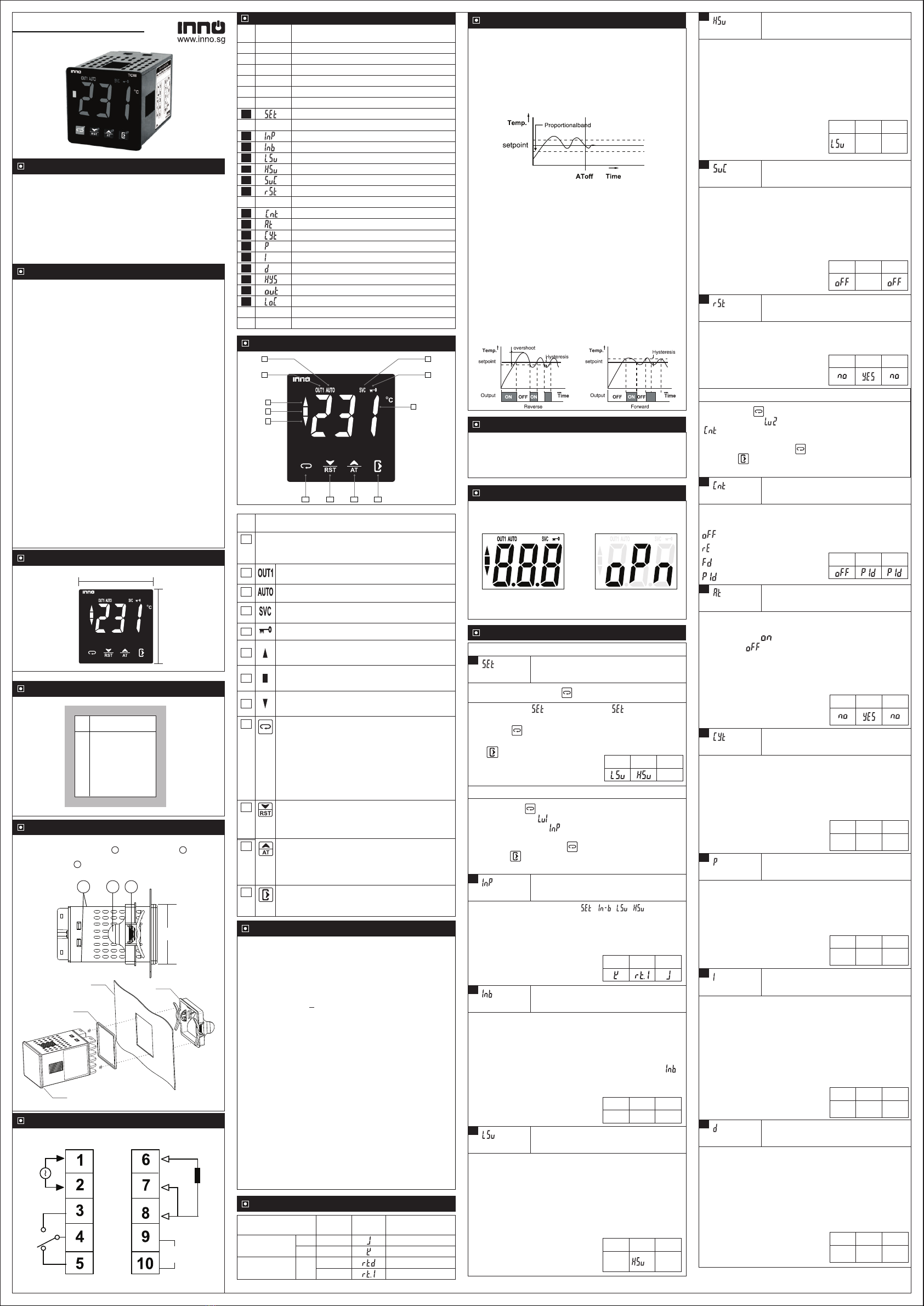
Installation : Fixing and dimensions of panel models:
To fix the unit, slide the fastener 1 through the guides 2 as per the
position shown in the figure. Move the fastener in the direction of the
arrow, pressing tab 3 it permits to move the fastener in the opposite
direction of the arrow.
45.5mm
45.5mm
Panel Cutout
Dimensions
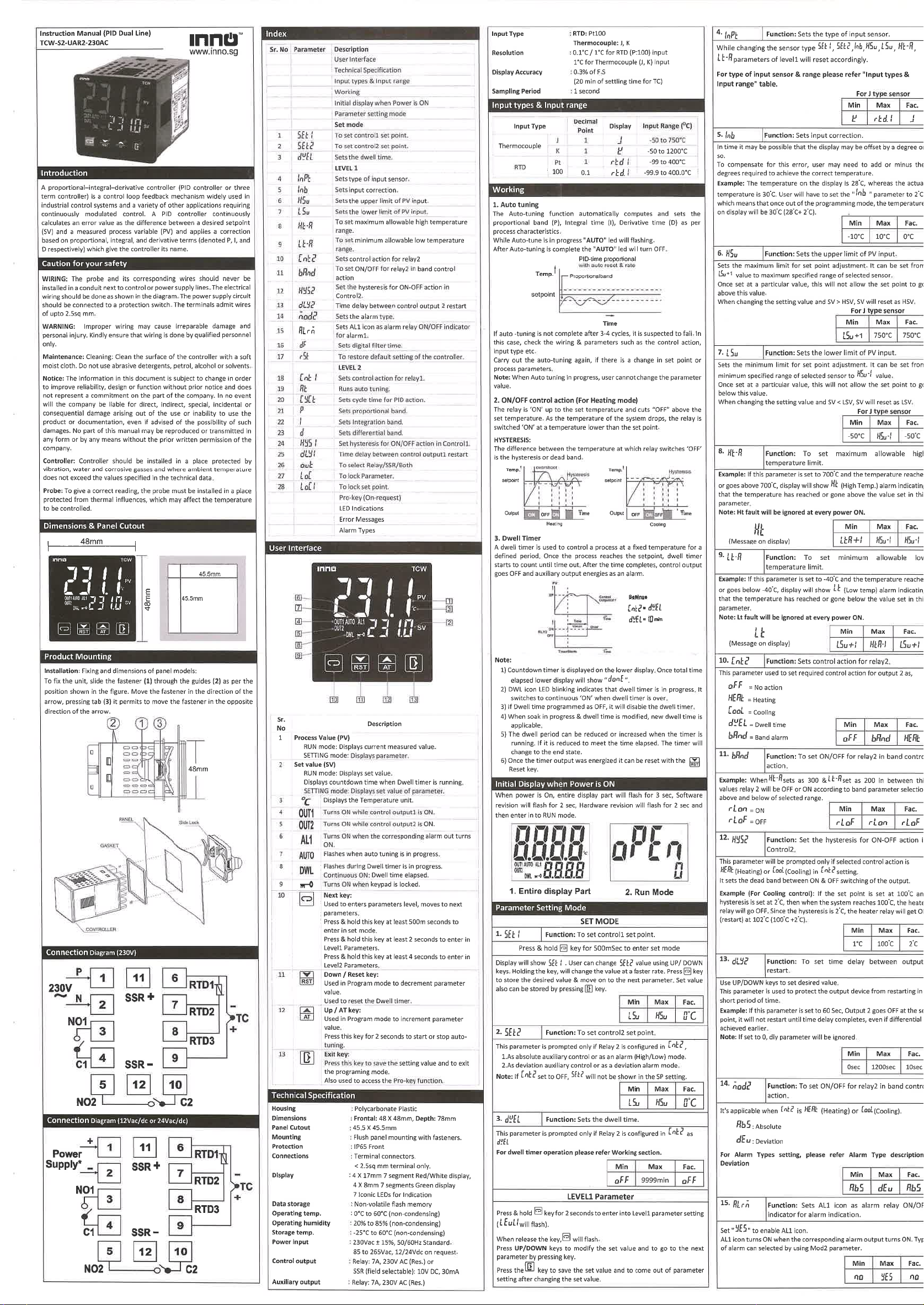
Connection Diagram
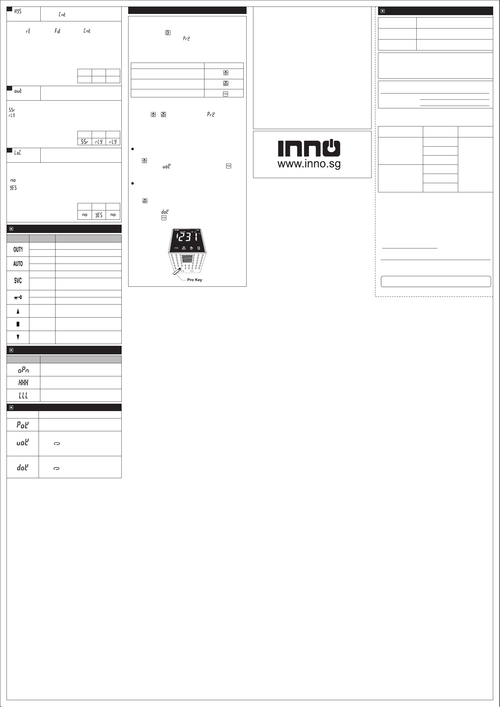
When power is supplied, whole display part will be flash for
6 sec and then enters in to RUN mode.
1. Whole display Part 2. Second Screen
Initial Display when Power is ON
Technical Specification
Display : 3 X 20mm 7 segment White display,
O
1 C for Thermocouple (J, K) input
85 to 265 VAC/DC on request.
Mounting : Flush panel mounting with fasteners
Protection : IP65 Front
< 2.5sq mm terminal only.
Data storage : Non-volatile flash memory
Storage temp : -25°C to 60°C (non-condensing)
Power input : 230 Vac ±15 % , 50-60Hz Standard.
Control output : Relay : 10A, 230V AC or
Connections : Terminal connectors.
SSR (field selectable) : 10V DC, 30mA
Thermocouple : J, K
Input Type : RTD : Pt100
O O
Resolution : 0.1 C / 1 C for RTD (Pt100) input
Dimensions : Frontal : 48 X 48mm, Depth : 78mm
O
Display Accuracy: RTD : 0.1% of F.S +/- 1 C
Housing : Polycarbonate Plastic
Panel Cutout : 45.5 X 45.5mm
7 Iconic LEDs for Indication
Operating temp. : 0°C to 60°C (non-condensing)
Operating humidity : 20% to 85% (non-condensing)
Thermocouple : 0.3% of F.S
Sampling Period : 1 second
(20 min of settling time for TC)
Parameter Setting Mode
Function: Sets the upper limit of PV input.
5
Parameter
Function: Sets the lower limit of PV input.
4
Parameter
For J type sensor
For J type sensor
Display will show . User can change value using UP/
DOWN keys. Holding the key, will change the value at a faster
rate. Press key to store the desired value & move on to
the next parameter. Set value also can be stored by pressing
Key
Function: To set control set point.
1
Parameter
Press & hold key for 1 seconds.
SP Setting
6
Parameter
Function : To set service time.
Example: If user set Service time to 10 days, then after 10
days of continuous service of machine, the SVC icon on
controller will lit to indicate that service time has been elapsed
or its time to service the machine
Service Time notify the machine user to carry out the machine
maintenance setted at predefined time or to indicate that, the
machine has worked for certain days.
Min Max
Fac.
999
Day
Function: Sets input correction.
3
Parameter
Min Max
Fac.
In time it may be possible that the display may be offset by a
degree or so.
To compensate for this error, user may need to add or minus the
degrees required to achieve the correct temperature.
O
Example : The temperature on the display is 28 C, whereas the
O
actual temperature is 30 C. User will have to set the " "
O
parameter to 2 C, which means that once out of the
O
programming mode, the temperature on display will be 30 C
O O
(28 C+ 2 C).
O
-20 C O
20 C O
0 C
LEVEL1 Parameter
Function: Sets the type of input sensor .
2
Parameter
Min Max
Fac.
For J type sensor
For type of input sensor & range please refer "Input types &
Input range" table.
8
9
10
11
12
Sets cycle time for PID action.
Sets proportional band.
Sets integration time.
Sets differential time.
Sets the hysterisis.
Runs auto tuning.
Set control action for relay / SSR.
Index
Sr.
No. Para. Description
1
3
4
5
6
7
Control set point.
Sets the type of input sensor .
Sets input correction.
Sets the lower limit of PV input.
Sets the upper limit of PV input.
13
14
15
16
Factory reset parameter.
Level1 Parameter
Sets Control output.
Lock keypad.
2
LED Indications
User Interface
Technical Specification
Initial display when Power is ON
Parameter setting mode
Working
Level2 Parameter
Error Messages
Input types & Input range
Set service time.
Min Max
Fac.
O
0 C
7
Parameter
Function : To restore default settings of
the controller.
When Set to Yes all parameter are programmed to factory
values.
Useful to debug setting related problems.
Min Max
Fac.
Min Max
Fac.
O
-50 C
Once set at a particular value, this will not allow the set point
to go above this value.
When changing the setting value and SV > HSV, SV is reset
as HSV.
Sets the maximum limit for set point adjustment. It can be
set from LSV+1 value to maximum specified range of
selected sensor.
While changing the sensor type , , ,
parameters of level1 will reset accordingly.
Once set at a particular value, this will not allow the set point
to go below this value.
When changing the setting value and SV < LSV, SV is reset
as LSV.
Sets the minimum limit for set point adjustment. It can be set
from minimum specified range of selected sensor to HSV-1
value.
Function: Sets cycle time for PID action.
10
Parameter
LEVEL2 Parameter
Function: Runs auto tunning.
9
Parameter
This parameter will be prompted only if selected control
action is PID in control parameters.
This parameter used to set YES/NO to start and stop Auto-
tuning.
When Setting as , the unit starts auto-tuning. After
Completing is automatically Set.
During auto-tuning, the AUTO indicator continuously ON.
Function: Sets control action for
relay/SSR.
8
Parameter
This parameter used to set required control action for
relay/SSR.
Min Max
Fac.
= PID
= No action
= Reverse
= Forward Min Max
Fac.
Cycle time also known as duty cycle, the total length of time for
the controller to complete one ON/OFF cycle.
Example : With a 20 second cycle time, an on time of 10
seconds and an OFF time of 10 seconds represents a 50
percent power output. The controller will cycle ON and OFF
while within the proportional band.
Min Max
Fac.
1 sec 60 sec 3 sec
Function: Sets differential time.
13
Parameter
Sets the differential time of PID parameter.
Min Max
Fac.
0
sec
999
sec
30
sec
Setting "0" will turn OFF differential.
Term D is a best estimate of the future trend of the SV-PV error,
based on its current rate of change. It is sometimes called
"anticipatory control", as it is effectively seeking to reduce the
effect of the SV-PV error by exerting a control influence
generated by the rate of error change. The more rapid the
change, the greater the controlling or dampening effect.
Function: Sets proportional band.
11
Parameter
Sets the proportional band of PID parameter.
Min Max
Fac.
O
0.1 C O
99.9 C O
10.0 C
Function: Sets integration time.
12
Parameter
Sets the integration time of PID parameter.
Min Max
Fac.
0
sec
999
sec
120
sec
Example : If the (SV-PV) error is large and positive, the
control output will be proportionately large and positive and
vice versa if error is negative.
Term P is proportional to the current value of the SV-PV
error .
Term I accounts for past values of the SV-PV error and
integrates them over time to produce the I term.
Example : If there is a residual SV-PV error after the
application of proportional control, the integral term seeks to
eliminate the residual error by adding a control effect due to the
historic cumulative value of the error.
Setting "0" will turn OFF integration.
A proportional–integral–derivative controller (PID controller or three
term controller) is a control loop feedback mechanism widely used in
industrial control systems and a variety of other applications requiring
continuously modulated control. A PID controller continuously
calculates an error value as the difference between a desired
setpoint (SV) and a measured process variable (PV) and applies a
correction based on proportional, integral, and derivative terms
(denoted P, I, and D respectively) which give the controller its name.
-1 O
-50 C
Min Max
Fac.
O
750 C
O
750 C
+1
User can Upload parameters settings from one controller
and download them to multiple controllers.
This will make on site parameter setting easy.
Pro-key (On Request)
The Auto-tuning function automatically computes and sets the
proportional band (P), Integral time (I), Derivative time (D) as
per process characteristics.
After Auto-tuning is complete the "AUTO" led will turn OFF.
While Auto-tune is in progress "AUTO" led will turn ON.
Carry out the auto-tuning again, if there is a change in setpoint
or process parameters.
If auto -tuning is not complete after 3-4 cycles, it is suspected to
fail. In this case, check the wiring & parameters such as the
control action, input type etc.
PID-time proportional
with auto reset & rate
Working
2. ON/OFF control action (For reverse mode)
The relay is ‘ON’ up to the set temperature and cuts”OFF”
above the set temperature . As the temperature of the system
drops ,the relay is switched ‘ON’ at a temperature slightly
lower than the set point .
The difference between the temperature at which relay
switches ‘OFF’ is the hysteresis or dead band.
HYSTERESIS:
1. Auto tuning
Note : In Auto Tunning running time, user can not change
the parameter value.
48mm
1
23
CONTROLLER
GASKET
PANEL Side Lock
Press & hold key for 4 seconds to enter into Level1
parameter setting( will flash).
Press the key to save the set value and to come out of
parameter setting after changing the set value.
When release the key, will flash.
Press UP/DOWN keys to modify the set value and to go to the
next parameter by pressing key.
Press UP/DOWN keys to modify the set value and to go to the
next parameter by pressing key.
will flash.
Press & hold key for 8 seconds to enter into Level2
parameter setting( will flash). When release the key,
Press the key to save the set value and to come out of
parameter setting after changing the set value.
TCW-S1-UR2-230AC TM
48mm
48mm
TCW
User Interface
TCW
2
1
3
5
4
6
7
8
119 10 12
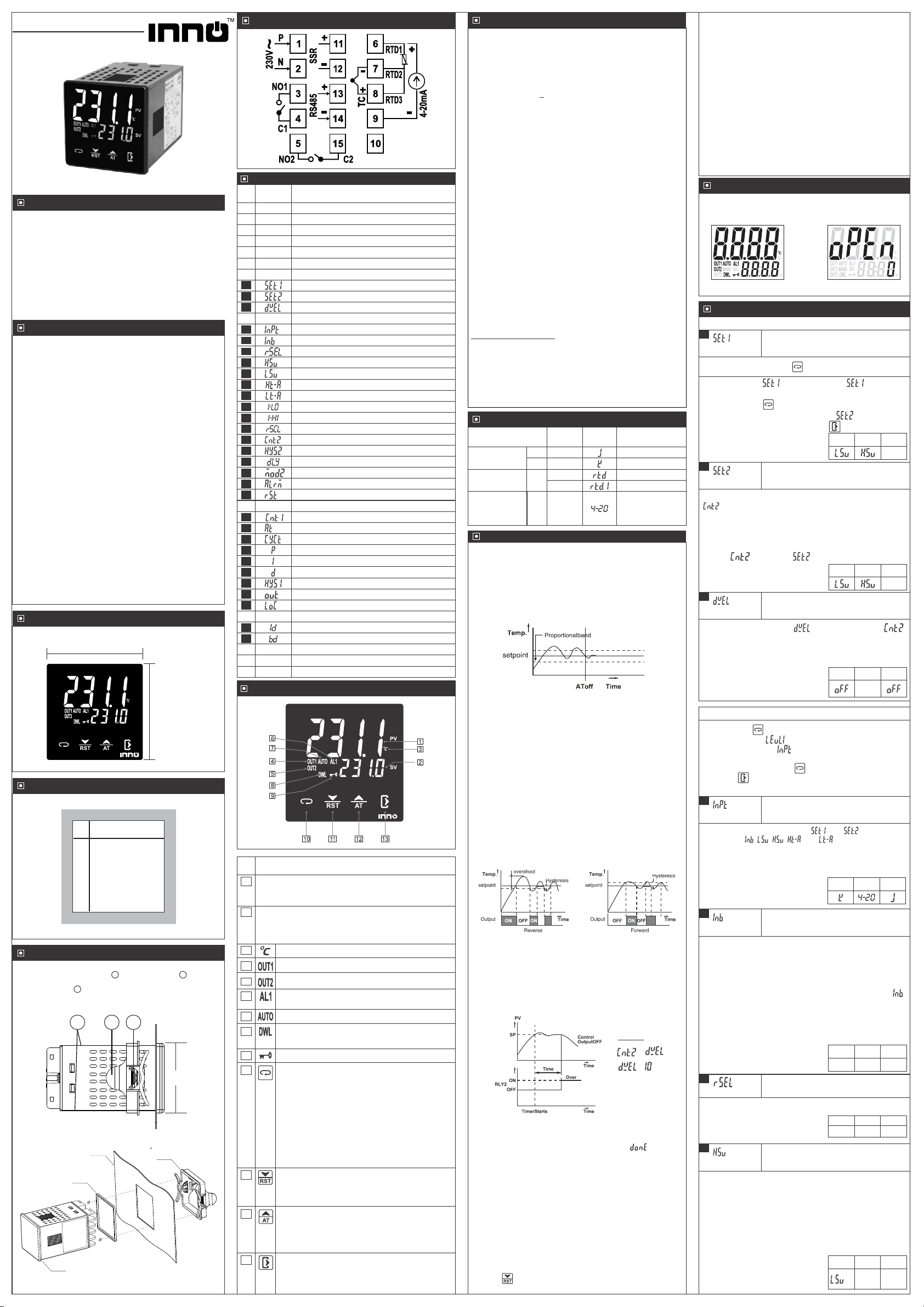
L
N
RTD
TC
+
-
NO
C
NC
SSR
+
-
Calibration Certificate
DATE
MODEL NO.
(20 min of settling time for TC inputs)
For TC inputs : 0.3% of FS
Claimed Accuracy :
O
For RTD inputs : 0.1% of FS +/-1 C
Valid Upto :
Calibration Instrument & Sr. No :
Calibrated ON :
The calibration of this unit has been verified at the following
values :
SENSOR TYPE
RTD
VALUE
O
TESTED ( C)
O
0 C
O
100 C
O
350 C
J,K
O
50 C
O
400 C
O
650 C
Instrument is confirmed accepted as accuracy is within the
specified limit. This certificate is valid upto one year from the
date of issue.
CONTROLLER
SR. NO.
Checked By :
INNO AUTOMATION INDIA PVT. LTD.
(Specification are subject to change, since development is a
continuos process.)
VALUE
O
Observed ( C)
All values
within
specified
limit of
accuracy
LED Indication
LED DescriptionStatus
ON
OFF Relay / SSR OFF.
Relay / SSR ON.
ON
OFF
Tunning is in progress.
Tunning Stop.
ON
OFF
Parameters are locked.
Parameters are unlocked.
ON
OFF Service time is in progress or
disabled.
Service time elapsed.
ON
O
The process value is > 5 C
than set point.
ON The process value is within the
O
5 C range of the set point.
ON
O
The process value is < 5 C
than set point.
This parameter is used to configure control out as,
User has to set this parameter in accordance with the output
used.
= Relay
= SSR
Error Messages
Message Description
When input sensor is disconnected or
sensor is not connected.
Flashes when measured value is higher
than input range.
Flashes when measured value is lower
than input range.
Function: Sets Control output.
15
Parameter
16
Parameter
Function: To lock keypad.
= Locked parameter
When locked all parameters can only be viewed ,but can not
be modified.
This parameter is used to lock the parameter so that
tampering is not possible by by-standers.
= unlocked parameter
Min Max
Fac.
Min Max
Fac.
Min Max
Fac.
O
1 C O
100 C O
2 C
It sets the deadband between ON & OFF switching of the
output.
This parameter will be prompted only if selected control
action is (reverse) or (forward) in setting.
O
Example (For Fd control) : If the set point is set at 100 C and
O O
hystresis is set at 2 C, then when the system reaches 100 C,
O
the heater relay will go OFF. Since the hystresis is 2 C, the
O O O
heater relay will get ON (restart) at 102 C (100 C +2 C).
Function: Sets the hystresis for ON-OFF
action in .
14
Parameter
Shows controller in Pro- key mode.
Parameter values are uploaded from
controller to pro key.
Press " " key to confirm uploading of
parameter values from controller to the Pro
key.
Message Description
Parameter values are downloaded from pro
key to controller.
Press " " key to confirm downloading of
parameter values from Pro key to controller.
Operating Messages (Pro-key Mode)
If user tries to enter Pro-key mode without inserting the pro key or
with wrong connection, no further function will be activated after
displaying “ or ”. Controller will display “ ”. Then switch off
controller and insert the pro key properly and try to enter Pro key
mode.
User has to first Upload the parameters in the Subzero Validated
Blank Pro-Key and then subsequently use it for downloading.
Uploading mode
Press key to upload the parameters to Pro Key.
Display will show " " once uploading is done. Press to exit
display will show "---" and return to normal display.
Downloading mode
Similarly connect Pro key to the controller .
Press key to download all parameters from Pro key to the
controller.
Display will show " " once download is done.
Once done press key to exit and display will flash and return to
normal mode.
To use Pro-key user must insert it prior to power ON. Insert the pro-
key and power ON controller. When the display flashes for 5
seconds, touch the key for 1 second. Controller will enter into
Pro-key mode and will display “ ”. Then touch either of the below
given keys to use the Pro-key.
Functions of Pro-key and the keys to be used for are as given below:
Function Keys to be Used
To upload the parameters from the
controller
To download the parameters to the
controller
To set and exit
touch " " key
touch " " key
touch " " key
Pro-Key ( On Request ) Disclaimer: This manual & its contents remain the sole property of
INNO AUTOMATION, India and shall not be reproduced or
distributed without authorization. Although great care has been taken
in the preparation of this document, the company or its vendors in no
event will be liable for direct, indirect, special, incidental or
consequential damage arising out of the use or inability to use the
product or documentation, even if advised of the possibility of such
damages. No part of this manual may be reproduced or transmitted
in any form or by any means without the prior written permission of
the company. INNO AUTOMATION, reserves the right to make and
changes or improvements without prior notice.
Warranty: This product is warranted against defects in materials and
workmanship for a period of one year from the date of purchase.
During the warranty period, product determined by us to be defective
in form or function will be repaired or, at our option, replaced at no
charge. This warranty does not apply if the product has been
damaged by accident, abuse, and misuse or as a result of service or
modification other than by the company. This warranty is in lieu of any
other warranty expressed or implied. In no event shall the company
be held liable for incidental or consequential damages, including lost
revenue or lost business opportunity arising from the purchase of this
product.
00 / 18.07.19_D&D
TM
Technical Specification
7 Iconic LEDs for Indication
Control output : (For TCW-S2-UAMR2-230AC)
Thermocouple : 0.3% of F.S
Sampling Period : 1 second
Relay : 5A, 230V AC (Res.) or
Data storage : Non-volatile flash memory
Storage temp : -25°C to 60°C (non-condensing)
O
Display Accuracy: RTD : 0.1% of F.S +/- 1 C
(20 min of settling time for TC)
Serial Communication:
Interface Standard : RS485
Transmission Mode : Half Duplex
Parity : None/Odd/Even
SSR (field selectable) : 10V DC, 30mA
Thermocouple : J, K
Analog: 4-20 mA.
Communication Address : 1 to 255, max of 32 units per line.
Transmission Protocol : Modbus RTU
Stop Bit : 1 or 2
Transmission Speed : 2400/4800/9600/19200/38400
Operating temp. : 0°C to 60°C (non-condensing)
Input Type : RTD : Pt100
O
1 C for Thermocouple (J, K) input
85 to 265Vac
Analog : 0.3% of F.S
Operating humidity : 20% to 85% (non-condensing)
O O
Resolution : 0.1 C / 1 C for RTD (Pt100) input
Power input : 230 Vac ±15 % , 50/60Hz Standard.
4 X 8mm 7 segment Green display
Auxiliary output : Relay : 5A, 230V AC (Res.)
O O O O
1 C/0.1 C/0.01 C/ 0.001 C for Analog Input
Mounting : Flush panel mounting with fasteners.
Protection : IP65 Front
Connections : Terminal connectors.
< 2.5sq mm terminal only.
Display : 4 X 17mm 7 segment Red/White display,
Housing : Polycarbonate Plastic
Dimensions : Frontal : 48 X 48mm, Depth : 78mm
Panel Cutout : 45.5 X 45.5mm
Input types & Input range
Input Type
Thermocouple J
K
1
Decimal
Point
1
Display Input Range
O
-50 to 750 C
O
-50 to 1200 C
RTD
Analog Input
Pt
100
1
0.1
1/0.1/0.01/
0.001
O
-99 to 400 C
O
-99.9 to 400.0 C
-1999 to 9999
(as per rSEL
decimal point
selected)
4-20
Note:
4) When soak in progress & dwell time is modified, new dwell
time is applicable .
6) Once the timer output was energized it can be reset with
2) DWL icon LED blinking indicates that dwell timer is in
progress. It switches to continuous ‘ON’ when dwell
timer is over.
3) If Dwell time programmed as OFF, it will disable the dwell
timer.
1) Countdown timer is displayed on the lower display. Once
total time elapsed lower display will show " ".
5) The dwell period can be reduced or increased when the
timer is running. if it is reduced to meet the time elapsed.
the timer will change to the end state.
the Reset key.
A dwell timer is used to control a process at a fixed temperature
for a defined period. Once the process reaches the setpoint,
dwell timer starts to count until time out . After the time
completes, control output goes OFF and auxiliary output
energises as an alarm.
3. Dwell Timer:
Settings
=
= min
10min
AfterAuto-tuning is complete the "AUTO" led will turn OFF.
WhileAuto-tune is in progress "AUTO" led will turn ON.
The Auto-tuning function automatically computes and sets the
proportional band (P), Integral time (I), Derivative time (D) as
per process characteristics.
Carry out the auto-tuning again, if there is a change in setpoint
or process parameters.
If auto -tuning is not complete after 3-4 cycles, it is suspected to
fail. In this case, check the wiring & parameters such as the
control action, input type etc.
PID-time proportional
with auto reset & rate
Working
2. ON/OFF control action (For reverse mode)
The relay is ‘ON’ up to the set temperature and cuts”OFF”
above the set temperature . As the temperature of the system
drops ,the relay is switched ‘ON’ at a temperature lower than
the set point .
HYSTERESIS:
The difference between the temperature at which relay
switches ‘OFF’ is the hysteresis or dead band.
1. Auto tuning
Note : In Auto Tuning running time, user can not change
the parameter value.
SETTING mode : Displays set value of parameter.
RUN mode : Displays set value.
Set value (SV)
Displays countdown time when Dwell timer is running.
4. RS 485 COMMUNICATION:
3 sec, software version will flash for 3 sec and then enter in to
RUN mode.
When power is On, entire display part will flash for
Initial Display when Power is ON
1. Entire display Part 2. Run Mode
Parameter Setting Mode
Function: To set control1 set point.
1
Parameter
SET MODE
Note: If set to OFF, will not be shown in the SET
MODE.
This parameter is prompted only if Relay 2 is configured in
2. As deviation auxiliary control or as a deviation alarm mode.
,
1. As absolute auxiliary control or as an alarm (High/Low)
mode.
Function: To set control2 set point.
2
Parameter
Min Max
Fac.
O
0 C
Press & hold key for 2 second.
Display will show . User can change value using
UP/ DOWN keys. Holding the key, will change the value at a
faster rate. Press key to store the desired value & move
on to the next parameter.( For 2 relays / Dwell). Set
value also can be stored by pressing Key
Min Max
Fac.
O
0 C
Function: Sets the dwell time.
3
Parameter
Min Max
Fac.
9999
min
For dwell timer operation please refer Working section.
It is used to control process at a fixed temp. for defined period.
This parameter prompted if function is selected in .
Function: Sets input correction.
5
Parameter
Min Max
Fac.
In time it may be possible that the display may be offset by a
degree or so.
To compensate for this error, user may need to add or minus
the degrees required to achieve the correct temperature.
O
Example : The temperature on the display is 28 C, whereas
O
the actual temperature is 30 C. User will have to set the " "
O
parameter to 2 C, which means that once out of the
O
programming mode, the temperature on display will be 30 C
O O
(28 C+ 2 C).
Note: For 4-20 Input, as per rSEL decimal point will be
selected.
O
-20 C
O
20 C
O
0 C
LEVEL1 Parameter
Press the key to save the set value and to come out of
parameter setting after changing the set value.
Press & hold key for 4 seconds to enter into Level1
parameter setting( will flash).
When release the key, will flash.
Press UP/DOWN keys to modify the set value and to go to the
next parameter by pressing key.
Function: Sets the type of input sensor .
4
Parameter
For type of input sensor & range please refer "Input types
& Input range" table.
While changing the sensor type and , parameter
of level 1 ie, , , , and will reset
accordingly.
Function: To set resolution for Analog
Input.
6
Parameter
Min Max
Fac.
This parameter is prompted when input is selected as 4-20.
1 1
0.001
Function: Sets the upper limit of PV input.
7
Parameter
Once set at a particular value, this will not allow the set
point to go above this value.
When changing the setting value and SV > HSV, SV is reset
as HSV.
Min Max
Fac.
O
750 C
For J type sensor
Sets the maximum limit for set point adjustment. It can be
set from LSV+1 value to maximum specified range of
selected sensor.
O
750 C
+1
Min Max
Fac.
ŸUser can read/write any parameter value in memory
resistor map.
ŸIf communication is not working then check related
hardware.
ŸIf baud rate and slave Id does not match communication
will not take place.
Note:
2. Open the Communication software like ModbusMat
/Modpoll or any custom software.
5. Once communication is established all present values of
TCW-S2 will be displayed.
1. Connect the TCW-S2 to PC/Laptop with the help of
suitable Converter (RS-485 to USB).
3. Do following configuration - COM Port , Baud rate, Device Id
at both side.
4. Select Register Address of required parameters as per
register map and start communication.
Caution for your safety
Maintenance: Cleaning: Clean the surface of the controller with a
soft moist cloth. Do not use abrasive detergents, petrol, alcohol or
solvents.
Probe :To give a correct reading, the probe must be installed
in a place protected from thermal influences, which may
affect the temperature to be controlled.
Notice: The information in this document is subject to change in
order to improve reliability , design or function without prior notice
and does not represent a commitment on the part of the company.
In no event will the company be liable for direct, indirect, special,
incidental or consequential damage arising out of the use or
inability to use the product or documentation, even if advised of
the possibility of such damages. No part of this manual may be
reproduced or transmitted in any form or by any means without
the prior written permission of the company.
Controller :Controller should be installed in a place
protected by vibration, water and corrosive gasses and
where ambient temperature does not exceed the values
specified in the technical data.
WIRING: The probe and its corresponding wires should never be
installed in a conduit next to control or power supply lines. The
electrical wiring should be done as shown in the diagram. The
power supply circuit should be connected to a protection switch.
The terminals admit wires of upto 2.5sq mm.
WARNING: Improper wiring may cause irreparable damage and
personal injury. Kindly ensure that wiring is done by qualified
personnel only.
Product Mounting
Installation : Fixing and dimensions of panel models:
To fix the unit, slide the fastener 1 through the guides 2 as per the
position shown in the figure. Move the fastener in the direction of the
arrow, pressing tab 3 it permits to move the fastener in the opposite
direction of the arrow.
45.5mm
45.5mm
Panel Cutout
Dimensions
48mm
48mm
PV
SV
TCW-S2
Operating Manual
TCW-S2-UAMR2
Introduction
A proportional–integral–derivative controller (PID controller or three
term controller) is a control loop feedback mechanism widely used in
industrial control systems and a variety of other applications requiring
continuously modulated control. A PID controller continuously
calculates an error value as the difference between a desired
setpoint (SV) and a measured process variable (PV) and applies a
correction based on proportional, integral, and derivative terms
(denoted P, I, and D respectively) which give the controller its name.
PT244-TX is a two set point PID controller. It is available in touch with
RS-485 communication. Customized iconic display interprets status
easily.
CONTROLLER
GASKET
PANEL Side Lock
48mm
1
23
User Interface
Connection Diagram ( for TCW-S2-UAMR2)
Sr.
No. Description
RUN mode : Displays current measured value.
SETTING mode : Displays parameter.
Process Value (PV)
Turns ON while control output1 is ON.
4
2
1
Displays the Temperature unit.
3
8
Turns ON while control output2 is ON.
Turns ON when auto tuning is in progress.
5
7
Flashes during Dwell timer is in progress.
Continuous ON : Dwell time elapsed.
ON.
Turns ON when the corresponding alarm out turns
6
9Turns ON when keypad is locked.
10
Used to enters parameters level, moves to next
Next key :
parameters.
in Level1 Parameters.
in Level2 Parameters.
Press & hold this key atleast 8 seconds to enter
in Level3 Parameters.
Press & hold this key atleast 2 seconds to enter
in set mode.
Press & hold this key atleast 4 seconds to enter
Press & hold this key atleast 6 seconds to enter
11
Used to reset the Dwell timer..
value.
Down / Reset Key :
Used in Program mode to decrement parameter
13
Press this key for 2 seconds to start or stop auto-
tuning.
value.
Up /AT Key :
Used in Program mode to increment parameter
12
the programing mode.
Press this key to save the setting value and to exit
Exit Key :
1
3
4
5
6
7
9
10
14
11
Control1 set point.
Sets the type of input sensor .
Sets input correction.
Sets the upper limit of PV input.
To set resolution for Analog Input.
Sets control action for relay2.
Input value scaling point 1.
Sets the hysteresis2.
Sets the dwell time.
15
Level1 Parameter
2Control2 set point.
8Sets the lower limit of PV input.
Sets the alarm type.
Sets AL1 icon as alarm relay.
17
18
19 Factory reset parameter.
Index
Sr.
No. Para. Description
User Interface
Technical Specification
Initial display when Power is ON
Parameter setting mode
Working
Input types & Input range
Set mode
Low temperature limit.
High temperature limit.
LED Indications
Alarm Types
Error Messages
Sets cycle time for PID action.
Sets proportional band.
Sets integration time.
Sets differential time.
Sets the hysteresis1
Runs auto tuning.
Set control action for relay1 / SSR.
20
21
22
23
24
Sets Control1 output.
25
Lock keypad.
26
Level2 Parameter
27
28
12 Input value scaling point 2.
13 To set reverse scaling for Analog input.
Sets time delay between output relay restart.
16
To set baud rate for communication.
To set device ID.
29
30
Level3 Parameter
TCW-S2

Function: Sets cycle time for PID action.
22
Parameter
Min Max
Fac.
1 sec 60 sec 3 sec
Cycle time also known as duty cycle, the total length of time for
the controller to complete one ON/OFF cycle.
Example : With a 20 second cycle time, an on time of 10
seconds and an OFF time of 10 seconds represents a 50
percent power output. The controller will cycle ON and OFF
while within the proportional band.
Function: Runs auto tunning.
21
Parameter
During auto-tuning, the AUTO icon is continuously ON.
This parameter will be prompted only if selected control
action is PID in .
This parameter is used to set YES/NO to start and stop Auto-
tuning.
When Setting as , the unit starts auto-tuning. After
Completing is automatically Set.
Min Max
Fac.
Sets the proportional band of PID parameter.
Min Max
Fac.
O
0.1 C O
100.0 C O
10.0 C
Example : If the (SV-PV) error is large and positive, the control
output will be proportionately large and positive and vice versa if
error is negative.
Term P is proportional to the current value of the SV-PV error .
Function: Sets proportional band.
23
Parameter
Parameter
Function: Sets integration time.
24
Sets the integration time of PID parameter.
Min Max
Fac.
0 sec 2000 sec 120 sec
Term I accounts for past values of the SV-PV error and
integrates them over time to produce the I term.
Setting "0" will turn OFF integration.
Example : If there is a residual SV-PV error after the
application of proportional control, the integral term seeks to
eliminate the residual error by adding a control effect due to
the historic cumulative value of the error.
Function: Set the hysteresis width for ON-
OFF action in Control1.
26
Parameter
Min Max
Fac.
O
1 C O
100 C O
2 C
This parameter will be prompted only if selected control action
is (reverse) or (forward) in setting.
It sets the deadband between ON & OFF switching of the
output.
O
Example (For Fd control) : If the set point is set at 100 C and
O O
hysteresis is set at 2 C, then when the system reaches 100 C,
O
the heater relay will go OFF. Since the hysteresis is 2 C, the
O O O
heater relay will get ON (restart) at 102 C (100 C +2 C).
Function: Sets differential time.
25
Parameter
Sets the differential time of PID parameter.
Setting "0" will turn OFF differential.
Term D is a best estimate of the future trend of the SV-PV error,
based on its current rate of change. It is sometimes called
"anticipatory control", as it is effectively seeking to reduce the
effect of the SV-PV error by exerting a control influence
generated by the rate of error change. The more rapid the
change, the greater the controlling or dampening effect.
Min Max
Fac.
0 sec 1000 sec 30 sec
Function: Sets control action for
relay1/SSR.
20
This parameter is used to set required control action for
relay 1/SSR as,
Parameter
28
Parameter
Function: To lock keypad.
= unlocked parameter
= Locked parameter
When locked all parameters can only be viewed ,but can not
be modified.
This parameter is used to lock the parameter so that
tampering is not possible by by-standers.
Min Max
Fac.
Function: Sets Control1 output.
27
Parameter
User has to set this parameter in accordance with the output
used.
This parameter is used to configure out as,
= SSR
= Relay
Min Max
Fac.
= Reverse
= Forward
= PID Min Max
Fac.
LEVEL2 Parameter
Press the key to save the set value and to come out of
parameter setting after changing the set value.
will flash.
Press & hold key for 6 seconds to enter into Level2
parameter setting( will flash). When release the key,
Press UP/DOWN keys to modify the set value and to go to the
next parameter by pressing key.
LED Indication
LED Description
Status
ON
OFF Relay1 / SSR OFF.
Relay1 / SSR ON.
ON
OFF Relay2 OFF.
Delay timer is running.
Relay2 ON.
ON
OFF
Tuning is in progress.
Tuning Stop.
FLASHING
FLASHING
ON Dwell time elapsed.
Dwell timer is in progress.
Alarm relay ON.
Alarm Relay OFF.
ON
OFF
ON
OFF
Parameters are Locked.
Parameters are Unlocked.
OFF Dwell timer disabled.
ON Alarm indication ON.
OFF Alarm indication OFF.
Min Max
Fac.
2.4 9.638.4
Disclaimer: This manual & its contents remain the sole property of
INNO Automation . India and shall not be reproduced or distributed
without authorization. Although great care has been taken in the
preparation of this document, the company or its vendors in no event
will be liable for direct, indirect, special, incidental or consequential
damage arising out of the use or inability to use the product or
documentation, even if advised of the possibility of such damages.
No part of this manual may be reproduced or transmitted in any form
or by any means without the prior written permission of the company.
INNO Automation reserves the right to make and changes or
improvements without prior notice.
Warranty: This product is warranted against defects in materials and
workmanship for a period of one year from the date of purchase.
During the warranty period, product determined by us to be defective
in form or function will be repaired or, at our option, replaced at no
charge. This warranty does not apply if the product has been
damaged by accident, abuse, and misuse or as a result of service or
modification other than by the company. This warranty is in lieu of any
other warranty expressed or implied. In no event shall the company
be held liable for incidental or consequential damages, including lost
revenue or lost business opportunity arising from the purchase of this
product.
Calibration Certificate
DATE
MODEL NO.
(20 min of settling time for TC inputs)
Claimed Accuracy :
For TC inputs : 0.3% of FS
For Analog inputs : 0.3% of FS
O
For RTD inputs : 0.1% of FS +/-1 C
Calibration Instrument & Sr. No :
Calibrated ON :
Valid Upto :
The calibration of this unit has been verified at the following
values :
Instrument is confirmed accepted as accuracy is within the
specified limit. This certificate is valid upto one year from the
date of issue.
CONTROLLER
SR. NO.
Checked By :
INNO Automation, Chennai-600032
(Specification are subject to change, since development is a
continuos process.)
SENSOR TYPE
RTD
VALUE
O
TESTED ( C)
O
0 C
O
100 C
O
350 C
J,K
Analog
O
50 C
4 mA
O
400 C
12 mA
O
650 C
20 mA
VALUE
O
Observed ( C)
All values
within
specified
limit of
accuracy
Error Messages
Message Description
Displays when input sensor is disconnected
or sensor is not connected.
Flashes when measured value is higher
than input range.
Flashes when measured value is lower
than input range.
temperature limit.
Temperature above the maximum high
temperature limit.
Temperature below the minimum low
=
=
=
=
=
=
=
=
=
Alarm Types
Setting Alarm Type Description
Deviation high limit alarm
Deviation low limit alarm
Absolute value high limit
alarm
Absolute value low limit
alarm
* : Alarm output hysteresis
High temperature alarm
Low temperature alarm
Alarm OFF when PV = SV
SV = +
FDAlarm ON when PV < SV -
Alarm OFF when PV = SV
SV = +
FDAlarm ON when PV > SV +
Alarm ON when PV < SV -
SV =
Alarm OFF when PV = SV
Alarm OFF when PV = SV
SV =
Alarm ON when PV > SV +
PV >
PV <
=
=
=
(Message on display)
Useful to debug setting related problems.
19
Parameter
Function : To restore default settings of
the controller.
When Set to all parameter are programmed to factory
values.
Min Max
Fac.
Function: Set the hysteresis for ON-OFF
action for Relay2.
15
Min Max
Fac.
O
1 C
Parameter
O
100 C O
2 C
It sets the deadband between ON & OFF switching of the
output.
This parameter will be prompted only if selected control action
is rE (reverse) or Fd (forward) in setting.
O
Example (For Fd control) : If the set point is set at 100 C and
O O
hysteresis is set at 2 C, then when the system reaches 100 C,
O
the heater relay will go OFF. Since the hysteresis is 2 C, the
O O O
heater relay will get ON (restart) at 102 C (100 C +2 C).
Note: For 4-20 Input, as per rSCL decimal point will be
selected.
Function: Sets the alarm type.
17
(forward).
It's applicable when action is (reverse) or
: Deviation
: Absolute
Parameter
For alarm types setting , please
refer Alarm Type description. Min Max
Fac.
18
Type of alarm can selected by using parameter.
Set " " to enable AL1 icon.
AL1 icon turns ON when the corresponding alarm output
turns ON.
Parameter
Function: Sets AL1 icon as alarm relay
ON/OFF indicator for alarm indication.
Min Max
Fac.
Function: Input value scaling point 1.
11
Parameter
To set the lower value of the analog input signal.
This parameter is prompted when input is selected as 4-20.
Parameter
Function: To set maximum allowable high
temperature limit.
9
O
Example: If this parameter is set to 700 C and the
O
temperature reaches or goes above 700 C, display will show
(High Temp.) alarm indicating that the temperature has
reached or gone above the value set in this parameter.
(Message on display)
Note : Ht fault will be ignored at every power ON.
Parameter
Function: To set minimum allowable low
temperature limit.
10
O
Example: If this parameter is set to -40 C and the temperature
O
reaches or goes below -40 C, display will show (Low temp)
alarm indicating that the temperature has reached or gone
below the value set in this parameter.
Note : Lt fault will be ignored at every power ON.
Function: Sets the lower limit of PV input.
8
Parameter
Min Max
Fac.
Once set at a particular value, this will not allow the set point
to go below this value.
O
-50 C
For J type sensor
When changing the setting value and SV < LSV, SV is reset
as LSV.
Sets the minimum limit for set point adjustment. It can be set
from minimum specified range of selected sensor to HSV-1
value.
O
-50 C
- 1
Min Max
Fac.
4 mA 4 mA
Function: Input value scaling point 2.
12
Parameter
This parameter is prompted when input is selected as 4-20.
To set theupper value of the analog input signal.
Min Max
Fac.
20 mA20 mA
Function: To set reverse scaling for
analog input.
13
Parameter
Min Max
Fac.
Function: Sets control action for relay2.
14
This parameter is used to set required control action for
relay 2 as,
Parameter
= Off
= Reverse
= Forward
= Dwell time
Reverse scaling for analog input is achieved when this
parameter is set to “ ”.
Example: For 4mA input display will show 9999 and for 20mA
input display will show -1999.
Function: To set time delay between
output relay restart.
16
Parameter
Min Max
Fac.
1200
Sec
0 Sec 0 Sec
Use UP/DOWN keys to set desired value.
Example: If this parameter is set to 60 Sec, Output 2 relay
goes OFF at the set point, it will not restart until time delay
completes, even if differential is achieved earlier.
This parameter is used to protect the output device from
restarting in a short period of time.
Note: If set to 0, dly parameter will be ignored.
Min Max
Fac.
Min Max
Fac.
LEVEL3 Parameter
Press & hold key for 8 seconds to enter into
parameter setting( will flash). When release the key,
will flash.
Press UP/DOWN keys to modify the set value and to go to the
next parameter by pressing key.
Press the key to save the set value and to come out of
parameter setting after changing the set value.
29
Parameter
Function: To set device Id.
To communicate properly controller
side and PC side Id should match.
Min Max
Fac.
11
255
30
Parameter
Function: To set baud rate for communication.
To communicate properly controller side and PC side baud rate
should match.
Range: 2400,4800,9600,19200,38400
Note: For 4-20 Input, as per rSCL decimal point will be
selected.
Min Max
Fac.
Table of contents
Other INNO Measuring Instrument manuals


Popular Measuring Instrument manuals by other brands


PCB Piezotronics
PCB Piezotronics IMI SENSORS M646B11 Installation and operating manual

NTI
NTI ENVIROMUX Series instruction manual

Storch
Storch ISO MARK manual

Lafayette Instrument
Lafayette Instrument J00111 user manual

QUINN
QUINN 57460 Owner's manual & safety instructions

AEI Security & Communications
AEI Security & Communications CTVM300AFR quick start guide