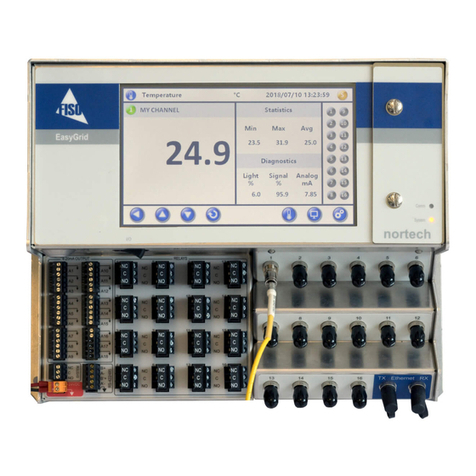
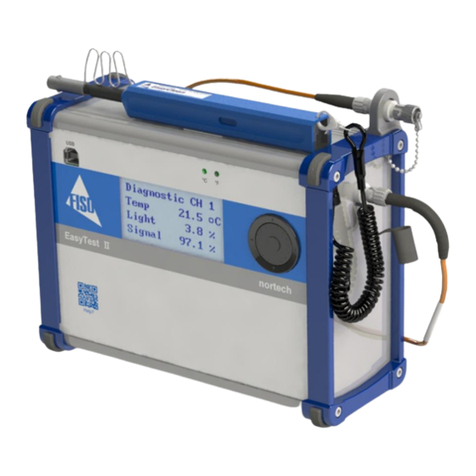
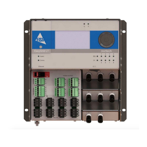
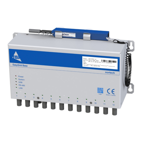
Fiso EasyGrid User manual

EasyGrid Base User Guide v1.0
EasyGrid Base
User Guide
MAN
-
00112

EasyGrid Base User Guide v1.0
All rights reserved. No part of this publication may be reproduced, stored in a retrieval system, or transmitted
in any form, be it electronically, mechanically, or by any other means such as photocopying, recording, or
otherwise, without the prior written permission of FISO.
Information provided by FISO is believed to be accurate and reliable. However, no responsibility is assumed by
FISO for its use nor for any infringements of patents or other rights of third parties that may result from its use.
No license is granted by implication or otherwise under any patent rights of FISO.
FISO s Commerce and Government Entities (CAGE) code under the North Atlantic Treaty Organization
(NATO) is L0294.
The information contained in this publication is subject to change without notice.
© 2018 FISO Technologies Inc.
Words that FISO considers trademarks have been identified as such. However, neither the presence nor absence
of such identification affects the legal status of any trademark.
Units of measurement in this document conform to SI standards and practices.
Fiso Technologies Inc.
00, Ave St-Jean-Baptiste, suite 19
Québec (Québec)
G E R9, Canada
Tel : +1 418 688 806
Fax : +1 418 688 8067
support@fiso.com
www.fiso.com

EasyGrid Base User Guide v1.0
3
1 Table of Content
2 Product Certification.................................................................................................................................... 4
2.1 CE Information ................................................................................................................................ 4
2.2 Independent Laboratory Testing..................................................................................................... 4
2.3 Declaration of conformity ...............................................................................................................
3 Safety nformation ....................................................................................................................................... 7
3.1 Conventions .................................................................................................................................... 7
3.2 Safety Information .......................................................................................................................... 8
3.3 Unpacking and Inspection ............................................................................................................... 9
4 Hardware Configuration ............................................................................................................................ 10
4.1 Introducing the EasyGrid Base ...................................................................................................... 10
4.2 Front Panel Overview .................................................................................................................... 10
4.3 Side Panel Overview ...................................................................................................................... 11
4.4 Grounding Terminal ...................................................................................................................... 11
4. Powering the EasyGrid Base ......................................................................................................... 12
4.6 Optical Connectors ........................................................................................................................ 12
4.7 Protective Dust Caps ..................................................................................................................... 13
4.8 LED Indicators Explained ............................................................................................................... 14
4.9 Analog Outputs ............................................................................................................................. 1
4.10 Connection - USB ........................................................................................................................ 1
4.11 Connection - Ethernet ................................................................................................................. 16
4.12 Connection – RS-48 / RS-422 .................................................................................................... 17
4.13 RS-48 / RS-422 Network Recommendations............................................................................. 18
4.14 Physical Dimensions .................................................................................................................... 19
5 Wiring nformation .................................................................................................................................... 20
.1 General .......................................................................................................................................... 20
.2 Power ............................................................................................................................................ 20
.3 Analog output ............................................................................................................................... 21
.4 Analog Output Scale ...................................................................................................................... 22
. System Relay ................................................................................................................................. 23
.6 RS-48 / RS-422 ............................................................................................................................. 24
6 Nortech Client Software ......................................................................................................................... 26
7 Troubleshooting ......................................................................................................................................... 27
7.1 Solving Common Problems ........................................................................................................... 27
7.2 Diagnostics .................................................................................................................................... 28
7.3 Sensor’s Light levels ...................................................................................................................... 28
7.4 Sensor’s Signal levels..................................................................................................................... 29
7. Power Protection Fuse .................................................................................................................. 29
8 Warranty and Service ................................................................................................................................ 30
8.1 General Information...................................................................................................................... 30
8.2 Liability .......................................................................................................................................... 30
8.3 Exclusions ...................................................................................................................................... 30
8.4 Certification ................................................................................................................................... 30
8. Transportation .............................................................................................................................. 31
8.6 FISO Service Center ....................................................................................................................... 31
8.7 Product disposal ............................................................................................................................ 31

EasyGrid Base User Guide v1.0
4
2 Product Certification
2.1 CE Information
Electronic test equipment is subject to the EMC Directive in the European
Union. The EN61326 standard prescribes both emission and immunity
requirements for laboratory, measurement, and control equipment.
This unit has been tested and found to comply with the limits for a Class B
digital device.
Please refer to the Declaration of Conformity.
2.2 Independent Laboratory Testing
This unit has undergone extensive testing according to the European Union Directive and Standards.
Tests were performed externally, at an independent, accredited laboratory. This guarantees the unerring
objectivity and authoritative compliance of all test results.
Use of shielded remote I/O cables, with properly grounded shields and metal connectors, is recommended in
order to reduce radio frequency interference that may emanate from these cables.
Shielded I/O cables are recommended to improve protection against lightning surge if unit or cables are
installed in outdoor area. See certificate and tests of compliance.
EasyGrid Base has been extensively tested to stringent environmental standards to ensure it remains reliable
when used under published specifications.

EasyGrid Base User Guide v1.0
2.3 Declaration of conformity
EU Declaration of Conformity
Manufacturer Name: FISO Technologies Inc.
A ress: 500, Saint-Jean-Baptiste Ave., Suite 195, Quebec, QC, Canada G2E 5R9
e hereby declare under our sole responsibility that the following apparatus:
Pro uct escription: Fiber optic thermometer
Mo el number(s): EasyGri Base
Pro uct category: Electrical equipment for measurement, control an laboratory use.
Complies with the essential requirements of the following applicable European Directive:
2014/30/EU Electromagnetic Compatibility (EMC) Directive,
2011/65/EU Restriction of the use of certain Hazardous Substances (RoHS) Directive
Conformity is assessed in accordance to the following standards:
EMC Stan ar s:
EN61326
-
1 : 2013
Emissions/Immunity requirements for laboratory Equipment
EN60255
-
26 : 2013
Measuring Relays and protection equipment: electromagnetic compatibility requirements
CISPR 11:2015 A1(2016)
EN 55011:2016 A1(2017) Measurement of conducted emission Group 1, class A (Industrial)
CISPR 11:2015 A1(2016)
EN 55011:2016 A1(2017) Measurement of radiated emission Group 1, class A (Industrial)
IEC 61000
-
4
-
2 : 2008
IEC 60255-22-2 : 2008
1
Electrostatic discharge immunity
±8kV Contact
Discharge
±15kV Air Discharge
IEC 61000
-
4
-
3 : 2006
A1(2007) A2(2010)
IEC 60255-22-3 : 2007
1
Radiated electromagnetic field immunity
10V/m, 80-3000MHz
Spot frequencies : 80MHz, 160MHz, 380MHz, 450MHz,
900MHz, 1850MHz, 2150MHz: 10V/m
IEC 61000
-
4
-
4 : 2012
IEC 60255-22-4 : 2008
1
Electrical fast transient immunity (EFT) ±4kV Power Lines, ±4kV I/O
IEEE C37.90.1: 2012
Fast Transient Surge ithstand Capability
±4kV Power Lines, ±4kV I/O
IEC 61000-4-5 : 2014
IEC 60255-22-5 : 2008
1
Surge immunity
Power:
±2kV L
-
PE / ±1kV L
-
L
I/O Ports: ±2kV L-PE / ±1kV L-L
Communication Ports: ±2kV L-PE
IEC 61000
-
4
-
6 : 2013
IEC 60255
-
22
-
6 : 2001
1
Conducted disturbance induced by RF fields 10Vrms
IEC 61000-4-8 : 2009 Power Frequency Magnetic Field immunity
100A/m
permanent
300A/m short duration
IEC 61000
-
4
-
9 : 2016
Pulse magnetic field immunity
1000A/m
IEC 61000-4-11 : 2004 Voltage dips, short interruptions and voltage
variation immunity
1 Cycle / 0%, 10 Cycles / 40%, 25 Cycles / 70%,
250 Cycles / 80%, 250 Cycles / 0%
IEC 60255
-
5 : 2000
2
IEC 60255-27 : 2013 Impulse voltage withstand test ±5kV
IEC 61000
-
4
-
18 : 2006
A1(2010)
IEC 60255-22-1 : 2007
1
IEEE C37.90.1 : 2012
Burst disturbance 2.5kV 2s
IEEE C37.90 : 2005
Dielectric Strength (RS
-
485 Circuit Only)
4.2kV
1
These standards have been replaced by IEC 60255-26:2013
2
This standard has been replaced by IEC 60255-27:2013

EasyGrid Base User Guide v1.0
6
Shock, vibration an transportation:
IEC 60255
-
21
-
1 : 1988
Vibration: response , endurance
Severity Class 2
IEC 60255
-
21
-
2 : 1988
-
10
Shock: response, withstand and bump test
Severity Class 2
IEC 60255
-
21
-
3 : 1993
-
09
Seismic test
Severity
Class 2
MIL
-
STD
-
810G
w/change1, (2014)
Transport vibrations
(Method 514.7)
Category 4
Environmental Affairs:
EN50581 : 2012
Articles manufactured on or after the Date of Issue of this declaration of Conformity do not
contain any of the restricted substances in concentration/applications not permitted by the
RoHS Directive
Supplementary information:
FCC Part 15 (2018) subpart B, Class A
This product meet the EMC requirement of the United States
ICES
-
003 (2016), Class A
This product meet the EMC
requirement of the Canada
IPC
-
CC
-
830
MIL
-
I
-
46058C
Environmental protection, conformal coating
Signed for and on behalf of FISO Technologies Inc.
Issued in : Quebec, Qc, Canada
Date:
November 15
th
2018
Frederic Borne, General Manager, FISO Technologies Inc.

EasyGrid Base User Guide v1.0
7
3 Safety Information
3.1 Con entions
Before using the product described in this guide, you should understand the following conventions:
DANGER
Indicates a potentially hazardous situation that, if not avoided, could result in death or
serious injury. Do not proceed unless you understand and meet the required conditions.
WARN NG
Indicates a potentially hazardous situation that, if not avoided, may result in minor or
moderate injury. Do not proceed unless you understand and meet the required conditions.
CAUT ON
Indicates a potentially hazardous situation that, if not avoided, may result in component
damage. Do not proceed unless you understand and meet the required conditions.
MPORTANT
Refers to information about this product you should not overlook.

EasyGrid Base User Guide v1.0
8
3.2 Safety Information
The level of radiation is below the level known to cause eye injury through accidental short-term exposure.
However, avoid prolonged exposure to light emitted from the fiber and do not stare directly at a light beam,
visible or not.
The following safety instructions must be observed whenever the EasyGrid Base is operated. Failure to
comply with any of these instructions or with any precaution or warning contained in the Fiber Optic
Thermometer and Client Software user’s guide is in direct violation of the standards of design, manufacture
and intended uses of the EasyGrid Base. FISO assumes no liability for the customer failure to comply with
these safety requirements.
THIS PRODUCT IS NOT DESIGNED FOR USE IN LIFE SUPPORT OR CRITICAL APPLICATIONS.
In no case will FISO be liable to the buyer, or to any third parties, for any consequential damage or indirect
damage which is caused by product failure, malfunction, or any other problem.
When using any electrical appliance, basic safety precautions should be followed, including the following:
FISO recommends using SEN-PS-EXT power supply with your monitor and verify that the voltage specifications
indicated on the power supply are compatible with the AC voltage and frequency delivered at the power
outlet.
Do not operate in wet/damp conditions.
Do not expose to outdoor conditions. Install the unit in a protective enclosure.
Do not operate in an explosive atmosphere.
Keep product surfaces clean and dry.
WARN NG
This equipment must be used as specified or the protection provided by the equipment may
be compromised. You must use this product in a normal mode and should not deviate from
the written instructions provided.

EasyGrid Base User Guide v1.0
9
3.3 Unpacking and Inspection
The EasyGrid Base monitor is shipped inside a carton designed to give maximum protection during shipment.
If the outside of the shipping carton is damaged, notify your shipping department immediately. Your shipping
department may want to notify the carrier.
If the shipping carton is not damaged, carefully remove and identify all of the components listed below.
Contact FISO or your local representative if any of the components are missing. We recommend you save the
shipping carton for future storage or transportation.
The EasyGrid Base package should include the following components:
EasyGrid Base unit
USB cable (micro)
ST Connector One-Click-Cleaner (attached)
1 FISO Flat head Screwdriver
EasyGrid Base Getting Started document
Calibration Certificate

EasyGrid Base User Guide v1.0
10
4 Hardware Configuration
4.1 ntroducing the EasyGrid Base
The EasyGrid Base fiber optic temperature measurement system is designed for real-time monitoring of
transformer hotspot.
It can be configured to have 4, 6, 8, 10 or 12 channels. Monitors can be daisy chained in serial Modbus mode
to a maximum of 247 units.
Each unit has multiple serial interfaces (1x USB and 1 x RS-48 ) and 1x optional Ethernet communication port.
Standard supported serial communication protocol is MODBUS.
Optional supported Ethernet communication protocols are: IEC-618 0, IEC-60870- -104, DNP3 and TCP-IP
MODBUS.
4.2 Front Panel O er iew
EasyGrid Base displays a very slim and simple front panel showing the following status lights:
On Top
One-Click Fiber Optic cleaner receptacle
Don’t ever look for it anymore, it is now permanently attached and available
when you need it
Front Left Side
Power LED
System error LED
USB activity LED
RS-48 activity LED
LAN activity LED
Front Bottom
Each of the enabled channel’s LED.

EasyGrid Base User Guide v1.0
11
4.3 Side Panel O er iew
The side panel is packed with power input, connectivity options, fiber optic ports and analog outputs.
Here is a description of each zone of the side panel:
A. Fiber Optic ST Connectors for Temperature Sensors (Up to 12 channels)
a. Please note the now attached dust covers for ease of channel protection when empty
B. Power Input 24V DC
a. 1A fuse is added for further protection
b. Ground connection available
C. Optional Ethernet COM port (CAT6 or FO)
a. Usual network Link and Activity LED lights present
D. USB connection (micro connector)
a. Used in correlation with the Nortech Client II software
E. RS-48 / RS-422 connection port
a. DIP switch options include resistance load selection
F. Relay System
a. To trigger an alarm or a system in a Normally Open or Closed fashion
G. Analog Outputs
a. 1 per channel
b. Up to 12 available
c. Signal of 4-20mA configurable
4.4 Grounding Terminal
This terminal provides an additional level of immunity against electromagnetic
interferences.
It should always be grounded trough a low inductive conductor (we recommend
multiple braid 8 AWG copper wire) to insure adequate protection.

EasyGrid Base User Guide v1.0
12
4.5 Powering the EasyGrid Base
The EasyGrid Base requires a 24V DC power supply.
The power input terminal block is located at the bottom left of the terminal face panel.
There is no Power Switch per say. As soon as connected, it is energized and powered up.
1. Connect the unit to the power supply using terminal block connectors V+, V-
2. Wire the power input terminal block to a power supply providing the required
voltage and power.
Please refer to the power supply operating guide for important notices and installation
information.
WARN NG
To avoid damage to the unit, make sure that the power fed into the input complies with
technical specifications. No other voltage level or range is accepted.
4.6 Optical Connectors
There can be up to 12 optical channels on each EasyGrid Base. Each
channel is designed to be connected with a fibre Optic extension, an
EasyThrough and a Fiber Optic sensor.
CAUT ON
Use care in handling fiber optic connectors. Always clean the fiber tip prior to insertion into
the connector for optimum performance. For details on connector handling and
maintenance, please refer to Cleaning Procedure section.
To connect a ST connector, follow these steps:
1. Remove the protective cap from the Male ST Connector and ST Mating
2. Use the One-Click-Cleaner tool to clean the Male ST connector and the ST Mating
3. Align the male connector key with the mating slot
4. Insert the connector in the mating
. Twist to lock

EasyGrid Base User Guide v1.0
13
4.7 Protecti e Dust Caps
This monitor now includes permanently mounted protective
dust caps for each individual optical connector. The cap(s) is
designed to help you keep the connector(s) clean preventing
the dust from accumulating inside when not in use.
The cap(s) just need to be pulled off to uncover the desired
optical connector(s) and left dandling when a sensor is
connected.
It is recommended to always put the protective caps back on
when a channel is not in use and no sensor is connected.

EasyGrid Base User Guide v1.0
14
4.8 LED Indicators Explained
Front Panel LEDs
LED Name
Color ndication
Power
RED
Device is powered ON
System GREEN
RED
System is functioning well without errors
System error
and/or
sensor
may be at fault
USB
AMBER (Blink)
A
ctivity over the USB communication port
RS
-
48
AMBER (Blink)
A
ctivity over RS
-
48
/
RS
-
422 communication port
LAN
AMBER (Blink)
A
ctivity over
LAN
communication port
(optional)
Channel’s GREEN
RED
Channel is enabled AND a sensor is detected
C
hannel is enabl
ed AND a sensor is NOT detected
Side Panel LEDs
The only two LEDs present on that panel are from the optional Ethernet communication port.
LED
Name
Color
ndication
Activity GREEN
Network cable is connected
N
etwork is detected
Link YELLOW
Activity onto the network
D
evice is communicating
on
the
Network (WAN)

EasyGrid Base User Guide v1.0
1
4.9 Analog Outputs
Each analog output offers a standard 4-20 mA factory configuration.
Analog outputs provide a means of transmitting temperature data directly
from the unit to an external data-gathering system or monitoring
equipment. The EasyGrid Base provides one analog output for each
temperature channel present in the unit.
Wire length and gage are related when connecting analog outputs.
For a run of 100 m or less, recommended gage is 24 AWG or greater. The longer the run, the smaller the
recommended gage will be. Recommendations call for shielded wire, or for installation in a metal conduit.
Please refer to Channel Setup and Analog Output Scale section of the Nortech Client II User Guide for detailed
information.
4.10 Connection - USB
The USB configuration port is accessible off the side panel in the lower left section.
The USB port is used to link to a PC for parameter configuration, data retrieval and
firmware update using the Client Software.

EasyGrid Base User Guide v1.0
16
4.11 Connection - Ethernet
With the optional Ethernet port enabled, use
either Copper or Fiber Optic to connect to it.
Configuring all IP settings can be achieved
using the Nortech Client II while being directly
connected into the COM port.
The configuration connection can be achieved in one of the 2 following configurations:
Option #1
Option #2
RJ45 Ethernet Option
FO Ethernet Option

EasyGrid Base User Guide v1.0
17
4.12 Connection – RS-485 / RS-422
A RS-48 / RS-422 serial port is provided on the EasyGrid Base.
It can be used to connect the EasyGrid Base to any RS-48 or RS-422 communication bus.
It also allows multiple EasyGrid Base to be link together off the same communication bus.
The physical port is accessible using the dedicated terminal block.
The pin layout is the following:
LABEL
MODE
RS-422 RS-485
B+
RX+
DATA+
A
-
RX
-
DATA
-
B’+
TX+
N/A
A’
-
TX
-
N/A
GND
GROUND
GROUND
A set of dip switches is used to configure the port. They are located at the left of the terminal block.
*DIP switches positioned towards the TOP are at the ON position.
*DIP switches positioned towards the BOTTOM are at the OFF position.
LABEL
D P
switch position
RS
-
485
RS
-
422
422 / 48 ON OFF
422 / 48 ON OFF
OFF / EOL
ON
OFF
Adds 120
Ω
End of Line
Resistance
No End of Line Resistance OFF
Pull Down
ON
OFF
Adds 1k
Ω
Pull Down
Resistance
No Pull Down Resistance OFF
Pull Up
ON
OFF
Adds 1k
Ω
Pull Up
Resistance
No Pull Up Resistance OFF

EasyGrid Base User Guide v1.0
18
4.13 RS-485 / RS-422 Network Recommendations
FISO recommends shielded, twisted pair wiring, 24 AWG with 120Ω line impedance to connect the RS-
48 / RS-422 interface to the network.
FISO also recommends biasing the RS-48 BUS using pull-down and pull-up 1 KΩ resistors. Biasing the
RS-48 BUS line will prevent unknown voltage on these lines (RS-48 BUS floating).
Leaving the RS-48 BUS floating may result in conditioner communication failure.
FISO also recommends biasing the RS-48 BUS using pull-down and pull-up 1 KΩ resistors. Biasing the
RS-48 BUS line will prevent unknown voltage on these lines (RS-48 BUS floating).
Leaving the RS-48 BUS floating may result in conditioner communication failure.
You must identify the host device on the RS-48 network and then proceed with its RS-48 BUS line biasing.
Two termination resistors must be installed and have the same characteristic impedance value as the twisted
wire used on the RS-48 network. RS-48 network termination resistors typical values are respectively 120Ω
and ½ Watt.
The only protocol used thru the RS-48
port is MODBUS RTU and it supports
up to 247 nodes over the serial bus.
MPORTANT
When linking more than 1 device together off the same network bus line, make sure that all
units have a different network IDs in order to avoid communication conflicts.
The factory-defined address for all units is one “1”.

EasyGrid Base User Guide v1.0
19
4.14 Physical Dimensions

EasyGrid Base User Guide v1.0
20
5 Wiring Information
5.1 General
The following section is a recommendation; you must conform to your local electrical code
Use copper wire, solid or stranded. Copper wire ferrules can be used with stranded conductors
System GND -> 8 AWG (8mm
2
) copper conductors required for grounding the EasyGrid Base for
electromagnetic interference (EMI) purposes:
o We recommend: Earth strap AMP# 1337670-3 or Crimp terminal AMP ring tongue terminal #
8-33460-2
o Torque recommendation for M nut: 2Nm (18lb-in)
All terminal blocks: 28 to 16AWG (0.14 to 1. mm
2
) copper conductors
Note for 24V DC power, minimum wire size is 22AWG (0.33mm
2
)
Terminal
block
Part # Manufacturer Recommended
screwdriver blade
Recommended
torque
Recommended
strip length
Wire size
range
Power
18 08 1
Phoenix Contact
0.4 X 2. mm
0.23Nm (2lb
-
in)
9mm
0.33
-
1. mm
²
RS
-
48
/
RS
-
422
18 0880
Phoenix Contact
0.4 X 2. mm
0.23Nm (2lb
-
in)
9mm
0.14
-
1. mm
2
System Relay
18 0864
Phoenix Contact
0.4 X 2. mm
0.23Nm (2lb
-
in)
9mm
0.14
-
1. mm
2
Analog
Outputs
18 09 8
Phoenix Contact
0.4 X 2. mm
0.23Nm (2lb
-
in)
9mm
0.14
-
1. mm
2
5.2 Power
CAUT ON
When you chose the power supply, make sure to check the temperature derating in order to
have 1 W available for all the working temperature.
Power Supply
The EasyGrid Base has the following power requirement:
• Voltage: 24V DC ± %
• Power consumption: < 1 Watts
Should you be looking for a power supply, FISO recommends
the use of Power Supply # 2868648 from Phoenix Contact.
Other manuals for EasyGrid
1
This manual suits for next models
1
Table of contents
Other Fiso Measuring Instrument manuals
