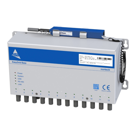
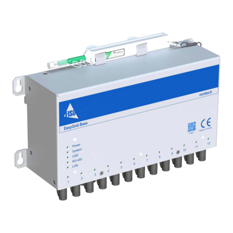
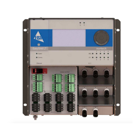
Fiso EasyGrid User manual

EasyGrid User Guide MAN-00084 R 11.0
i
EasyGrid (E-GRID)
User Guide
MAN-00084 R 11.0

EasyGrid User Guide MAN-00084 R 11.0
ii
All rights reserved. No part of this publication may be reproduced, stored in a retrieval system, or
transmitted in any form, be it electronically, mechanically, or by any other means such as photocopying,
recording, or otherwise, without the prior written permission of FISO.
Information provided by FISO is believed to be accurate and reliable. However, no responsibility is
assumed by FISO for its use or for any infringements of patents or other rights of third parties that may
result from its use. No license is granted by implication or otherwise under any patent rights of FISO.
FISO’s Commerce and Government Entities (CAGE) code under the North Atlantic Treaty Organization
(NATO) is L0294.
The information contained in this publication is subject to change without notice.
© 2017 FISO Technologies Inc.
Words that FISO considers trademarks have been identified as such. However, neither the presence nor
absence of such identification affects the legal status of any trademark.
Units of measurement in this document conform to SI standards and practices
FISO Technologies Inc.
500, Ave St-Jean-Baptiste, suite 195
Québec (Québec)
G2E 5R9, Canada
Tel : +1 418 688 8065
Fax : +1 418 688 8067
www.fiso.com

EasyGrid User Guide MAN-00084 R 11.0
iii
1Table of Content
2Product Certification ...................................................................................................................1
2.1 CE Information............................................................................................................................... 1
2.2 Independent Laboratory Testing................................................................................................... 1
3Safety Information......................................................................................................................2
3.1 Safety Conventions........................................................................................................................ 2
3.2 Safety Information......................................................................................................................... 2
3.3 Unpacking and Inspection ............................................................................................................. 3
4First Steps...................................................................................................................................4
4.1 Introducing the Nortech EasyGrid................................................................................................. 4
4.2 Quick Start ..................................................................................................................................... 4
4.2.1 Powering the EasyGrid .......................................................................................................... 4
4.2.2 Connecting Temperature Sensors ......................................................................................... 5
4.2.3 Reading Temperature Measurements .................................................................................. 6
5Hardware Configuration..............................................................................................................7
5.1 Dimensions .................................................................................................................................... 7
5.2 Front Panel Overview .................................................................................................................... 8
5.3 Bottom Panel Overview................................................................................................................. 9
5.4 Maintenance Panel Overview ....................................................................................................... 9
5.5 TFT Display................................................................................................................................... 10
5.6 Action Buttons or State Icons...................................................................................................... 11
5.7 Communication and System Status LED...................................................................................... 11
5.8 USB Configuration Port................................................................................................................ 11
5.9 Power Input................................................................................................................................. 12
5.10 Power Switch............................................................................................................................... 12
5.11 Analog Output ............................................................................................................................. 13
5.12 RS-485/RS-422 Ports ................................................................................................................... 14
5.13 Programmable Alarm/Relay Terminal Block ............................................................................... 16
5.14 System Relay (Fail Safe)............................................................................................................... 17
5.15 Protective Conductor Terminal ................................................................................................... 17

EasyGrid User Guide MAN-00084 R 11.0
iv
5.16 Optical Connector........................................................................................................................ 18
5.17 Ethernet Port (Optional).............................................................................................................. 19
6Firmware Settings ..................................................................................................................... 20
6.1 Channel Settings.......................................................................................................................... 21
6.2 Alarm Settings ............................................................................................................................. 23
6.3 Statistic Settings .......................................................................................................................... 35
6.4 Analog Output Settings ............................................................................................................... 36
6.5 Information Settings.................................................................................................................... 40
6.6 Log Settings ................................................................................................................................. 43
6.7 Display Settings ........................................................................................................................... 48
6.8 Communication Settings ............................................................................................................. 51
7Monitoring Screens................................................................................................................... 54
7.1 Temperature Values & Alarm State ............................................................................................ 55
7.2 Alarm ........................................................................................................................................... 56
7.3 Statistics....................................................................................................................................... 57
7.4 Analog.......................................................................................................................................... 58
7.5 Information.................................................................................................................................. 59
7.6 Diagnostic .................................................................................................................................... 60
8Nortech Client Software ............................................................................................................ 62
8.1 Getting Started ............................................................................................................................ 62
8.1.1 Installing the Program ......................................................................................................... 62
8.2 Main Window .............................................................................................................................. 63
8.3 Connecting to the EasyGrid......................................................................................................... 64
8.4 Firmware Update......................................................................................................................... 65
9Resetting to Factory Defaults .................................................................................................... 66
9.1 Resetting to Factory Defaults ...................................................................................................... 66
10 FISO Contact Information .......................................................................................................... 66
10.1 FISO Service Center ..................................................................................................................... 66

EasyGrid User Guide MAN-00084 R 11.0
1
2Product Certification
2.1 CE Information
Electronic test equipment is subject to the EMC Directive in the European
Union. The EN61326 standard prescribes both emission and immunity
requirements for laboratory, measurement, and control equipment.
This unit has been tested and found to comply with the limits for a Class A
digital device. Contact FISO for access to the Declaration of Conformity.
2.2 Independent Laboratory Testing
This unit has undergone extensive testing according to the European Union Directive and Standards. All
pre-qualification tests were performed internally, at FISO, while final tests were performed externally, at
an independent, accredited laboratory. This guarantees the unerring objectivity and authoritative
compliance of all test results.
Use of shielded remote I/O cables, with properly grounded shields and metal connectors, is
recommended in order to reduce radio frequency interference that may emanate from these cables.
Shielded I/O cables are recommended to improve protection against lightning surge if unit or cables are
installed in an outdoor area. See certificate and tests of compliance.
EasyGrid has been extensively tested to stringent environmental standards to ensure it remains reliable
when used under published specifications.
Contact FISO for any inquiry related to monitor certification.

EasyGrid User Guide MAN-00084 R 11.0
2
3Safety Information
3.1 Safety Conventions
Before using the product described in this manual, you should understand the following conventions:
DANGER
Indicates a potentially hazardous situation that, if not avoided,
could result in death or serious injury. Do not proceed unless
you understand and meet the required conditions.
WARNING
Indicates a potentially hazardous situation that, if not avoided,
may result in minor or moderate injury. Do not proceed unless
you understand and meet the required conditions.
CAUTION
Indicates a potentially hazardous situation that, if not avoided,
may result in component damage. Do not proceed unless you
understand and meet the required conditions.
IMPORTANT
Refers to information about this product you should not
overlook.
3.2 Safety Information
The level of radiation from the monitor light sources is below the level known to cause eye injury
through accidental short-term exposure. However, avoid prolonged exposure to light emitted from the
fiber and do not stare directly at any light beam, visible or not.
The following safety instructions must be observed whenever the EasyGrid is operated. Failure to comply
with any of these instructions or with any precaution or warning contained in the Nortech Fiber Optic
Thermometer and Client Software user’s guide is in direct violation of the standards of design,
manufacture and intended uses of the EasyGrid. FISO assumes no liability for the customer failure to
comply with these safety requirements. THIS PRODUCT IS NOT DESIGNED FOR USE IN LIFE SUPPORT OR
CRITICAL HUMAN APPLICATIONS.
In no case will FISO be liable to the buyer, or to any third parties, for any consequential damage or
indirect damage that is caused by product failure, malfunction, or any other problem.
FISO recommends using the qualified power supply available for purchase with your EasyGrid and verify
that the voltage specifications indicated on the power supply are compatible with the AC voltage and
frequency delivered at the power outlet.

EasyGrid User Guide MAN-00084 R 11.0
3
When using any electrical appliance, basic safety precautions should be followed, including the
following:
Do not operate in wet/damp conditions.
Do not expose to outdoor conditions. Install the unit in a protective enclosure.
Do not operate in an explosive atmosphere.
Keep product surfaces clean and dry.
WARNING
This equipment must be used as specified or the protection provided by the equipment may be
compromised. You must use this product in a normal mode and should not deviate from the
written instructions provided.
CAUTION
There are no user serviceable parts inside the Nortech EasyGrid. Adjusting parts inside the unit
can affect instrument performance. If you adjust parts, you will need to verify the equipment for
good performance. Refer servicing of any other parts to qualified personnel.
3.3 Unpacking and Inspection
The EasyGrid unit is shipped inside a cardboard box designed to give maximum protection during
shipment. If the shipping box external surface is damaged, notify your shipping department immediately.
Your shipping department may want to notify the carrier.
If the shipping box is not damaged, carefully remove and identify all of the components listed below.
Contact FISO or your local representative if any of the components are missing. We recommend you save
the shipping box for future storage or transportation.
The EasyGrid package should include the following components:
Nortech EasyGrid
Power terminal wires (16 AWG)
USB interface cable
ST Optical Connector One Click Cleaner
Calibration Certificate
EasyGrid User Guide
Nortech Client software installation removable storage device

EasyGrid User Guide MAN-00084 R 11.0
4
4First Steps
4.1 Introducing the Nortech EasyGrid
The EasyGrid fiber optic temperature measurement system is designed for real-time monitoring of
transformer hotspots.
It can be configured to have 4 to 18 channels. Modules can be daisy chained to a maximum of 32, which
gives the possibility to have up to 576 channels in a single system. Each unit has multiple serial
interfaces (1 x USB and 1 x RS485) and 1x optional Ethernet communication port. Supported
communication protocols are Nortech and MODBUS (RTU and ASCII). Optional supported
communication protocols are IEC-61850, IEC-60870-5-104, DNP3 and TCPIP-MODBUS, either through an
RJ45 output or an ST optical output.
4.2 Quick Start
4.2.1 Powering the EasyGrid
The EasyGrid requires 24 volts DC (± 10%) power. The power input terminal block is coloured orange for
additional visual aid.
WARNING
Make sure to have a power supply providing the specified power and compatible with your local
power outlet
Power Input
ON/OFF Switch

EasyGrid User Guide MAN-00084 R 11.0
5
1. Make sure that the power switch is OFF when connecting the power supply to the unit.
2. Wire the power input terminal block to a power supply providing the required voltage and
respect connector polarity.
3. Power up the unit using the ON/OFF switch located on the panel above the relay terminal block.
4.2.2 Connecting Temperature Sensors
The EasyGrid is compatible with all FISO TPT-62 sensors. No calibration factor or calibration procedure is
required to get accurate temperature measurements.
1. Remove the protective cap from the Male ST Connector and ST Mating
2. Using the One Click tool clean the Male ST connector and the ST Mating
3. Align the male connector alignment key with the mating slot.
4. Insert ceramic ferrule of the Male ST connector in the ST Mating
5. After making sure it is properly inserted, Push and Twist to lock the spring loaded ring to the ST
Mating

EasyGrid User Guide MAN-00084 R 11.0
6
4.2.3 Reading Temperature Measurements
With the power switch to ON and sensors connected you can read the temperature of each sensor on
the EasyGrid display, up to 18 channels at one time, as displayed below.
For more information on FISO system characteristics, maintenance and installation, refer to document
MAN-00098 Nortech System Installation User Guide.

EasyGrid User Guide MAN-00084 R 11.0
7
5Hardware Configuration
5.1 Dimensions
All EasyGrid monitors ordered with the Fiber Optics Ethernet communication will be of 136mm in depth
for the top portion of the monitor, as shown above. If the EasyGrid is ordered with Standard (No
Ethernet) communication option or the Copper Ethernet option, the depth of the top portion of the
monitor will be of 98mm.
When the Fiber Optic Ethernet communication option is selected, the ST/PC type, TX & RX optical
connectors will be located in the bottom right corner of the front connector panel.

EasyGrid User Guide MAN-00084 R 11.0
8
5.2 Front Panel Overview
Optical Sensor
Connector
Relays
Terminal Block
RS-485/422
Serial Port
Communication
LED
System
Status LED
TFT
Display
Analog
Outputs
System
Relay
Power
Input
Ground
Terminal
Optional
Optical
Ethernet
Connector

EasyGrid User Guide MAN-00084 R 11.0
9
5.3 Bottom Panel Overview
5.4 Maintenance Panel Overview
Power Switch
Optional Copper
Ethernet Port
Dip Switches
Memory Card
Access
USB Port
System Led
Communication Led

EasyGrid User Guide MAN-00084 R 11.0
10
5.5 TFT Display
The EasyGrid offers a large 17.8 cm (7”) color touch screen. From any screen, you can use the bottom
navigation bar to access: Any Temperature Display Screens, the Monitoring Menu or the Settings Menu.
Top and bottom rows of the TFT display:
System Relay
Not Triggered Triggered
Icon and name of the
active screen
Selected temperature unit
YYYY/MM/DD HH:MM:SS = Date and Time
Control Buttons
Back to the previous page
Scroll Up or Down to the
next displayed screen
Enable/Disable Automatic
Scrolling mode
Main Menus Buttons
Go to Temperature Display Screen
Go to Monitoring Menu
Go to Settings Menu
Save Button (In Settings Menus)
Press to save a created or modified parameter
Alarm
Relays
State
Not
Triggered
Triggered

EasyGrid User Guide MAN-00084 R 11.0
11
5.6 Action Buttons or State Icons
To help during navigate through the various Settings and Monitoring displays, one basic interface
information is important to know.
Contoured round knobs, for example , are Action Buttons; they allow parameter modification or
function selection.
Round knobs without contour, for example , are State Icons; they simply provide information on the
state of the related parameter or function.
5.7 Communication and System Status LED
The System Status and the Communication Status LED on the front panel change color depending on the
current unit situation.
Communication Status
The different LED modes and their meanings are:
Color
State
Description
Off
Any
No activity on the communication bus
Amber
Blink
Activity on the communication bus
System Status
The different LED modes and their meanings are:
Color
State
Description
Green
Steady
MODBUS, IEC or DNP3.0 protocol in function
Amber
Steady
Nortech protocol in function
Red
Steady
System Error or at least one sensor is Faulty
Any
Blink
Memory card synchronisation in progress
5.8 USB Configuration Port
The USB configuration interface is accessible in the maintenance panel.
The port serves two purposes:
Communicating with a PC through Nortech Client Software to configure the EasyGrid monitor
parameters, retrieve stored data, upload data or operate the EasyGrid monitor.
Upload updated version of the firmware.

EasyGrid User Guide MAN-00084 R 11.0
12
5.9 Power Input
The EasyGrid accepts only 24 volts DC (± 10%), 40W.
WARNING
To avoid damage to the unit, make sure that the power fed into the input complies with technical
specifications. No other voltage level or range is accepted.
Connect the unit to the power supply using terminal block connectors 24VDC and ground.
Please refer to your power-supply operation manual for important notices and
installation information.
5.10 Power Switch
The power ON/OFF switch is located above the relay terminal blocks
Once all wires are connected, press Ion the switch to power ON the unit. To
power OFF, press the Oon the switch.

EasyGrid User Guide MAN-00084 R 11.0
13
5.11 Analog Output
Each analog output offers a standard 4-20 mA factory configuration.
Analog outputs provide a means of transmitting temperature data directly
from the unit to an external data-gathering system or monitoring
equipment. The EasyGrid provides one output for each temperature channel
present in the unit.
Wire length and gauge are related when connecting analog outputs. For a
run of 100 m or less, recommended gage is 24 AWG or greater. The longer
the run, the smaller the recommended gage will be. Recommendations call
for shielded wire, or for installation in a metal conduit.
Label
Channel
Description
Label
Channel
Description
GND1
1
Analog Output Ground
GND10
10
Analog Output Ground
A1
1
Analog Output
A10
10
Analog Output
GND2
2
Analog Output Ground
GND11
11
Analog Output Ground
A2
2
Analog Output
A11
11
Analog Output
GND3
3
Analog Output Ground
GND12
12
Analog Output Ground
A3
3
Analog Output
A12
12
Analog Output
GND4
4
Analog Output Ground
GND13
13
Analog Output Ground
A4
4
Analog Output
A13
13
Analog Output
GND5
5
Analog Output Ground
GND14
14
Analog Output Ground
A5
5
Analog Output
A14
14
Analog Output
GND6
6
Analog Output Ground
GND15
15
Analog Output Ground
A6
6
Analog Output
A15
15
Analog Output
GND7
7
Analog Output Ground
GND16
16
Analog Output Ground
A7
7
Analog Output
A16
16
Analog Output
GND8
8
Analog Output Ground
GND17
17
Analog Output Ground
A8
8
Analog Output
A17
17
Analog Output
GND9
9
Analog Output Ground
GND18
18
Analog Output Ground
A9
9
Analog Output
A18
18
Analog Output

EasyGrid User Guide MAN-00084 R 11.0
14
5.12 RS-485/RS-422 Ports
A RS-485/RS-422 serial port is provided on the EasyGrid. It can be used to connect the EasyGrid to any
RS485 or RS422 communication bus. It also allows multiple EasyGrid monitors to be link together.
IMPORTANT
When linking many EasyGrid monitors on the same party line, make sure that all units have a different
network ID. The factory-defined address for all units is one (1).
The port is accessible using the dedicated terminal block. The pin layout is the following
A set of dip switches are used to configure the port. They are located behind the access plate on the
right of the screen
Switch
RS-422 Mode
RS-485 Mode
7
Must be Left
Must be Right
6
Must be Left
Must be Right
5
Must be Left
Right: Adds a 120ΩEnd of Line resistor
Left: No end of line resistor
4
Must be Left
Right: Adds a 1kΩpull up resistor
Left: No pull up resistor
3
Must be Left
Right: Adds a 1kΩpull down resistor
Left: No pull down resistor
Label
RS-422
Mode
RS-485
Mode
B+
RX +
Data +
A-
RX -
Data -
B’+
TX +
Do Not Apply
A’-
TX -
Do Not Apply
GND
Ground
Ground

EasyGrid User Guide MAN-00084 R 11.0
15
FISO recommends shielded, twisted pair wiring, 24 AWG with 120Ω line impedance to connect the RS-
485 interface to the network.
FISO also recommends biasing the RS-485 BUS using pull-down and pull-up 1 KΩresistors. Biasing the
RS-485 BUS line will prevent unknown voltage on these lines (RS-485 BUS floating). Leaving the RS-485
BUS floating may result in NORTECH conditioner communication failure.
You must identify the host device on the RS-485 network and then proceed with its 485 BUS line biasing,
as shown above.
Two termination resistors must be installed and have the same characteristic impedance value as the
twisted wire used on the 485 network. RS485 network termination resistors typical values are
respectively 120Ω and ½ Watt.
In Nortech mode, it is possible to connect up to 32 units together. When all units are connected on the
same RS-485 bus, this allows a user to execute the software configuration from a single USB port.
In MODBUS mode, it is possible to connect up to 247 units.

EasyGrid User Guide MAN-00084 R 11.0
16
5.13 Programmable Alarm/Relay Terminal Block
All relay terminal block connectors are form-C relay interfaces.
Relays 1 to 16 are programmable. The programming of the relay is
accomplished either through the EasyGrid display or from a PC
with the Nortech Client software.
Mode
Power Off
Normal
Cond. Met
Exerciser
Normal
NC
COM
NO
NC
COM
NO
NC
COM
NO
NC
COM
NO
Fail Safe
NC
COM
NO
NC
COM
NO
NC
COM
NO
NC
COM
NO
Other manuals for EasyGrid
1
This manual suits for next models
1
Table of contents
Other Fiso Measuring Instrument manuals
