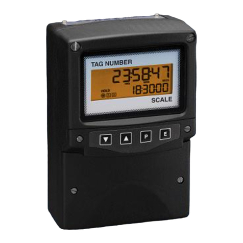
Fiso Nortech EasyTest II User manual

EasyTest II User Guide
EasyTest II
(E-TEST-II)
User Guide
MAN-00119 R1

EasyTest II User Guide
ii

EasyTest II User Guide
iii
All rights reserved. No part of this publication may be reproduced, stored in a retrieval system, or
transmitted in any form, be it electronically, mechanically, or by any other means such as photocopying,
recording, or otherwise, without the express written consent from FISO Technologies Inc. (FISO).
Information provided by FISO is believed to be accurate and reliable. However, no responsibility is
assumed by FISO for its use or for any infringements of patents or other rights of third parties that may
result from its use. No license is granted by implication or otherwise under any patent rights of FISO.
FISO’s Commerce and Government Entities (CAGE) code under the North Atlantic Treaty Organization
(NATO) is L0294.
The information contained in this publication is subject to change without notice.
© 2020 FISO Technologies Inc.
Words that FISO considers trademarks have been identified as such. However, neither the presence nor
absence of such identification affects the legal status of any trademark.
Units of measurement in this document conform to SI standards and practices
Fiso Technologies Inc.
500, Ave St-Jean-Baptiste, suite 195
Québec (Québec)
G2E 5R9, Canada
Tel : +1 418 688 8065
Fax : +1 418 688 8067
www.fiso.com

EasyTest II User Guide
iv
1Table of Content
2Product Certification...................................................................................................................1
CE Information............................................................................................................................... 1
Independent Laboratory Testing................................................................................................... 1
Declaration of conformity ............................................................................................................. 2
3Safety Information......................................................................................................................3
Safety Conventions........................................................................................................................ 3
Safety Information......................................................................................................................... 4
Unpacking and Inspection............................................................................................................. 5
Handling Optical Cable .................................................................................................................. 6
Cleaning Fiber Optic Connectors................................................................................................... 7
4Hardware Configuration............................................................................................................10
Introducing the EasyTest II.......................................................................................................... 10
Overview...................................................................................................................................... 11
Powering the EasyTest II ............................................................................................................. 13
Optical Connector........................................................................................................................ 14
LCD Display.................................................................................................................................. 16
LED Indicators.............................................................................................................................. 16
Informations................................................................................................................................ 16
Language ..................................................................................................................................... 17
USB Communication Port............................................................................................................ 17
Physical dimensions..................................................................................................................... 18
Weight......................................................................................................................................... 18
5Nortech Client Software............................................................................................................ 19
6Troubleshooting........................................................................................................................ 20
Solving Common Problems ......................................................................................................... 20
Diagnostics values ....................................................................................................................... 21
7Spare parts ............................................................................................................................... 22
8Warranty and Service................................................................................................................23
Annexe A LOG Sheet.........................................................................................................................25

1
2Product Certification
CE Information
Electronic test equipment is subject to the EMC Directive in the European
Union. The EN61326 standard prescribes both emission and immunity
requirements for laboratory, measurement, and control equipment.
This unit has been tested and found to comply with the limits for a Class A
digital device. Please refer to the Declaration of Conformity.
Independent Laboratory Testing
This unit has undergone extensive testing according to the European Union Directive and Standards.
Tests were performed externally, at an independent, accredited laboratory. This guarantees the unerring
objectivity and authoritative compliance of all test results.

2
Declaration of conformity
FISO Technologies Inc., located at 500, Saint-Jean-Baptiste Ave., Suite 195, Quebec, QC, Canada G2E 5R9
Product description: Fiber optic thermometer
Model number(s): EasyTest II
Product category: Electrical equipment for measurement, control and laboratory use.
Complies with the essential requirements of the following applicable European Directive:
2014/30/EU Electromagnetic Compatibility (EMC) Directive,
2011/65/EU Restriction of the use of certain Hazardous Substances (RoHS) Directive
Conformity is assessed in accordance to the following standards:
EMC Standards:
EN61326-1 : (2013)
Emissions/Immunity requirements for laboratory Equipment
CISPR 11: (2015) A1(2016)
Conducted Emissions
Group 1, class A
CISPR 11: (2015) A1(2016)
Radiated emission
Group 1, class A
IEC 61000-4-2 : (2008)
Electrostatic discharge immunity
Contact: ±4kV Air: ±2kV, ±4kV, ±8kV
IEC 61000-4-3 : (2006)
A1(2007) A2(2010)
Radiated electromagnetic field immunity
80-1000MHz: 3V/m
1.4-2GHz: 3V/m
2-2.7GHz: 1V/m
IEC 61000-4-4 : (2012)
Electrical fast transient immunity
Power: ±1kV / 5kHz I/O Ports: N/A
Communication Ports: N/A
IEC 61000-4-5 : (2014)
Surge immunity
Power: ±1kV L-PE / ±0.5kV L-L I/O Ports:
N/A Communication Ports: N/A
IEC 61000-4-6 : (2013)
Immunity to Conducted Disturbances,
Induced by Radio-Frequency Fields
Power: 3V I/O Ports: N/A Communication
Ports: N/A
IEC 61000-4-8 : (2009)
Power Frequency Magnetic Field Immunity
Continuous Field: 3A/m / 50Hz & 60Hz
IEC61000-4-11 : (2004)
Voltage Dips, Short Interruptions and Voltage
Variation Immunity on AC Input
Voltage dips: 0%Un during half cycle 0%Un
during 1 cycle 70%Un during 25 cycles (at
50Hz) 70%Un during 30 cycles (at 60Hz)
Short interruptions: 0%Un during 250
cycles(at 50Hz) 0%Un during 300 cycles (at
60Hz)
Environmental Affairs:
EN50581 : 2012
Articles manufactured on or after the Date of Issue of this declaration of Conformity do not
contain any of the restricted substances in concentration/applications not permitted by the
RoHS Directive
Supplementary information:
Conducted Emissions FCC part 15 (2018) subpart B
Class A 150kHz-30MHz
Radiated Emissions FCC part 15 (2018) subpart B
Class A 30MHz-2GHz
Conducted Emissions ICES-003 (2016)
Class A 150kHz-30MHz
Radiated Emissions ICES-003 (2016)
Class A 30MHz-2GHz

3
3Safety Information
Safety Conventions
Before using the product described in this guide, you should understand the following conventions:
DANGER
Indicates a potentially hazardous situation which, if not avoided,
could result in death or serious injury. Do not proceed unless
you understand and meet the required conditions.
WARNING
Indicates a potentially hazardous situation which, if not avoided,
may result in minor or moderate injury. Do not proceed unless
you understand and meet the required conditions.
CAUTION
Indicates a potentially hazardous situation which, if not avoided,
may result in component damage. Do not proceed unless you
understand and meet the required conditions.
IMPORTANT
Refers to information about this product you should not
overlook.

4
Safety Information
The level of radiation is below the level known to cause eye injury through accidental short-term
exposure. However, avoid prolonged exposure to light emitted from the fiber and do not stare directly
at a light beam, visible or not.
The following safety instructions must be observed whenever the EasyTest II is operated. Failure to
comply with any of these instructions or with any precaution or warning contained in the Fiber Optic
Thermometer user’s guide is in direct violation of the standards of design, manufacture and intended
uses of the EasyTest II. FISO assumes no liability for the customer failure to comply with these safety
requirements.
THIS PRODUCT IS NOT DESIGNED FOR USE IN LIFE SUPPORT OR CRITICAL APPLICATIONS.
In no case will FISO be liable to the buyer, or to any third parties, for any consequential damage or
indirect damage which is caused by product failure, malfunction, or any other problem.
When using any electrical appliance, basic safety precautions should be followed, including the
following:
You should only use the power supply that came with your EasyTest II and verify that the voltage
specifications indicated on the power supply are compatible with the AC voltage and frequency delivered
at the power outlet.
Do not operate in wet/damp conditions.
Do not expose to outdoor conditions.
Do not operate in an explosive atmosphere.
Keep product surfaces clean and dry.
Avoid excessive physical shock or vibration
Do not expose to temperature higher than 60 degC
WARNING
This equipment must be used as specified or the protection provided by the equipment may
be compromised. You must use this product in a normal mode and should not deviate from
the written instructions provided.

5
Unpacking and Inspection
The EasyTest II Tester is shipped inside a carton designed to give maximum protection during shipment.
CAUTION
If the outside of the shipping carton is damaged, notify your shipping department immediately.
Your shipping department may want to notify the carrier.
Carefully remove the carring case from the carton and open-it, identify all of the components listed
below.
Contact FISO or your local representative if any of the components are missing.
We recommend you save the shipping carton for future storage or transportation.
The EasyTest II toolbox includes the following components:
1X EasyTest II unit
1X EasyClean, Optical Connector Cleaner (attached to the EasyTest II unit)
1X CFO-ET, a short optical extension / optical port saver (attached to the EasyTest II unit)
1X USB interface cable
1X Power Adapter
1X EasyCheck, a small validation probe
1X ST-ST mating
1X Calibration Certificate
1X Carrying case

6
Handling Optical Cable
CAUTION
The core of any fiber optic cable is glass. For this reason it should be handled with care and
should not be viewed like a standard conventional electrical cable. If it is pinched, twisted,
over bent or crushed, the glass core will break and the light attenuation will occur at this point.
Fiber optic sensors are pretty robust but…
Avoid sharp bend
Avoid kinking, twisting
Avoid putting any tension on the cable
Avoid dropping connector on hard surfaces
Like your car Windshield or your glasses, the optical connector must stay clean to gives good results.
Always keep the protective cap on, to protect them when they are not connected
Clean both connectors each time you connect them, because a small particle of dust on one connector
could scratch both connectors.
Here are typical inspection picture of optical connector made with a Fiber inspection probe
Before Cleaning
First click cleaning
Second Click cleaning

7
Cleaning Fiber Optic Connectors
The unit comes with an EasyClean tool. This high-performance device is designed to ease connector
ferule end faces cleaning. Read carefully the below instruction before using the device.
Important
The EasyClean is designed to clean the fiber optic connectors.
FISO is not liable for any damage caused in attempts to apply this device to other applications.
Always keep the protection cap on when not in use to avoid contamination.
3.5.1 EasyClean Tool General Operation
The EasyClean cleaner is easy to use, but you need to be careful not to do the following:
Do not use this tool to clean oily connector, as this will cause contamination of the cleaning
cloth.
Do not touch the cleaning cloth as this will cause contamination.
Do not use this cleaner when the cloth is empty. This may cause damage to the connector.
Do not pull the cleaning cloth, use only the device body.
Do not attempt to dissemble as this can cause damage to the device and void the warranty.
Do not try to re-use the cleaning cloth as this will eliminate the cleaner’s effectiveness and void
the warranty.
The amount of cloth left in the tool is shown in the window located in the body.

8
3.5.2 Cleaning the Male ST Connector
Step 1: Open the end-cover on the Guide Cap
Step 2: Insert the Connector Ferule into the Guide Cap
Step 3: Push the Cleaner body against the connector ferrule, the black neck of the cleaner will enter
into the blue body of the cleaner and you will ear a Click this will wipe the cleaning cloth against the
connector face and clean it.
Step 4: Turn the Cleaner body by 90°
Step 5: Push the Cleaner body against the ferrule connector for a second time

9
3.5.3 Cleaning the ST Mating
Step 1:Remove the Guide Cap from the Device
Step 2: Insert the cleaner tip in the mating, and Push the outer shell to clean the connector face
Step 3: Turn the cleaner body by 90°
Step 4: Push the outer shell a second time to clean the connector face

10
4Hardware Configuration
Introducing the EasyTest II
The EasyTest-II, is a single channel battery operated portable temperature Tester for TPT-62 GaAs Fiber
optic Hot spot temperature sensors.
It came in a ‘’Toolbox’’ with all the tools to assist you at each step of the transformer assembly to
validate the installation of Fiber optic temperature sensors or to perform on site testing.
Please have a look at the EasyTest II video, it show how to use-it.
You will find others informative videos on our web site : https://fiso.com/en/support/?ca=videos

11
Overview
Menu Navigation
Keypad
2D Bar Code –
Linking to Web
Support page
LCD Display
Units LEDs
USB port
Main optical
Connector
EasyClean
TOP
Port saver optical
Connector
Shock Bumpers

12
Internal Battery
capacity indicator
Charger Power
Input
ON and OFF
Switch
Left Side
Right Side
Main Optical
Connector
Port saver optical
Connector
Rear
CFO-ET :
Port Saver /
Short Extension
Model and
Serial number
Hook for the
CFO-ET

13
Powering the EasyTest II
4.3.1 Power supply
The external power supply of EasyTest II has the following output characteristics:
Barrel connector; 5.5mm OD X 2.1mm ID X 9.5mm long, positive center
24VDC / 60W,
4.3.2 Battery
The EasyTest II has a built-in 49Wh rechargeable Lithium Ion battery.
With its internal battery, the system can operate on its own for as long as 16 hours of continuous
operations.
The battery capacity indicator on the left side tells you the remaining capacity in the battery.
Each LCD segment represent 20% of the full charge capacity.
A complete charge with the unit Off will take about 3h at a room temperature of 23degC.
You can also recharge the unit while using it, but it could take more time.
Note: During the charge, the most significant segment will blink.
Recharge Temperature limits: 0degC to 40degC <= 80%RH
Operating Temperature limits: 0degC to 50degC <= 80%RH
Storage Temperature limits: -20degC to 60degC <= 80%RH
Extended exposure to temperatures above 45degC could degrade battery performance and life.
Battery Life expectancy:
Given normal storage & usage, user can expect the battery to deliver at least 8 hours capacity after 300
charge/discharge cycles at 25degC.
WARNING
To avoid damaging to the unit, make sure to use ONLY the provided power supply.
Using different power inputs may damage the unit. No other voltage level or range is
accepted.

14
Optical Connector
The mechanical life of the optical connector is about 500 mating cycles in a relatively clean environment.
To keep your EasyTest II in good operating condition, we have installed a short optical extension that act
as an optical Port Saver, the CFO-ET.
To protect your EasyTest II optical connector, always keep the CFO-ET connected to the main optical port
of your EasyTest II ‘’A’’ and connect the sensors to the Port Saver optical connector ‘’B’’.
You could also use it as an optical extension to test directly at the tank wall feedthrough.
When the optical connector of the CFO-ET worn out, simply order a new one by contacting
Main Optical
Connector ‘’A’’
Port saver optical
Connector ‘’B’’

15
CAUTION
Use care in handling fiber optic connectors.
Always clean the fiber tip prior to insertion into the connector for optimum performance.
For details on connector cleaning, please refer to 3.5 Cleaning Fiber Optic Connectors
To connect a ST connector, follow these 5 steps:
1. Remove the protective cap from the Male ST Connector and ST Mating.
2. Use the EasyClean tool to clean the Male ST connector and the ST Mating.
3. Align the male connector key with the mating slot.
4. Insert the connector in the mating.
5. Twist to lock.
Key
Slot
Male ST
Connect
ST Mating

16
LCD Display
The LCD display allows visualization of the key information
directly on the unit.
The main display is showing the real-time temperature and the
diagnostic values.
LED Indicators
Temperature Units LEDs
The Temperature LED indicates which units the EasyTest II is
displaying temperature, either °C or °F.
To change the unit,
press the center button to enter the menu,
press 3 times the down arrow to navigate to the setting
press the center button to enter the setting
press the right arrow to change the units
make an off-on
Informations
System Info
Description
Model : Device model
Serial : Device serial number (UID)
Version : Device current firmware version
To visualize the Information:
press the center button to enter the menu,
press 4 times the down arrow to navigate to Information
press the center button to enter the Information
make an off-on
This manual suits for next models
2
Table of contents
Other Fiso Measuring Instrument manuals
